
一、 緒論 / I. Introduction
在現代複循環發電廠(Combined Cycle Power Plant, CCPP)長期處於高壓與高溫的營運環境中,管線系統的完整性與可靠度無疑是維持電廠連續運轉的核心基石。針對公稱管徑小於或等於2英吋(NPS ≦ 2)的小管徑管線(Small Bore Piping),工業界傳統上廣泛採用1.0D短半徑套銲彎頭(Socket Weld Elbow)以達成管線之連接與空間轉向。依據 ASME B31.1(動力管線)第127.3(e)段及 ASME B31.3(製程管線)第328.5.2段之規範要求,套銲接頭在施銲前必須強制預留約1.6毫米(1/16英吋)的間隙,旨在吸收銲接高溫及冷卻階段之熱膨脹應力,進而防止銲道根部產生龜裂1。In the long-term high-pressure and high-temperature operating environment of modern Combined Cycle Power Plants (CCPP), the integrity and reliability of the piping system are undoubtedly the core cornerstones for maintaining continuous plant operations. For small bore piping with a nominal pipe size of 2 inches or less (NPS ≦ 2), the industry has traditionally widely adopted 1.0D short-radius socket weld elbows to achieve piping connections and spatial directional changes. According to the mandatory requirements of ASME B31.1 (Power Piping) paragraph 127.3(e) and ASME B31.3 (Process Piping) paragraph 328.5.2, a gap of approximately 1.6 mm (1/16 inch) must be reserved before welding the socket joint. This is designed to absorb the thermal expansion stress during the high-temperature welding and subsequent cooling phases, thereby preventing cracks at the weld root1.
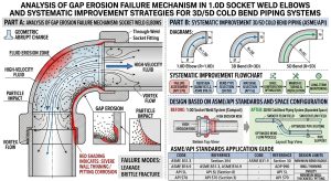
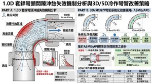
然而,此一基於應力釋放而設計的保護性間隙,在實際的流體動態運作中,卻逐漸演變為導致管線退化與破損的致命弱點。該幾何間隙在管壁內部形成一道微型環狀凹槽,澈底破壞了內壁的平滑連續性,進而引發邊界層流場剝離、紊流加劇與局部渦流(Vortex Shedding)5。在CCPP廠高流速且常伴隨氣液兩相流(Gas-Liquid Two-Phase Flow)或含沙微粒的多相流環境中,此一流場突變會引發極其嚴重的沖蝕-腐蝕(Erosion-Corrosion)現象。防護性氧化膜在此反覆的機械與化學作用下遭到破壞,最終造成彎頭下游直管處之管壁急劇減薄與穿孔洩漏5。此外,套銲接頭先天具有極高的應力強化係數(Stress Intensification Factor, SIF),在長期熱循環與震動負載的疊加下,亦極易誘發高週疲勞或熱疲勞破壞3。However, this protective gap, designed for stress relief, gradually evolves into a fatal weakness leading to piping degradation and failure in actual fluid dynamic operations. This geometric gap forms a micro-annular groove inside the pipe wall, completely destroying the smooth continuity of the inner wall, which in turn triggers boundary layer flow separation, intensified turbulence, and localized vortex shedding5. In the high-velocity environment of CCPP plants, often accompanied by gas-liquid two-phase flow or multiphase flow containing sand particles, this sudden flow field change induces extremely severe erosion-corrosion phenomena. The protective oxide film is destroyed under repeated mechanical and chemical actions, ultimately causing rapid wall thinning and perforation leakage in the downstream straight pipe of the elbow5. Furthermore, socket weld joints inherently possess a very high Stress Intensification Factor (SIF). Under the superimposition of long-term thermal cycling and vibration loads, they are highly prone to high-cycle fatigue or thermal fatigue failures3.
為澈底根除套銲間隙所衍生的流場突變與應力集中問題,將傳統1.0D套銲彎頭替換為一體成型的大曲率冷作彎管,已成為國際先進電廠在資產完整性維護上的系統化改善趨勢。本報告旨在深度剖析1.0D套銲彎頭間隙之流場沖蝕與微環境退化機制,並結合美國石油學會(API 571、API 570)的損傷機制與檢測評估標準進行系統性論證。同時,本研究從固體力學與冶金學角度,深入探討5D及3D冷作彎管在 ASME B31.1 與 B31.3 最新規範下之受壓壁厚計算、應變極限與彎後熱處理(PBHT)要求。透過多維度的科學分析與工程實務探討,本報告將為CCPP廠降低強迫停機率(Forced Outage Rate, FOR)及延長平均故障間隔時間(MTBF)提供具備法規基礎之具體戰略方針。To thoroughly eradicate the flow field mutations and stress concentration problems derived from socket weld gaps, replacing traditional 1.0D socket weld elbows with integral large-curvature cold bending pipes has become a systematic improvement trend for asset integrity maintenance in advanced international power plants. This report aims to deeply analyze the flow field erosion and micro-environment degradation mechanisms of 1.0D socket weld elbow gaps, systematically demonstrating this with the damage mechanisms and inspection evaluation standards of the American Petroleum Institute (API 571, API 570). Concurrently, from the perspectives of solid mechanics and metallurgy, this study delves into the pressure wall thickness calculations, strain limits, and Post-Bend Heat Treatment (PBHT) requirements of 5D and 3D cold bending pipes under the latest ASME B31.1 and B31.3 codes. Through multi-dimensional scientific analysis and engineering practice exploration, this report provides specific, code-based strategic guidelines for CCPP plants to reduce the Forced Outage Rate (FOR) and extend the Mean Time Between Failures (MTBF).
二、 1.0D套銲彎頭之間隙幾何特徵與流體力學效應 / II. Geometric Characteristics and Fluid Dynamics Effects of Gaps in 1.0D Socket Weld Elbows
2.1 ASME規範之間隙預留要求及其物理悖論 / 2.1 ASME Code Gap Reservation Requirements and Their Physical Paradox
在小管徑管線的施工實務中,套銲因其裝配簡便、無需精確對心且無須執行管端倒角加工等顯著優勢,被廣泛應用於高壓蒸汽、冷凝水與化學注藥等系統。依據 ASME B31.1 及 ASME B31.3 的強制性構造規定,管子插入套銲管件底部後,必須向外回撤大約1.6毫米之間隙,隨後方可於外部進行填角銲(Fillet Weld)2。In the construction practice of small bore piping, socket welding is widely applied in high-pressure steam, condensate, and chemical injection systems due to its significant advantages of easy assembly, no need for precise alignment, and no requirement for pipe-end beveling. According to the mandatory construction provisions of ASME B31.1 and ASME B31.3, after the pipe is inserted into the bottom of the socket weld fitting, it must be withdrawn to reserve a gap of approximately 1.6 mm before a fillet weld can be executed externally2.
此一法規的制定初衷在於釋放熱應力(Stress Relief)。由於在銲接過程的高溫熱輸入與隨後的冷卻收縮階段,母材與銲道金屬間將產生極大的軸向熱膨脹不匹配1;因此,若管子直接觸底而無任何預留間隙(Bottoming out),這種被機械結構強制鎖死(Locked-in)的殘餘應力,在受到營運初期的高溫熱循環作用時,極易從銲道根部的微裂紋迅速演變為致命的疲勞裂縫1。由此可見,該間隙在冶金與銲接應力控制上具有絕對的必要性。然而,正是這個滿足固體力學需求的幾何構造,卻在流體動力學上形成了一個無法忽視的微型缺陷,成為管線內部最脆弱的侵蝕起源點。The original intent of this code requirement is stress relief. Because of the high-temperature heat input during the welding process and the subsequent cooling shrinkage phase, a significant axial thermal expansion mismatch will occur between the base metal and the weld metal1. Therefore, if the pipe bottoms out without any reserved gap, this locked-in residual stress caused by the mechanical structure can easily evolve rapidly from micro-cracks at the weld root into fatal fatigue cracks when subjected to high-temperature thermal cycling during the initial operational stage1. Thus, it is evident that this gap is absolutely necessary for metallurgical and welding stress control. However, it is precisely this geometric structure, which satisfies solid mechanics requirements, that forms a non-negligible micro-defect in fluid dynamics, becoming the most vulnerable erosion origin inside the piping.
2.2 間隙引發之流場突變與兩相流沖蝕效應 / 2.2 Flow Field Mutations and Two-Phase Flow Erosion Effects Triggered by the Gap
當高壓流體流經平滑的直管進入套銲彎頭時,原本緊貼管壁的穩定邊界層(Boundary Layer)在經過這1.6毫米的環狀凹槽時,會遭遇幾何截面積的猝然改變5。根據計算流體力學(CFD)的模擬研究顯示,此種幾何不連續性會造成流體動量(Momentum)在近壁面的瞬間損失,進而引發嚴重的流場剝離(Flow Separation)現象7。剝離的流體在間隙內部形成流動滯留區與強烈的局部渦流(Vortex)。這些渦流不僅消耗流體能量造成壓力降,更會將流體中的微粒與腐蝕性離子捲入並困於其中4。此外,若現場銲接過程中產生銲道根部凸出物(Root Protrusion),將進一步阻礙流場,宛如微型節流閥般加劇局部的紊流強度13。When high-pressure fluid flows through a smooth straight pipe into a socket weld elbow, the stable boundary layer originally clinging to the pipe wall encounters a sudden change in geometric cross-sectional area as it passes through this 1.6 mm annular groove5. According to Computational Fluid Dynamics (CFD) simulation studies, this geometric discontinuity causes an instantaneous loss of fluid momentum near the wall, triggering a severe flow separation phenomenon7. The separated fluid forms a stagnation zone and intense local vortices within the gap. These vortices not only consume fluid energy causing pressure drops but also entrain and trap micro-particles and corrosive ions from the fluid4. Additionally, if root protrusions are generated during on-site welding, they further obstruct the flow field, intensifying local turbulence like a miniature throttle valve13.
在氣液兩相流環境中,此紊流效應尤為顯著且極具破壞性。以高壓氣體或液化石油氣(LPG)管線為例,流場數值模擬證實,高速氣流帶動下的微小液滴會因極大的慣性力而無法順利隨氣流轉向,進而以極高的動能與銳角撞擊彎頭出口及其下游直管內壁6。研究指出,這類衝擊會直接導致第一道接觸流體的母管壁面被完全侵蝕。值得注意的是,流場動態特徵也深受粒子粒徑與管線曲率的影響。在串聯式彎頭系統中,受離心力與二次流(Secondary flow)的作用,小顆粒微粒展現出較強的流場跟隨性,能更充分地與管壁發生高頻碰撞,導致外弧側45度至55度區域呈現最高速率的局部沖蝕14。這也合理解釋了為何許多電廠的失效穿孔位置,並非均勻發生在彎頭本體,而是高度集中在緊鄰彎頭出口下游的直管與銲道交界處5。In a gas-liquid two-phase flow environment, this turbulence effect is particularly prominent and highly destructive. Taking high-pressure gas or Liquefied Petroleum Gas (LPG) pipelines as an example, flow field numerical simulations confirm that tiny droplets driven by high-speed airflow cannot smoothly turn with the gas stream due to massive inertial forces, subsequently impacting the elbow outlet and its downstream straight pipe inner wall with extremely high kinetic energy and acute angles6. Research indicates that such impacts directly lead to the complete erosion of the base pipe wall that first contacts the fluid. Notably, flow dynamic characteristics are also profoundly influenced by particle size and pipe curvature. In tandem elbow systems, due to centrifugal force and secondary flow, smaller particles exhibit stronger flow-following capabilities and can more fully engage in high-frequency collisions with the wall, resulting in the highest rate of localized erosion in the 45 to 55-degree region of the extrados (outer arc)14. This also rationally explains why the failure perforation locations in many power plants do not occur uniformly in the elbow body itself but are highly concentrated at the boundary between the downstream straight pipe and the weld, immediately adjacent to the elbow outlet5.
三、 基於API 571之退化與破損機制深層分析 / III. In-Depth Analysis of Degradation and Failure Mechanisms Based on API 571
美國石油學會出版的 API 571(Damage Mechanisms Affecting Fixed Equipment in the Refining Industry)是評估工業高壓管線設備損傷機制之權威指南16。針對CCPP廠套銲彎頭及其周邊管線,間隙的存在誘發了多種損傷機制的協同交互作用(Synergistic Effect),其中以沖蝕-腐蝕、縫隙腐蝕、疲勞破壞與高溫潛變最具威脅。API 571 (Damage Mechanisms Affecting Fixed Equipment in the Refining Industry), published by the American Petroleum Institute, is an authoritative guide for evaluating damage mechanisms in industrial high-pressure piping equipment16. Regarding the socket weld elbows and surrounding piping in CCPP plants, the presence of the gap induces a synergistic effect of multiple damage mechanisms, among which erosion-corrosion, crevice corrosion, fatigue failure, and high-temperature creep are the most threatening.
3.1 沖蝕-腐蝕(Erosion-Corrosion)與微粒撞擊 / 3.1 Erosion-Corrosion and Particle Impingement
沖蝕-腐蝕是一種結合機械性材料磨耗與電化學溶解的複合型金屬流失機制5。在CCPP的管線內部,碳鋼表面在適當的溫度(大於60°C)、pH值與無氧水質條件下,通常會形成一層緻密的防護性氧化膜,如磁鐵礦(Fe3O4)或碳酸亞鐵( FeCO3),以抑制基材進一步氧化5。然而,高流速環境會降低金屬表面的過飽和度,進而抑制防護膜的沉澱速率;同時,套銲間隙所引發的高強度紊流與固態微粒撞擊,產生了超過防護膜降伏應力的機械剪應力,強行將防護膜剝離5。Erosion-corrosion is a composite metal loss mechanism combining mechanical material wear and electrochemical dissolution5. Inside CCPP piping, the carbon steel surface typically forms a dense protective oxide film, such as magnetite (Fe3O4) or iron carbonate (FeCO3), under appropriate temperature (greater than 60°C), pH, and anaerobic water conditions, to inhibit further oxidation of the substrate5. However, a high flow velocity environment reduces the supersaturation on the metal surface, thereby inhibiting the precipitation rate of the protective film. Simultaneously, the high-intensity turbulence and solid particle impingement triggered by the socket weld gap generate mechanical shear stress exceeding the yield stress of the protective film, forcibly stripping it away5.
一旦底層的活性金屬暴露於腐蝕介質中,陽極溶解反應便會迅速發生,並試圖重新生成氧化膜;隨後,高速流體再次將新生成的膜沖刷剝落21。此一「成膜-剝離-再成膜」的惡性循環,導致材料流失率較單純的無流動水溶液腐蝕高出2至4倍之多。若環境壓力降至飽和蒸氣壓以下,還可能引發空蝕現象(Cavitation Erosion),氣泡在管壁附近劇烈崩塌所產生的微噴流對材料表面的打擊,將使沖蝕-腐蝕速率呈現指數型惡化11。Once the underlying active metal is exposed to the corrosive medium, anodic dissolution reactions occur rapidly, attempting to regenerate the oxide film; subsequently, the high-speed fluid washes away the newly formed film again21. This vicious cycle of “film formation – stripping – re-formation” leads to a material loss rate 2 to 4 times higher than that of simple non-flowing aqueous corrosion. If the environmental pressure drops below the saturated vapor pressure, cavitation erosion may also occur. The impact of micro-jets produced by the violent collapse of bubbles near the pipe wall on the material surface will cause the erosion-corrosion rate to deteriorate exponentially11.
3.2 縫隙腐蝕(Crevice Corrosion)與極端微環境劣化 / 3.2 Crevice Corrosion and Extreme Micro-Environment Degradation
套銲接頭內這1.6毫米的間隙在本質上構建了一個完美的縫隙幾何構造,成為微環境劣化的溫床。在含有微量氯離子的系統中,縫隙內部的流體極端緩慢甚至停滯,導致溶解氧迅速被陰極還原反應消耗殆盡,形成局部缺氧環境。為維持系統的電中性,外部流體中的氯離子(Cl–)等陰離子會大量向縫隙內遷移,進而產生高度濃縮現象4。This 1.6 mm gap within the socket weld joint essentially constructs a perfect crevice geometry, becoming a breeding ground for micro-environment degradation. In systems containing trace amounts of chloride ions, the fluid inside the crevice flows extremely slowly or even stagnates, causing dissolved oxygen to be rapidly depleted by cathodic reduction reactions, forming a localized anoxic environment. To maintain system electroneutrality, anions such as chloride ions (Cl–) in the external fluid migrate en masse into the crevice, resulting in a highly concentrated phenomenon4.
金屬在縫隙內發生水解反應會釋放大量氫離子,導致間隙內的pH值急遽下降。例如在特定管線失效分析中發現,當流體中氯離子濃度高達1290 ppm時,縫隙內的微環境pH值竟驟降至2.67至2.91的強酸級別9。此種高氯、低pH值的極端微環境會徹底摧毀鈍化膜,引發嚴重的局部坑蝕(Pitting Corrosion)與金屬快速溶解。此類縫隙腐蝕由內部深處向外侵蝕,外部的常規非破壞檢測(NDE)往往難以在壁厚完全穿透前及早察覺,因此具有極高的隱蔽性與危險性4。Metal hydrolysis reactions inside the crevice release large amounts of hydrogen ions, causing the pH value within the gap to drop sharply. For example, in specific pipeline failure analyses, it was found that when the chloride ion concentration in the fluid reached 1290 ppm, the micro-environment pH inside the crevice plummeted to a strongly acidic level of 2.67 to 2.919. This extreme micro-environment of high chloride and low pH completely destroys the passivation film, triggering severe localized pitting corrosion and rapid metal dissolution. This type of crevice corrosion erodes outward from deep within, and conventional external Non-Destructive Examination (NDE) often struggles to detect it early before the wall thickness is completely penetrated, hence possessing extremely high concealment and danger4.
3.3 應力強化係數(SIF)與多重疲勞破壞機制 / 3.3 Stress Intensification Factor (SIF) and Multiple Fatigue Failure Mechanisms
除了流體沖刷與化學腐蝕的威脅,套銲接頭在機械力學上也處於極端不利之地位。依據最大主應力理論(Maximum Principal Stress Theory),當管線組件中任何一個主應力超過材料的降伏強度時即發生塑性變形,而在長期交變載荷下則會引發疲勞22。根據 ASME B31.1 與 B31.3 的應力分析規範,未經特殊加工的套銲填角銲趾(Weld Toe)具有高達2.1的應力強化係數(SIF = 2.1)3。這意味著,當管線承受由熱膨脹、熱衝擊或設備運轉引起的交變彎矩時,銲趾處的局部應力為名義應力(Nominal Stress)的2.1倍3。Beyond the threats of fluid scouring and chemical corrosion, socket weld joints are also in an extremely disadvantaged position in terms of mechanical mechanics. According to the Maximum Principal Stress Theory, plastic deformation occurs when any principal stress in a piping component exceeds the material’s yield strength, and fatigue will be induced under long-term alternating loads22. Based on the stress analysis codes of ASME B31.1 and B31.3, an untreated socket fillet weld toe has a Stress Intensification Factor (SIF) as high as 2.13. This means that when the piping is subjected to alternating bending moments caused by thermal expansion, thermal shocks, or equipment operation, the local stress at the weld toe is 2.1 times the nominal stress3.
在CCPP廠頻繁的啟停機(Start-up and Shut-down transients)過程中,管線經歷劇烈的溫度變化,產生巨大的軸向與徑向熱應力11。極高的SIF使得套銲接頭處極易萌生熱疲勞微裂紋。針對小管徑套銲接頭的高週彎曲疲勞與震動疲勞實驗顯示,在較高應力水準下,疲勞裂紋傾向於從銲趾處萌生;而在較低應力水準或存在內部缺陷時,裂紋則容易從未熔合的銲根(Root)處萌生10。儘管業界有時會藉由研磨銲趾將SIF降至1.3,或採用特殊銲材試圖改善表面應力分佈3,但這些技術僅能緩解外部的應力集中,對於內部間隙所造成的根部應力集中與縫隙腐蝕依然毫無助益3。During the frequent start-up and shut-down transients of CCPP plants, the piping undergoes drastic temperature changes, generating enormous axial and radial thermal stresses11. The extremely high SIF makes the socket weld joint highly susceptible to initiating thermal fatigue micro-cracks. High-cycle bending fatigue and vibration fatigue experiments on small bore socket weld joints show that at higher stress levels, fatigue cracks tend to initiate from the weld toe; whereas at lower stress levels or in the presence of internal defects, cracks are prone to initiate from the unfused weld root10. Although the industry sometimes grinds the weld toe to reduce the SIF to 1.3, or uses special welding materials to try and improve surface stress distribution3, these technologies can only alleviate external stress concentration, providing absolutely no help against the root stress concentration and crevice corrosion caused by the internal gap3.
| 機制/特徵 Mechanism/Feature | 1.0D套銲彎頭 1.0D Socket Weld Elbow | 3D/5D冷作彎管 3D/5D Cold Bending Pipe | 物理/力學影響評估 Physical/Mechanical Impact Assessment |
| 幾何間隙 Geometric Gap | 存在 1.6 mm 規範間隙 (1.6 mm code gap exists) | 無間隙,連續平滑 (No gap, smooth continuity) | 間隙導致渦流、剝離與縫隙腐蝕,3D/5D完全消除此風險 (Gap causes vortices, separation & crevice corrosion; 3D/5D eliminates this risk) |
| 應力強化係數 SIF | 2.1 (未研磨 Un-ground) / 1.3 (研磨 Ground) | 1.0 (等同直管或平滑彎管 Equivalent to straight pipe) | 套銲的高SIF是疲勞根源,3D/5D大幅提升疲勞壽命 (High SIF of socket welds is the root of fatigue; 3D/5D greatly improves fatigue life) |
| 流場特性 Flow Characteristics | 劇烈紊流、液滴二次撞擊 (Severe turbulence, secondary droplet impacts) | 層流維持佳、擾動極小 (Good laminar maintenance, minimal disturbance) | 大曲率半徑引導平順轉向,極大化降低動能沖擊 (Large radius guides smooth turns, maximizing kinetic impact reduction) |
| 殘餘應力來源 Residual Stress Source | 銲接熱影響區(HAZ)與底觸應力 (Weld HAZ and bottoming stress) | 均勻冷作變形,可經PBHT消除 (Uniform cold forming, can be eliminated via PBHT) | 套銲局部殘餘拉應力大,冷彎管經熱處理後材質均勻 (Socket welds have high local tensile residual stress; heat-treated cold bends have uniform material) |
四、 基於API 570之管線檢測策略與風險基礎完整性管理 / IV. Piping Inspection Strategies and Risk-Based Integrity Management Based on API 570
為防範上述多重損傷機制引發的無預警失效,實施嚴謹的在役管線檢測與完整性管理勢在必行。API 570(Piping Inspection Code)提供了標準化的檢測與評估技術指導26。然而,針對極易發生間隙沖蝕與疲勞破裂的小管徑套銲系統,API 570 雖提出了實務檢測策略,但也同時暴露出傳統檢測在被動防禦上的侷限性。To prevent unpredicted failures triggered by the aforementioned multiple damage mechanisms, implementing rigorous in-service piping inspection and integrity management is imperative. API 570 (Piping Inspection Code) provides standardized technical guidance for inspection and evaluation26. However, concerning small bore socket weld systems highly susceptible to gap erosion and fatigue rupture, although API 570 proposes practical inspection strategies, it concurrently exposes the limitations of traditional inspection as a passive defense.
4.1 狀態監測點(CML)之選定與優化佈局 / 4.1 Selection and Optimized Layout of Condition Monitoring Locations (CMLs)
在 API 570 的規範框架中,合理佈局狀態監測點(Condition Monitoring Locations, CMLs)是掌控管線腐蝕速率並預測剩餘壽命的基礎27。由於套銲彎頭的沖蝕-腐蝕高發區通常位於彎頭出口下游直管處的流場紊亂區,因此CML的設置不僅應涵蓋彎頭本體,更必須強制延伸包含其下游至少2倍至數倍管徑長度內的直管區域5。此外,API 570 特別將流體注入口(Injection points)、無流動的盲腸管(Deadlegs)、容易產生震動的小管徑支管(Small-bore piping)及土氣介面(Soil-to-air interfaces)標定為高危險且需密集檢測的區域27。若CML的設置僅依賴過往圖資而未在現場核對實際流場變異,極易在API合規稽核中被判定為重大缺失29。Within the regulatory framework of API 570, the rational layout of Condition Monitoring Locations (CMLs) is fundamental for controlling the piping corrosion rate and predicting remaining life27. Since the high-incidence area for erosion-corrosion in socket weld elbows is usually located in the turbulent flow zone of the straight pipe downstream of the elbow outlet, the placement of CMLs must not only cover the elbow body but must mandatorily extend to include the straight pipe section at least 2 to several times the pipe diameter downstream5. Additionally, API 570 specifically designates injection points, deadlegs, small-bore piping prone to vibration, and soil-to-air interfaces as high-risk areas requiring intensive inspection27. If CML setup relies solely on historical diagrams without on-site verification of actual flow field variations, it can easily be judged as a major non-conformance in API compliance audits29.
4.2 針對小管徑管線之非破壞檢測(NDE)技術應用 / 4.2 Application of Non-Destructive Examination (NDE) Technologies for Small Bore Piping
針對公稱管徑2英吋以下的小管徑系統,傳統的超音波測厚(UT)由於探頭表面曲率不匹配、測點涵蓋率低,且難以精確量測內部極為局部的微小坑蝕,其檢出機率往往不如預期28。為此,射線檢測(Radiographic Testing, RT),特別是輪廓射線攝影(Profile RT),被強烈推薦為量測小管徑管壁減薄與內部幾何異常的首選方法26。Profile RT能清晰穿透管壁,直觀顯示間隙內部是否發生縫隙腐蝕累積,以及下游直管的局部沖蝕輪廓。For small bore systems with nominal pipe sizes of 2 inches or less, traditional Ultrasonic Thickness Measurement (UT) often falls short in Probability of Detection (POD) due to probe surface curvature mismatches, low test point coverage, and the difficulty of accurately measuring highly localized micro-pitting internally28. Therefore, Radiographic Testing (RT), especially Profile Radiography (Profile RT), is strongly recommended as the preferred method for measuring wall thinning and internal geometric anomalies in small bore piping26. Profile RT can clearly penetrate the pipe wall, visually displaying whether crevice corrosion accumulation has occurred inside the gap, as well as the localized erosion profile of the downstream straight pipe.
在疲勞裂紋的檢測上,雖然螢光磁粉探傷(WFMT)與液體滲透探傷(PT)可用於檢測銲趾表面裂紋,但對於源自內部間隙根部向外擴展的隱蔽裂紋卻無能為力11。近年來,相位陣列超音波檢測(Phased Array Ultrasonic Testing, PAUT)因其具備多角度光束偏轉能力與動態對焦特性,逐漸被應用於套銲根部裂紋的高解析度偵測11。In terms of fatigue crack inspection, while Wet Fluorescent Magnetic Particle Testing (WFMT) and Penetrant Testing (PT) can be used to detect surface cracks at the weld toe, they are powerless against concealed cracks propagating outward from the root of the internal gap11. In recent years, Phased Array Ultrasonic Testing (PAUT), with its multi-angle beam steering capabilities and dynamic focusing characteristics, has been increasingly applied for high-resolution detection of socket weld root cracks11.
4.3 基於風險之檢測(Risk-Based Inspection, RBI)與被動管理的侷限 / 4.3 Risk-Based Inspection (RBI) and the Limitations of Passive Management
依據 API 570 與 API 580,RBI技術綜合評估了管線失效機率(Probability of Failure, POF)與失效後果(Consequence of Failure, COF),藉此動態調整檢測週期與方法26。套銲接頭在CCPP廠嚴苛環境下的POF極高,若失效後果涉及高溫高壓蒸汽外洩或導致全廠跳機,該管段在RBI矩陣中將無可避免地落入不可接受的高風險區。然而,再嚴密的檢測計畫終究是被動的防禦手段。為有效降低整體風險水平,最根本的緩解策略(Mitigation Strategy)必須從源頭進行設計變更,將傳統套銲系統汰換為本質安全的冷作彎管系統36。According to API 570 and API 580, RBI technology comprehensively evaluates the Probability of Failure (POF) and Consequence of Failure (COF) of piping, dynamically adjusting inspection intervals and methods accordingly26. The POF of socket weld joints in the harsh environment of CCPP plants is extremely high; if the COF involves high-temperature and high-pressure steam leakage or causes a full plant trip, that pipe segment will inevitably fall into the unacceptable high-risk area in the RBI matrix. However, no matter how rigorous an inspection plan is, it remains a passive defense mechanism. To effectively lower the overall risk level, the most fundamental Mitigation Strategy must involve design changes at the source, replacing traditional socket weld systems with intrinsically safe cold bending pipe systems36.
五、 3D/5D冷作彎管之系統化改善設計與力學深度分析 / V. Systematic Improvement Design and In-Depth Mechanical Analysis of 3D/5D Cold Bending Pipes
有鑑於1.0D套銲彎頭的先天幾何與應力缺陷,採用管徑3倍或5倍(3D/5D)彎曲半徑的冷作彎管技術(Cold Bending),成為澈底解決間隙沖蝕與應力集中問題的最佳系統化改善方案。冷作彎管在管線轉向區間消除了任何形式的銲接接頭,不僅讓內流道保持絕對的連續平滑,完全根絕了縫隙腐蝕與渦流沖刷的幾何成因,同時其大曲率半徑亦大幅降低了流體轉向時的離心力分量與二次流衝擊動能4。Given the inherent geometric and stress defects of 1.0D socket weld elbows, adopting Cold Bending technology with a bend radius of 3 times or 5 times the pipe diameter (3D/5D) has become the best systematic improvement solution to completely resolve gap erosion and stress concentration issues. Cold bending pipes eliminate any form of welded joints in the piping directional change sections, not only keeping the internal flow path absolutely continuous and smooth—entirely eradicating the geometric causes of crevice corrosion and vortex scouring—but their large curvature radius also significantly reduces the centrifugal force component and secondary flow impact kinetic energy during fluid turning4.
5.1 彎管受壓壁厚之減薄現象與數學演算模型 / 5.1 Pressure Wall Thickness Thinning Phenomenon of Bends and Mathematical Calculation Models
在室溫下的冷彎加工過程中,管材由於塑性變形,其背弧(Extrados)會承受極大的拉伸應變而導致壁厚產生不可逆的減薄(Wall Thinning),而腹弧(Intrados)則受壓縮擠壓而增厚37。為確保彎管背弧在物理減薄後仍能承受設計內壓,工程設計師必須精確計算並選定具備適當裕度的初始「母管」壁厚。During the cold bending process at room temperature, the pipe undergoes plastic deformation, where the outer curve (Extrados) is subjected to extreme tensile strain leading to irreversible Wall Thinning, while the inner curve (Intrados) is compressed and thickens37. To ensure that the extrados of the bend can still withstand the design internal pressure after physical thinning, engineering designers must accurately calculate and select an initial “mother pipe” wall thickness with an appropriate margin.
依據 ASME B31.3 第304.2.1段及相應之國際標準,彎管壁厚的計算須導入一個與彎曲半徑相關的影響係數(Bend Thickness Factor),標記為 I。標準直管的受壓厚度理論公式為: According to ASME B31.3 paragraph 304.2.1 and corresponding international standards, the calculation of bend wall thickness requires the introduction of a Bend Thickness Factor related to the bend radius, denoted as I. The theoretical formula for the pressure thickness of a standard straight pipe is:
t=P⋅D/2(SEW+PY)
而對於彎曲加工後的彎管背弧,其要求的壁厚 textrados 必須將 I 係數納入考量: For the extrados of the bend after the bending process, the required wall thickness textrados must factor in the I coefficient:
textrados=P⋅D/2(SEW/I+PY)
其中,I 係數的計算公式定義為37: Where the calculation formula for the I coefficient is defined as37:
Iextrados=[4(R/D)-1]/[4(R/D)-2]
若採用5D冷作彎管(即 R/D=5): If a 5D cold bending pipe is adopted (i.e., R/D=5):
I5D=[4(5)-1]/[4(5)-2]=19/18≈1.055
若採用3D冷作彎管(即R/D=3): If a 3D cold bending pipe is adopted (i.e., R/D=3):
I3D=[4(3)-1]/[4(3)-2]=11/10=1.10
由此公式推導可知,5D彎管的 I 係數(1.055)極低38。這意味著5D大半徑設計在固體力學的減薄補償上,僅需極小的設計裕度便能滿足高壓法規要求,從而避免了採購特殊極厚壁管材的高昂成本;而3D彎管雖然係數稍高,但相較於傳統短半徑彎頭,仍在可控且經濟的範圍內。From this formula derivation, it can be seen that the I coefficient for a 5D bend (1.055) is extremely low38. This implies that the 5D large radius design requires only a minimal design margin for thinning compensation in solid mechanics to meet high-pressure code requirements, thereby avoiding the high costs associated with procuring special extra-thick-walled pipe materials. Although the coefficient for a 3D bend is slightly higher, it remains within a controllable and economical range compared to traditional short-radius elbows.
5.2 橢圓度(Ovality)控制與幾何穩定性技術 / 5.2 Ovality Control and Geometric Stability Technology
除了壁厚改變,冷彎過程亦會導致管材截面產生橢圓化變形。過大的橢圓度會降低管材承受外部壓力及交變彎矩的抵抗力,甚至影響管內檢測工具的通過性33。為克服此一製造難題,先進的工廠級數控冷彎設備配備了精密的內部芯軸(Mandrel)支撐系統。在管材彎曲的瞬間,該系統能於內部提供強大的反向支撐力,有效抵銷管壁向內凹陷的屈曲(Buckling)趨勢。透過此項技術,彎管的橢圓度可被嚴格控制在ASME允許的規範內(通常≦8%),確保了截面的真圓度及內部流場的絕對均勻39。In addition to wall thickness changes, the cold bending process also causes ovalization deformation of the pipe cross-section. Excessive ovality reduces the pipe’s resistance to external pressure and alternating bending moments, and can even affect the passage of in-line inspection tools33. To overcome this manufacturing challenge, advanced factory-grade CNC cold bending equipment is equipped with a precise internal Mandrel support system. At the moment the pipe is bent, this system provides a powerful counter-support force internally, effectively offsetting the buckling trend of the pipe wall caving inward. Through this technology, the ovality of the bend can be strictly controlled within ASME allowable codes (typically ≦8%), ensuring the true roundness of the cross-section and the absolute uniformity of the internal flow field39.
六、 最新ASME標準於冷作彎管之應變極限與熱處理規範/ VI. Latest ASME Standards on Strain Limits and Heat Treatment Specifications for Cold Bending Pipes
儘管冷作彎管在流體動態上具備壓倒性的優勢,但冷加工(Cold Forming)所引發的金屬微觀結構深刻變化,是管線完整性評估中不可忽視的另一核心議題。冷作變形會導致材料內部差排密度增加,產生巨觀上的加工硬化。在CCPP廠高溫高壓或含有腐蝕介質的嚴苛服役環境下,極高的殘餘內應力與硬化結構會大幅增加材料遭受應力腐蝕破裂(SCC)及潛變的風險11。Although cold bending pipes possess overwhelming advantages in fluid dynamics, the profound changes in the metal’s microstructure induced by Cold Forming constitute another core issue that cannot be ignored in piping integrity evaluations. Cold deformation increases the internal dislocation density of the material, generating macroscopic strain hardening. In the harsh service environments of CCPP plants, characterized by high temperatures, high pressures, or the presence of corrosive media, extremely high residual internal stresses and hardened structures dramatically increase the risk of the material suffering from Stress Corrosion Cracking (SCC) and creep11.
6.1 冷成型應變極限(Cold-Forming Strain Limits)之評估模型 / 6.1 Assessment Models for Cold-Forming Strain Limits
為嚴格管制冷作變形帶來的冶金風險,最新版的 ASME B31.1 第129.3節,以及 ASME B31.3 第332.4節,對於管線冷彎後的彎後熱處理(PBHT)提出了系統化的管制規範25。判斷是否需要強制執行PBHT的關鍵定量指標,在於管材彎曲外表面所承受的最大纖維應變率。 To strictly control the metallurgical risks brought by cold deformation, the latest editions of ASME B31.1 Section 129.3 and ASME B31.3 Section 332.4 propose systematic regulatory specifications for Post-Bending Heat Treatment (PBHT) following pipe cold bending25. The critical quantitative indicator for determining whether PBHT must be mandatorily executed lies in the maximum extreme fiber strain experienced by the outer surface of the pipe bend.
對於常規圓管彎曲,最大彎曲應變的簡化計算理論公式為: For conventional round pipe bending, the simplified theoretical calculation formula for maximum bending strain is:
ε(%)=D/2R×100
以5D彎管(R=5D)為例,其最大拉伸應變為: Taking a 5D bend (R=5D) as an example, its maximum tensile strain is:
ε5D (%)=D/2(5D) ×100=10%
而若採用曲率較急的3D彎管(R=3D),其應變則會大幅攀升至約 16.67% 46。 And if a 3D bend with sharper curvature (R=3D) is used, its strain will rise sharply to approximately 16.67% 46.
6.2 ASME B31.1 彎後熱處理(PBHT)規範之冶金學探討 / 6.2 Metallurgical Discussion of ASME B31.1 Post-Bend Heat Treatment (PBHT) Specifications
依據 ASME B31.1 Table 129.3.3.1-1,規範依據材料的物理屬性分組、設計溫度區間及應變率,明確界定了後續熱處理的必要性41。對於具備高拉伸應變的冷作彎管,若其服役條件落入高溫或腐蝕管制範圍(例如應變極限值大於 5% 或 20%,具體取決於材料與環境),則管件成型後必須進爐執行精確控溫的PBHT11。此熱處理程序能提供足夠的熱能,促使金屬材料內部發生回復與再結晶,消除微觀差排堆積,將材料硬度降低至安全範圍,並恢復其韌性與抗腐蝕能力43。相較於現場套銲品質極難控制的局部銲後熱處理(PWHT),工廠內執行的大型溫控爐PBHT能確保所有出廠管段皆具備完全一致的高品質冶金結構48。According to ASME B31.1 Table 129.3.3.1-1, the code clearly defines the necessity of subsequent heat treatment based on the material’s physical property grouping, design temperature range, and strain rate41. For cold bending pipes with high tensile strain, if their service conditions fall into the high-temperature or corrosion-controlled ranges (for example, if the strain limit is greater than 5% or 20%, depending specifically on the material and environment), then the pipe components must enter a furnace to execute precisely temperature-controlled PBHT after forming11. This heat treatment procedure provides sufficient thermal energy to promote recovery and recrystallization within the metal material, eliminating microscopic dislocation accumulation, reducing the material’s hardness to a safe range, and restoring its toughness and corrosion resistance capabilities43. Compared to localized Post-Weld Heat Treatment (PWHT) in the field where socket welding quality is extremely difficult to control, PBHT executed in large temperature-controlled furnaces within the factory ensures that all outgoing pipe segments possess a completely consistent, high-quality metallurgical structure48.
七、 空間佈局與管線配置考量:3D冷作彎管作為小管徑之折衷改善方案 / VII. Spatial Layout and Piping Configuration Considerations: 3D Cold Bending Pipes as a Compromise Improvement Strategy for Small Bore Piping
隨著5D冷作彎管優勢的確立,其實際安裝的限制也隨之浮現。由於其彎曲半徑高達管徑的5倍,導致其在空間配置上會佔用極大的空間足跡(Spatial Footprint)51。在CCPP廠房內部極度擁擠的機組設備與維修通道間,特別是針對儀表導壓管等 NPS ≦ 2 的小管徑系統,若全面採用5D彎管,極易與周遭結構發生空間干涉。With the establishment of the advantages of 5D cold bending pipes, constraints regarding their practical installation have also emerged. Since its bend radius is up to 5 times the pipe diameter, it occupies a massive Spatial Footprint in spatial configuration51. Within the extremely crowded unit equipment and maintenance pathways inside CCPP plants, particularly for small bore systems like instrument impulse lines (NPS ≦ 2), universally adopting 5D bends can easily cause spatial interference with surrounding structures.
為解決此空間佈管難題,將3D冷作彎管作為替代方案,在工程實務上展現出顯著優勢。對於EPC統包工程商而言,3D彎管的佈管設計能有效縮小管線間距(Tube pitch),使其在侷促的空間中依然保有極高的配置彈性,且其流暢度仍遠優於傳統切割銲接的空間轉向要求46。同時,3D彎管同樣能澈底消除套銲間隙並消除高SIF的威脅。To resolve this spatial piping layout dilemma, using 3D cold bending pipes as an alternative demonstrates significant advantages in engineering practice. For EPC (Engineering, Procurement, and Construction) contractors, the piping layout design of 3D bends can effectively reduce the tube pitch, enabling it to maintain extremely high configuration flexibility in cramped spaces, while its flow smoothness remains far superior to the spatial turning requirements of traditional cutting and welding46. Simultaneously, 3D bends can also completely eliminate socket weld gaps and the threat of high SIF.
然而,採用3D彎管作為折衷方案時,設計者必須妥善處理相較於5D彎管所帶來的額外力學代價: However, when adopting 3D bends as a compromise solution, designers must properly address the additional mechanical costs compared to 5D bends:
- 管壁減薄率增加:誠如前述 ASME B31.3 規範計算,3D彎管的壁厚影響係數為 I3D=1.10,高於5D的1.055。初始選型時需選用具備更大厚度裕度的母管以補償拉伸減薄。Increased Wall Thinning Rate: As previously calculated per ASME B31.3 codes, the wall thickness influence coefficient for a 3D bend is I3D=1.10, higher than 1.055 for 5D. During initial selection, a mother pipe with a larger thickness margin must be chosen to compensate for tensile thinning.
- 冷作應變顯著上升:3D彎管的理論最大冷成型拉伸應變高達約7% 25。這種劇烈的應變會大幅增加局部硬化程度,因此必須更嚴格地遵循 ASME B31.1 Table 129.3.3.1-1 執行次臨界熱處理或固溶退火等PBHT,以確保潛變強度與抗腐蝕能力的穩定47。 Significant Increase in Cold Strain: The theoretical maximum cold forming tensile strain for a 3D bend is as high as approximately 16.7% 25. This drastic strain greatly increases the degree of local hardening; therefore, it is mandatory to more strictly adhere to ASME B31.1 Table 129.3.3.1-1 to execute PBHT, such as subcritical heat treatment or solution annealing, to ensure the stability of creep strength and corrosion resistance47.
八、 實務考量與全生命週期管理:基於CCPP廠經營管理者視角之營運、設計與工法深度探討 / VIII. Practical Considerations and Full Life-Cycle Management: An In-Depth Discussion of Operations, Design, and Methods from the Perspective of CCPP Plant Management
對於CCPP廠的經營管理層而言,管線系統的升級已不再僅是單純的材料與法規討論,而是攸關全廠利潤、工安風險及資產全生命週期回報率(ROI)的重大戰略決策。以下將從廠長與高階管理者的視角,深度剖析1.0D套銲彎頭的營運痛點,以及導入3D/5D冷作彎管(三合一工法)的具體管理效益。For the executive management of CCPP plants, the upgrading of the piping system is no longer just a simple discussion of materials and codes, but a major strategic decision concerning overall plant profit, occupational safety risks, and asset Return on Investment (ROI) across the full life-cycle. The following section provides an in-depth analysis of the operational pain points of 1.0D socket weld elbows and the specific managerial benefits of introducing 3D/5D cold bending pipes (Three-in-One Method) from the perspective of plant managers and senior executives.
8.1 經營決策核心:強迫停機率(FOR)與總體擁有成本(TCO)的取捨 / 8.1 Core of Business Decision-Making: Trade-offs Between Forced Outage Rate (FOR) and Total Cost of Ownership (TCO)
在競爭激烈的商業發電市場中,高階管理者最核心的考驗在於如何極大化機組可用率,同時壓低強迫停機率(FOR)53。歷史數據顯示,1.0D套銲彎頭間隙所引發的沖蝕穿孔,儘管多發生在 NPS ≦ 2 的小管徑系統(如高壓汽包水位導壓管、注藥線),但其一旦洩漏,極易因安全連鎖機制觸發全廠非計畫性跳機(Unplanned Trip)。從經營視角來看,這種潛在的災難性後果(COF)及隨之而來的巨額營業損失與環保工安開罰,是完全無法接受的營運風險36。In the highly competitive commercial power generation market, the core challenge for senior management lies in maximizing unit availability while suppressing the Forced Outage Rate (FOR)53. Historical data shows that erosion perforations caused by 1.0D socket weld elbow gaps, although mostly occurring in NPS ≦ 2 small bore systems (such as high-pressure drum level impulse lines or injection lines), can easily trigger an unplanned full-plant trip due to safety interlock mechanisms upon leakage. From a business perspective, such potential disastrous Consequences of Failure (COF), accompanied by massive operational losses and environmental/safety fines, represent completely unacceptable operational risks36.
此外,管理者必須審視總體擁有成本(TCO)。傳統套銲彎頭的初期建置成本(CAPEX)看似低廉,但在服役期間,為符合 API 570 規範對高風險節點的檢測要求,維護團隊必須耗費大量預算(OPEX)頻繁搭設高空鷹架、拆裝保溫層,並執行高單價的輪廓RT或PAUT檢測。若經營階層能下達決策,主動將這些高風險節點汰換為本質安全的3D/5D無縫彎管,不僅能將失效機率(POF)降至最低、顯著延長平均故障間隔時間(MTBF),更能將檢測週期大幅拉長並簡化為常規UT測厚,從根本上實現維護成本的最佳化36。Furthermore, managers must examine the Total Cost of Ownership (TCO). The initial Capital Expenditure (CAPEX) for traditional socket weld elbows appears low, but during their service life, to comply with API 570 inspection requirements for high-risk nodes, the maintenance team must expend a massive Operational Expenditure (OPEX) frequently erecting high-altitude scaffolding, removing and reinstalling insulation, and executing high-cost Profile RT or PAUT inspections. If the management echelon can mandate a decision to proactively replace these high-risk nodes with intrinsically safe 3D/5D seamless bends, it will not only minimize the Probability of Failure (POF) and significantly extend the Mean Time Between Failures (MTBF), but also substantially lengthen inspection intervals and simplify them to routine UT thickness measurements, fundamentally achieving optimized maintenance costs36.
8.2 EPC專案管理視角:設計空間配置與合規進度的雙贏策略 / 8.2 EPC Project Management Perspective: A Win-Win Strategy for Design Spatial Configuration and Compliance Progress
在新建電廠或大規模歲修(Turnaround)專案中,廠方管理者高度依賴EPC統包商的如期交付。在設計階段,若強硬要求全廠採用流體力學最佳的5D冷作彎管,往往會對EPC的3D佈管設計造成極大困擾。5D彎管龐大的空間足跡在狹窄的機組區域內極易發生干涉,甚至拖延設計圖面的產出進度。In new power plant construction or large-scale turnaround projects, plant managers rely heavily on EPC contractors for on-time delivery. During the design phase, forcefully demanding the plant-wide use of fluid-dynamically optimal 5D cold bending pipes often causes immense trouble for the EPC’s 3D piping layout design. The massive spatial footprint of 5D bends can easily cause interference in narrow unit areas, potentially even delaying the output schedule of design blueprints.
從高階專案管理的角度,接受3D冷作彎管作為小管徑系統的「折衷方案」是極具智慧的管理妥協52。3D彎管有效縮小了管線間距,賦予EPC高度的空間配置彈性,同時又完美達成了業主「消除套銲間隙風險」的戰略目標。管理者只需確保工程規範中嚴格載明,3D彎管必須依據 ASME 公式進行壁厚補償,並遵循 PBHT 完成應力消除,便能取得設計進度與系統可靠度的雙贏。From the perspective of high-level project management, accepting 3D cold bending pipes as a “compromise solution” for small bore systems is a highly intelligent managerial compromise52. 3D bends effectively reduce the tube pitch, granting the EPC a high degree of spatial configuration flexibility, while simultaneously perfectly achieving the owner’s strategic goal of “eliminating socket weld gap risks.” Managers only need to ensure that engineering specifications strictly stipulate that 3D bends must undergo wall thickness compensation according to ASME formulas and complete stress relief following PBHT, thereby achieving a win-win for design progress and system reliability.
8.3 施工風險轉移:降低現場銲接依賴與品管不確定性 / 8.3 Construction Risk Transfer: Reducing Reliance on Field Welding and Quality Control Uncertainty
任何經歷過電廠大修的管理者都深知,現場施工的最大變數在於「人」。1.0D套銲彎頭的施工品質高度依賴現場銲工的技術,要在惡劣的現場環境中精準維持1.6毫米的預留間隙,且不產生內部銲道凸出物,實務上難以達到100%的良率3。這種高度依賴現場人工作業的模式,對營運管理者而言是不可控的隱藏風險。Any manager who has experienced a power plant overhaul knows deeply that the biggest variable in field construction is “people”. The construction quality of 1.0D socket weld elbows relies heavily on the skills of field welders. Accurately maintaining a 1.6 mm reserved gap in harsh field environments without generating internal weld protrusions is virtually impossible to achieve with a 100% yield rate in practice3. This mode of high reliance on manual field labor constitutes an uncontrollable hidden risk for operations managers.
3D/5D冷作彎管的導入,本質上是一種「風險轉移」的管理策略。將最困難的幾何轉向與熱處理工序,從不可控的工地現場,轉移至環境受控、設備精密的現代化工廠內完成。運交至現場的成品僅需進行單純的端對端對接銲(Butt weld)或法蘭連接,大幅降低了對高階銲工數量的依賴,同時澈底消除了套銲根部間隙檢驗的爭議。這對於管理者在掌控歲修要徑進度(Critical Path)、減少重工率上,具有立竿見影的成效。The introduction of 3D/5D cold bending pipes is inherently a management strategy of “risk transfer”. It shifts the most difficult geometric turning and heat treatment processes away from uncontrollable construction sites to environment-controlled, equipment-precise modern factories. The finished products delivered to the site only require simple end-to-end butt welds or flange connections, greatly reducing the reliance on a large number of high-level welders, while completely eliminating disputes over socket weld root gap inspections. This has an immediate effect for managers in controlling the critical path of overhaul progress and reducing rework rates.
8.4 供應鏈戰略升級:導入潁璋工程「三合一工法」之管理價值 / 8.4 Supply Chain Strategy Upgrade: Managerial Value of Introducing Yingzhang Engineering’s “Three-in-One Method”
為確保上述的風險轉移與品質要求能確實落地,現代化的電廠經營者不再只將管件供應商視為單純的「材料代工廠」,而是積極尋求具備系統整合能力的「長期策略夥伴」。以國內配管工程領域的潁璋工程為例,其所推動的「三合一工法」正是契合高階管理者需求的供應鏈升級方案57。To ensure that the aforementioned risk transfer and quality requirements are effectively implemented, modern power plant operators no longer view pipe fitting suppliers as mere “material foundries,” but actively seek “long-term strategic partners” possessing system integration capabilities. Taking Yingzhang Engineering in the domestic piping engineering sector as an example, the “Three-in-One Method” they promote is exactly the supply chain upgrade solution that meets the needs of senior management57.
從經營管理者的視角來看,此「三合一工法」創造了三大管理價值: From the perspective of business managers, this “Three-in-One Method” creates three major managerial values:
- 前端風險消除(技術諮詢):在專案初期,供應商即介入評估3D與5D彎徑比的空間可行性,並代為演算母管壁厚,減少了EPC與業主間的反覆確認成本。Upfront Risk Elimination (Technical Consulting): In the early stages of a project, the supplier steps in to evaluate the spatial feasibility of 3D and 5D bend radius ratios and calculates the mother pipe wall thickness on behalf of the client, reducing the back-and-forth confirmation costs between the EPC and the owner.
- 法規免責與合規確保(試彎驗證):透過正式量產前的試彎與冶金驗證,確保高達10%至7%的冷作應變能完美契合 ASME 的PBHT熱處理規範,直接為廠長排除了未來面臨 API 稽核時的法規合規風險。Code Exemption and Compliance Assurance (Trial Bend Verification): Through trial bending and metallurgical verification before official mass production, it ensures that the cold strain of 10% to 16.7% perfectly aligns with ASME’s PBHT heat treatment specifications, directly eliminating future regulatory compliance risks for the plant manager during API audits.
- 供應鏈穩定與進度確保(協同出貨):憑藉精密CNC數控設備統一量產,確保批次品質一致性,並能與電廠的歲修排程高度連動協同出貨57。 Supply Chain Stability and Progress Assurance (Coordinated Shipping): Relying on precise CNC equipment for unified mass production ensures batch quality consistency, and allows for highly synchronized coordinated shipping with the power plant’s overhaul schedule57.
這種整合型的工法,使得營運高層能將原本零碎的採購、品管與施工風險,收斂交由專業夥伴進行一條龍的系統化控管,真正實現了從「被動維修」走向「主動預防」的現代化資產完整性管理58。This integrated method enables operational executives to consolidate previously fragmented procurement, quality control, and construction risks, handing them over to professional partners for a one-stop systematic control. This truly realizes the transition of modern asset integrity management from “passive repair” to “proactive prevention”58.
九、 結論 / IX. Conclusion
本研究報告透過計算流體力學、物理冶金學、固體力學演算與國際權威工程規範的多維度深度剖析,並結合CCPP廠經營管理者的戰略視角,全面探討了小管徑管線所面臨之系統性完整性挑戰與終極解決之道。總結主要之學術與實務管理研究成果如下:Through a multi-dimensional, in-depth analysis of computational fluid dynamics, physical metallurgy, solid mechanics calculations, and authoritative international engineering codes, combined with the strategic perspective of CCPP plant management, this research report comprehensively explores the systematic integrity challenges faced by small bore piping and their ultimate solutions. The main academic and practical management research findings are summarized as follows:
- 間隙預留的流體動力學與微環境代價:ASME B31.1 與B31.3 強制規定的1.6毫米套銲間隙,在管壁內部製造了流場剝離與次級渦流。此一突變幾何成為液滴高速撞擊與腐蝕介質濃縮的溫床,引發嚴重的沖蝕-腐蝕及縫隙腐蝕,最終導致彎頭下游直管快速穿孔洩漏。Fluid Dynamic and Micro-Environmental Costs of Gap Reservation: The 1.6 mm socket weld gap mandated by ASME B31.1 and B31.3 creates flow separation and secondary vortices inside the pipe wall. This abrupt geometry becomes a breeding ground for high-speed droplet impact and corrosive media concentration, triggering severe erosion-corrosion and crevice corrosion, ultimately causing rapid perforation leakage in the downstream straight pipe of the elbow.
- API標準下的多重退化機制與檢測侷限:套銲接頭面臨沖蝕、縫隙腐蝕及高SIF(2.1)引發的高週疲勞等多重威脅。在 API 570 在役檢測實務中,受限於內部隱蔽性,傳統檢測僅能被動監控,無法從根本阻斷失效主因,反而徒增龐大的維護成本(OPEX)。Multiple Degradation Mechanisms and Inspection Limitations Under API Standards: Socket weld joints face multiple threats, including erosion, crevice corrosion, and high-cycle fatigue induced by high SIF (2.1). In API 570 in-service inspection practices, limited by internal concealment, traditional inspections can only passively monitor without fundamentally blocking the primary causes of failure, instead pointlessly accumulating massive maintenance costs (OPEX).
- 3D/5D冷作彎管的治本策略與ASME規範要求:以連續平滑的冷作彎管取代套銲彎頭,能澈底消除渦流與應力集中。雖冷彎會產生管壁減薄與加工應變,但透過 ASME 壁厚補償公式(如I5D=1.055 , I3D=1.10)與嚴格遵循 Table 129.3.3.1-1 的工廠端PBHT熱處理,可澈底杜絕高溫潛變與SCC風險。Root-Cause Strategies of 3D/5D Cold Bending Pipes and ASME Code Requirements: Replacing socket weld elbows with continuously smooth cold bending pipes can completely eliminate vortices and stress concentration. Although cold bending causes wall thinning and processing strain, applying ASME wall thickness compensation formulas (e.g., I5D=1.055 , I3D=1.10) and strictly adhering to Table 129.3.3.1-1 for factory-end PBHT heat treatment can thoroughly eliminate the risks of high-temperature creep and SCC.
- 基於經營管理者視角的全生命週期最佳化:在實務戰略上,3D彎管是解決EPC空間干涉與合規需求的極佳折衷方案;而工廠預製則將現場銲接風險成功轉移至受控的廠區。透過導入如潁璋工程「三合一工法」等戰略級供應鏈協作模式,電廠高層不僅能澈底跳脫套銲維修的泥淖,更能大幅降低強迫停機率(FOR),確保機組高可用性,最終實現最佳化之全生命週期資產回報。Full Life-Cycle Optimization Based on the Managerial Perspective: In practical strategy, 3D bends serve as an excellent compromise solution to resolve EPC spatial interference and compliance needs; meanwhile, factory prefabrication successfully transfers field welding risks to controlled plant areas. By introducing strategic supply chain collaboration models like Yingzhang Engineering’s “Three-in-One Method,” power plant executives can not only thoroughly escape the quagmire of socket weld repairs but also dramatically reduce the Forced Outage Rate (FOR), ensuring high unit availability, and ultimately realizing optimized full life-cycle asset returns.
綜上論述,由傳統1.0D套銲全面過渡至本質安全的3D/5D冷作彎管系統,並嚴格遵循 ASME 與 API 相關的設計與冶金標準,結合專業的整合性生產工法,是現代CCPP電廠經營管理者實踐「預防重於治療」、極大化營運利潤與系統可靠度之必然趨勢與核心戰略。In summary, a comprehensive transition from traditional 1.0D socket welds to intrinsically safe 3D/5D cold bending pipe systems, strictly adhering to relevant ASME and API design and metallurgical standards while integrating professional, holistic production methods, is an inevitable trend and a core strategy for modern CCPP plant managers to practice “prevention is better than cure,” maximizing operational profits and system reliability.
參考文獻 / References
- ASME B31.1 Socket Weld vs Butt Weld: 600 PSI Steam Code Guide, https://industrialmonitordirect.com/blogs/knowledgebase/socket-weld-vs-butt-weld-600-psi-steam-line-requirements
- Butt Weld vs Socket Weld Fittings — Complete Comparison Guide, https://www.weldfabworld.com/butt-weld-vs-socket-weld-fittings/
- Socket Welding Guide: ASME B16.11 Standards, Pressure Classes, https://baling-steel.com/socket-welding-guide/
- Sockolet vs Weldolet: Key Differences and How to Choose, https://www.pipeline-qy.com/blog-news/Sockolet-vs-Weldolet-Key-Differences-and-How-to-Choose-12023506.html
- Investigation of erosion-corrosion failure of API X52 carbon steel, https://pmc.ncbi.nlm.nih.gov/articles/PMC10665430/
- Investigation on Multiphase Erosion–Corrosion of Elbow in LPG, https://www.mdpi.com/2075-4701/13/2/256
- Damage Mechanisms Affecting Fixed Equipment in the Refining, https://eballotprodstorage.blob.core.windows.net/eballotscontainer/571_e4_BALLOT%20DRAFT.pdf
- Construction of A Model For The Design of A Rotary Kiln For Slow, https://www.scribd.com/document/819527129/Construction-of-a-Model-for-the-Design-of-a-Rotary-Kiln-for-Slow-Pyrolysis-of-Biomass
- (PDF) Identifying failure factors due to corrosion erosion on, https://www.researchgate.net/publication/385522564_Identifying_failure_factors_due_to_corrosion_erosion_on_pressured_steam_pipe_elbow_in_geothermal_power_plant
- Investigation of fatigue-induced socket-welded joint failures for small, https://www.researchgate.net/publication/225165390_Investigation_of_fatigue-induced_socket-welded_joint_failures_for_small-bore_piping_used_in_power_plants
- Mechanical Degradation & Fatigue Morphology Atlas – ndt exchange, https://ndtexchange.com/techniques/mechanical-degradation
- Analysis of Socket Welded Assembly Gap – EPRI, https://restservice.epri.com/publicdownload/000000000001009715/0/Product
- Erosion-Corrosion in Piping Systems – Welding Fabrication World, https://www.weldfabworld.com/erosion-corrosion-piping-systems/
- Numerical Simulation Analysis of Elbow Erosion in Underground, https://www.mdpi.com/2076-3417/16/7/3593
- The severe erosion-corrosion damage at the elbow inlet in line with, https://www.researchgate.net/figure/The-severe-erosion-corrosion-damage-at-the-elbow-inlet-in-line-with-the-most-thinned-area_fig6_375832805
- API 571 Damage Mechanisms Guide | PDF | Steel – Scribd, https://www.scribd.com/document/899356052/API-571-2020
- API 571 2020.pdf · version – pdfcoffee.com, https://pdfcoffee.com/api-571-2020pdf-version-pdf-free.html
- Refining Equipment Damage Mechanisms: API 571 Guide, https://studylib.net/doc/25883176/api-571–2020-
- API 571 Failure Mechanisms of C-Steels | PDF | Corrosion – Scribd, https://www.scribd.com/document/333793535/Failure-Mechanisms-of-C-Steels-API-571-xls-filename-UTF-8-Failure-Mechanisms-of-C-Steels-API-571
- C-Steel Failure Mechanisms per API 571 | PDF | Corrosion – Scribd, https://www.scribd.com/document/346830251/Failure-Mechanisms-of-C-Steels-API-571-xls-filename-UTF-8-Failure-Mechanisms-of-C-Steels-API-571-xls
- Failure Mechanisms of High Temperature Components in Power, https://www.gruppofrattura.it/ocs/index.php/ICF/ICF10/paper/view/4443/6452
- (PDF) STRESS ANALYSIS OF PIPING SYSTEMS – Academia.edu, https://www.academia.edu/32846487/STRESS_ANALYSIS_OF_PIPING_SYSTEMS
- Background of SIFs and Stress Indices for Moment Loadings … – EPRI, https://restservice.epri.com/publicdownload/000000000001012078/0/Product
- Piping Stress Factors ASME B31.3 Guide | PDF – Scribd, https://www.scribd.com/document/887530207/SIF3
- ASME B31.1-2022 Power Piping Code – studylib.net, https://studylib.net/doc/27162846/asme-b31.1-2022
- API 570 Inspection and Repair Guide | PDF | Nondestructive Testing, https://www.scribd.com/document/386416150/API-570-Data-Sheets-2018-Test
- In-service Inspection, Rating, Repair, and Alteration of Piping Systems, https://kh.aquaenergyexpo.com/wp-content/uploads/2023/06/API-570-Piping-Inspection-Code-.pdf
- In-service Inspection, Rating, Repair, and Alteration of Piping Systems, https://www.ipgmservicios.com/wp-content/uploads/2024/03/API-570-4th-Ed.2016-Addendum-2-2018-Piping-Inspection-Code.pdf
- API 570 Audit Preparation | Atlantis NDT, https://atlantisndt.com/compliance/api-570-program/audit-preparation
- API 570 Piping Classification Overview | PDF – Scribd, https://www.scribd.com/document/369266780/Api-570-quiz-2
- API-570 Sample Questions – pdfcoffee.com, https://pdfcoffee.com/api-570-sample-questions-pdf-free.html
- Piping Circuit Inspection and CML Management | API 570, https://atlantisndt.com/inspection/piping-circuit-inspection-cml
- KOC Pipeline Design and Construction Standards | PDF – Scribd, https://www.scribd.com/document/880408290/KOC-MP-001-R0-04-04-2021
- API 570 FINAL ACTUAL WITH DETAILED QUESTIONS … – Docsity, https://www.docsity.com/en/docs/api-570-final-actual-with-detailed-questions-and-answers/17686356/
- Materials of Construction for Process Equipment and Piping Systems, https://europeanqualitytc.com/en/view.php/Oil-and-Gas-Training-Courses/Materials-of-Construction-for-Process-Equipment-and-Piping-Systems/Prague/117665
- Thread-o-let Branch Connection Corrosion Assessment for Gas Piping, https://industrialmonitordirect.com/blogs/knowledgebase/thread-o-let-branch-connection-corrosion-assessment-for-gas-piping
- Pipe Stress Engineering Challenges: ASME B31.3 & EN 13480 Guide, https://epcland.com/pipe-stress-engineering-challenges-asme-en/
- Minimum Thickness for Bending ASME B31.3 | PDF – Scribd, https://www.scribd.com/doc/275494838/Calculation-Minimum-Required-Thickness-for-Bending-Pipe-r2
- (PDF) Ultra deep water pipe bend design guidelines – ResearchGate, https://www.researchgate.net/publication/339052462_Ultra_deep_water_pipe_bend_design_guidelines
- ANSI/ASME B31.1, “Power Piping” American National Standard, https://www.nrc.gov/docs/ML0314/ML031470592.pdf
- ASME-B31.1.pdf – Future Energy Steel, https://energy-steel.com/wp-content/uploads/2025/03/ASME-B31.1.pdf
- ASME B31.1-2016 – Standards Michigan, https://standardsmichigan.com/wp-content/uploads/2018/01/Proposed-Revision-of-B31.X-Power-Piping-Public-Review-Draft-2346.pdf
- ASME B31.1 Power Piping 2018 Changes – Bradley Sawler, https://www.bradleysawler.com/engineering/asme-b31-1-power-piping-2018-changes/
- ASME B31.3-2020 Process Piping Standard – Studylib, https://studylib.net/doc/27169758/asme-b31.3-2020-process-piping–2-
- ASME B31.3-2020 工艺管道规范, https://studylib.net/doc/28022220/asme-b31.3-2020%E5%B7%A5%E8%89%BA%E7%AE%A1%E9%81%93-%E4%B8%AD%E6%96%87%E7%89%88-
- 高合金鋼與穩定型不銹鋼(316LN、347H 與P93 )在極端環境下之劣化, https://yz-pipe-bending.com.tw/%E9%AB%98%E5%90%88%E9%87%91%E9%8B%BC%E8%88%87%E7%A9%A9%E5%AE%9A%E5%9E%8B%E4%B8%8D%E9%8A%B9%E9%8B%BC316ln%E3%80%81347h-%E8%88%87-p93-%E5%9C%A8%E6%A5%B5%E7%AB%AF%E7%92%B0%E5%A2%83%E4%B8%8B%E4%B9%8B/
- 針對P92 與316LN 在3D/5D 冷作彎管後之消除應力熱處理(PBHT, https://yz-pipe-bending.com.tw/%E9%87%9D%E5%B0%8D-p92-%E8%88%87-316ln-%E5%9C%A8-3d-5d-%E5%86%B7%E4%BD%9C%E5%BD%8E%E7%AE%A1%E5%BE%8C%E4%B9%8B%E6%B6%88%E9%99%A4%E6%87%89%E5%8A%9B%E7%86%B1%E8%99%95%E7%90%86-pbht-%E6%A9%9F%E5%88%B6/
- 2026 ASME 規範下1 動力管線施工工法之深度剖析, https://yz-pipe-bending.com.tw/2026-asme-%E8%A6%8F%E7%AF%84%E4%B8%8B-b31-1-%E5%8B%95%E5%8A%9B%E7%AE%A1%E7%B7%9A%E6%96%BD%E5%B7%A5%E5%B7%A5%E6%B3%95%E4%B9%8B%E6%B7%B1%E5%BA%A6%E5%89%96%E6%9E%90%EF%BC%9A5d-%E5%86%B7%E4%BD%9C%E5%BD%8E/
- API 570 Course Notes – NDT Inspect, https://ndtinspect.com/api-570-course-notes/
- Piping Code Comparison EN 13480 – ASME B31.3, https://www.energy.gov/sites/default/files/2024-08/Report%20-%20EN%2013480%2C%20ASME%20B31%20Comparison%20-%2021%20A.pdf
- G1280-Z-MA-001 Complete PDF – Rev 0 – Bulk System | PDF – Scribd, https://www.scribd.com/document/648185417/G1280-Z-MA-001-Complete-PDF-G1280-Z-MA-001-Rev-0-Bulk-System
- 多尺度物理感知AI 於A-USC 鍋爐冷彎管線之應用:殘餘應力演化, https://yz-pipe-bending.com.tw/%E5%A4%9A%E5%B0%BA%E5%BA%A6%E7%89%A9%E7%90%86%E6%84%9F%E7%9F%A5-ai-%E6%96%BC-a-usc-%E9%8D%8B%E7%88%90%E5%86%B7%E5%BD%8E%E7%AE%A1%E7%B7%9A%E4%B9%8B%E6%87%89%E7%94%A8%EF%BC%9A%E6%AE%98%E9%A4%98%E6%87%89/
- Technical Acronyms Overview | PDF | Carbon Capture And Storage, https://www.scribd.com/document/158056459/Technical-Acronyms
- Eskom Plant Labelling Standards | PDF | International System Of Units, https://www.scribd.com/document/792861597/1731718128748
- NUREG-0544, Rev. 4, “NRC Collection of Abbreviations.”, https://www.nrc.gov/docs/ML0410/ML041050544.pdf
- RISK BASED MANAGEMENT OF POWER PLANT EQUIPMENT – EPRI, https://restservice.epri.com/publicdownload/000000000001007289/0/Preface.pdf
- 第3 頁– 冷作彎管 – 潁璋工程興業有限公司, https://yz-pipe-bending.com.tw/page/3/
- 潁璋工程興業有限公司– 冷作彎管, https://yz-pipe-bending.com.tw/