
一、緒論與研究背景 / I. Introduction and Research Background
在全球能源轉型的浪潮中,現代複循環發電廠(Combined Cycle Power Plant, CCPP)因其高熱效率與低排放特性,成為各國基載與調峰電力的核心設施。在CCPP的熱回收蒸氣產生器(Heat Recovery Steam Generator, HRSG)與主蒸汽(Main Steam)、再熱蒸汽(Reheat Steam)管線系統中,高能管線(High-Energy Piping, HEP)長期暴露於極端嚴苛的熱力學條件下。這類管線通常必須承受高達600°C以上的高溫及超過30 MPa的超臨界流體衝擊,同時需要應對電網頻繁起停(Start-stop cycles)與深度負載調變所引發的交變熱機械疲勞(Thermo-Mechanical Fatigue, TMF)1。 In the wave of global energy transition, modern Combined Cycle Power Plants (CCPP), due to their high thermal efficiency and low emission characteristics, have become core facilities for baseload and peaking power in various countries. Within the Heat Recovery Steam Generator (HRSG) and the Main Steam and Reheat Steam piping systems of CCPPs, High-Energy Piping (HEP) is chronically exposed to extremely severe thermodynamic conditions. Such piping must typically withstand high temperatures up to 600°C and supercritical fluid impacts exceeding 30 MPa, while concurrently dealing with Thermo-Mechanical Fatigue (TMF) induced by frequent grid start-stop cycles and deep load modulation1.
在傳統的發電廠管線工程設計與建造階段,為了配合廠房空間限制、管架佈局以及降低初期資本支出(CapEx),方向轉換節點大量依賴曲率半徑為公稱管徑1.5倍(R=1.5D)的標準短半徑對銲彎頭(Butt-Welded Elbows)1。然而,隨著機組運轉時間的推移,傳統1.5D電銲彎頭逐漸暴露出嚴重的工程與冶金缺陷。極小的曲率半徑在流體轉向時會誘發強烈的二次流(Secondary Flows)與迪安渦流(Dean Vortices),進而導致龐大的流場分離與高頻剪應力波動。這些流體動力學異常現象成為流體加速腐蝕(Flow-Accelerated Corrosion, FAC)與液滴撞擊沖蝕(Liquid Droplet Impingement, LDI)的強烈催化劑,造成管壁不可逆的快速減薄1。 During the traditional design and construction phases of power plant piping engineering, directional transitions heavily relied on 1.5D (curvature radius of 1.5 times the nominal pipe diameter) standard short-radius butt-welded elbows to accommodate plant space constraints, pipe rack layouts, and to lower initial capital expenditure (CapEx)1. However, as unit operation time progresses, traditional 1.5D butt-welded elbows gradually expose severe engineering and metallurgical defects. The extremely small curvature radius induces intense secondary flows and Dean Vortices during fluid redirection, leading to massive flow separation and high-frequency shear stress fluctuations. These abnormal fluid dynamic phenomena act as strong catalysts for Flow-Accelerated Corrosion (FAC) and Liquid Droplet Impingement (LDI), causing irreversible and rapid wall thinning1.
更為致命的是,傳統1.5D彎頭的安裝必須仰賴現場的環向銲接(Girth Welding),這在管線應力最集中的轉折處人為引入了微觀結構極為脆弱的熱影響區(Heat-Affected Zone, HAZ)1。在長期的高溫潛變(Creep)與多軸應力拘束下,HAZ內部的退化組織成為第四型潛變裂紋(Type IV Creep Cracking)萌生的溫床,這類隱蔽性極高的裂紋往往在無顯著巨觀變形的情況下引發災難性的高壓蒸汽爆裂事故1。 Even more fatally, the installation of traditional 1.5D elbows relies on on-site girth welding, which artificially introduces an extremely microstructurally fragile Heat-Affected Zone (HAZ) at the transition points where piping stress is most concentrated1. Under long-term high-temperature creep and triaxial stress constraints, the degraded structure within the HAZ becomes a breeding ground for Type IV Creep Cracking. Such highly concealed cracks often trigger catastrophic high-pressure steam burst accidents without any significant macroscopic deformation1.
隨著計算流體力學(CFD)、電腦輔助工程與CNC冷彎技術的突破,國際產業界與標準制定機構(如ASME)正推動一場深刻的工程典範轉移。以曲率半徑為管徑3倍或5倍(3D/5D)的大曲率冷作彎管(Cold Bends)取代傳統1.5D銲接彎頭,落實「以彎代銲」的系統化改善策略,已成為提升機組絕對安全性與優化全壽命週期成本(Life Cycle Cost, LCC)的關鍵手段1。本研究旨在透過多物理場的流體動力學解析、高溫合金鋼的冶金退化機制、ASME B31J的結構應力模型,以及API 570與EPRI NSAC-202L的在役檢測實務,對此一技術演進進行深度且系統化的綜合剖析,逐步闡明並評估該改善策略的實務價值。 With breakthroughs in Computational Fluid Dynamics (CFD), computer-aided engineering, and CNC cold bending technologies, international industries and standard-setting organizations (such as ASME) are driving a profound engineering paradigm shift. Replacing traditional 1.5D welded elbows with large-curvature 3D or 5D cold bends—implementing the systematic improvement strategy of “bending instead of welding”—has become a key method to enhance absolute unit safety and optimize Life Cycle Cost (LCC)1. This study aims to conduct an in-depth and systematic comprehensive analysis of this technological evolution through multiphysics fluid dynamics analysis, metallurgical degradation mechanisms of high-temperature alloy steels, the ASME B31J structural stress model, and in-service inspection practices based on API 570 and EPRI NSAC-202L, progressively clarifying and evaluating the practical value of this improvement strategy.
二、流體動力學特性與沖蝕-腐蝕(FAC)耦合機制 / II. Fluid Dynamic Characteristics and Erosion-Corrosion (FAC) Coupling Mechanisms
要探討彎頭的退化,首先必須理解管線內部流體的動力學行為,因為這是決定金屬管壁減薄速率的先決條件。在1.5D短半徑彎頭的幾何限制下,流體的運動狀態與直管段存在本質上的差異,這種差異透過流體力學與電化學的耦合作用,大幅放大了材料的退化速率。To explore the degradation of elbows, it is first necessary to understand the fluid dynamic behavior inside the piping, as this is the prerequisite determining the metal wall thinning rate. Under the geometric constraints of a 1.5D short-radius elbow, the kinematic state of the fluid fundamentally differs from that in a straight pipe segment. This difference, coupled with fluid mechanics and electrochemistry, drastically magnifies the material degradation rate.
2.1 複雜流場演化、迪安渦流與分離效應 / 2.1 Complex Flow Field Evolution, Dean Vortices, and Separation Effects
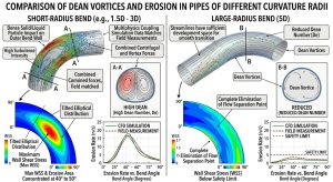
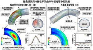
當高壓流體進入1.5D短半徑彎頭時,流體微觀質點受到強烈的離心力驅動。管中心區域的高速流體因動能較大,被強行推向彎頭的外彎壁(Extrados);同時,近壁面的低速流體受到壓力梯度與黏滯力的影響,沿著管壁周向向內彎壁(Intrados)回流。這種徑向與周向流動的疊加,在垂直於主流方向的橫截面上形成了兩股對稱且反向的螺旋狀漩渦,即工程流體力學中著名的迪安渦流(Dean Vortices)1。 When high-pressure fluid enters a 1.5D short-radius elbow, micro-fluid particles are driven by strong centrifugal forces. The high-speed fluid in the central region of the pipe, due to higher kinetic energy, is forced toward the extrados of the elbow; simultaneously, the low-speed fluid near the wall is influenced by pressure gradients and viscous forces, flowing back circumferentially towards the intrados. The superposition of these radial and circumferential flows forms two symmetrical and counter-rotating spiral vortices on the cross-section perpendicular to the mainstream direction, known in engineering fluid mechanics as Dean Vortices1.
迪安渦流的強度可由無因次的迪安數(Dean Number, De)加以量化,其定義為雷諾數(Reynolds Number, Re)與曲率比平方根的乘積: The intensity of Dean Vortices can be quantified by the dimensionless Dean Number (De), defined as the product of the Reynolds Number (Re) and the square root of the curvature ratio:
De=Re√(D/2Rc)
式中,D 為管徑, Rc為彎曲曲率半徑。由公式可知,曲率半徑 Rc 越小(如1.5D),迪安數越高。CFD數值模擬證實,1.5D彎頭極小的曲率半徑會將迪安數推至極端水準,誘發強烈的渦流切換效應(Swirl-Switching Effects)1。這種效應導致邊界層在彎頭下游發生嚴重的流場分離(Flow Separation),並產生大面積的逆壓梯度與迴流區。 Where D is the pipe diameter and Rc is the radius of curvature. The formula indicates that the smaller the radius of curvature Rc (e.g., 1.5D), the higher the Dean number. CFD numerical simulations confirm that the extremely small curvature radius of a 1.5D elbow pushes the Dean number to extreme levels, inducing intense swirl-switching effects1. This effect causes severe flow separation of the boundary layer downstream of the elbow, generating massive adverse pressure gradients and recirculation zones.
在多物理場耦合軟體(如COMSOL與流體體積法VOF結合離散元素法DEM)的模擬中,高湍流強度的流體或固/液相顆粒會受到離心力與渦流的雙重作用,直接且密集地撞擊彎頭外側壁面。模擬數據與現場實測高度吻合,確認了最大剪應力與沖蝕區通常集中於彎頭外彎壁40°至50°的角度位置,並呈現傾斜的橢圓形分佈5。相比之下,5D大半徑彎管透過降低迪安數,使流線獲得足夠的發展空間進行平滑過渡,徹底消除了流場分離點,並將壁面剪應力(Wall Shear Stress, WSS)降至安全極限值以下1。 In simulations using multiphysics coupling software (such as COMSOL and the Volume of Fluid (VOF) method combined with the Discrete Element Method (DEM)), high-turbulence fluid or solid/liquid phase particles are subjected to the dual action of centrifugal forces and vortices, directly and densely impacting the outer wall of the elbow. Simulation data highly aligns with field measurements, confirming that the maximum shear stress and erosion zones are typically concentrated at a 40° to 50° angle on the elbow’s extrados, presenting a slanted elliptical distribution5. In contrast, the 5D large-radius bend reduces the Dean number, providing sufficient developmental space for streamlines to transition smoothly, completely eliminating the flow separation point, and reducing the Wall Shear Stress (WSS) below safe limits1.
2.2 磁鐵礦溶解熱力學與電化學反應 / 2.2 Thermodynamics of Magnetite Dissolution and Electrochemical Reactions
伴隨上述物理流場的惡化,流體加速腐蝕(FAC)的化學反應也隨之加劇。FAC並非單純的機械磨損,而是化學溶解與流體沖刷相互促進的耦合過程。在碳鋼與低合金鋼管線暴露於高溫純水的環境中,金屬表面會自發形成一層緻密的保護性氧化膜(主要為磁鐵礦Fe3O4 或鐵鉻尖晶石 Fe3-xCrxO4)1。其基礎熱力學反應方程式為: Accompanying the deterioration of the aforementioned physical flow field, the chemical reactions of Flow-Accelerated Corrosion (FAC) also intensify. FAC is not mere mechanical wear but a coupled process where chemical dissolution and fluid erosion mutually promote each other. When carbon steel and low-alloy steel piping are exposed to high-temperature pure water environments, a dense protective oxide film (primarily magnetite Fe3O4 or iron-chromium spinel Fe3-xCrxO4) spontaneously forms on the metal surface1. The basic thermodynamic reaction equation is:
3Fe+4H2O→Fe3O4+4H2
在弱鹼性且溶氧極低(< 5 ppb)的鍋爐給水與蒸汽系統中,磁鐵礦的溶解度與溫度呈現高度的非線性關係。研究表明,在130°C至150°C的溫度區間內,磁鐵礦還原溶解為亞鐵離子(如Fe2+、Fe(OH)+)的溶解度達到峰值。此時,熱力學驅動力最強,管壁減薄的潛在風險最為嚴重1。若流體呈現前述的高流速與強湍流狀態,將打破氧化層生成與溶解的動態平衡,使得保護膜不斷變薄甚至發生脆性剝落,導致裸露的金屬基體持續受到腐蝕攻擊1。 In slightly alkaline boiler feedwater and steam systems with extremely low dissolved oxygen (< 5 ppb), the solubility of magnetite exhibits a highly non-linear relationship with temperature. Studies show that between 130°C and 150°C, the reductive dissolution of magnetite into ferrous ions (such as Fe2+, Fe(OH)+) reaches its peak solubility. At this point, the thermodynamic driving force is at its strongest, posing the most severe risk for wall thinning1. If the fluid exhibits the previously mentioned high-velocity and highly turbulent states, the dynamic equilibrium between oxide layer formation and dissolution is broken, causing the protective film to continuously thin or even undergo brittle spallation, leaving the exposed metal matrix subjected to continuous corrosive attacks1.
2.3 邊界層質傳限制與Sanchez-Caldera模型 / 2.3 Boundary Layer Mass Transfer Limitations and the Sanchez-Caldera Model
氧化層的溶解反應速率實質上受限於邊界層的對流質傳機制。為了精確量化FAC的減薄速率,學界廣泛採用Sanchez-Caldera質傳模型。該模型假設氧化層在穩態下的生長速率與溶解速率相等,從而推導出金屬減薄率的解析解: The dissolution reaction rate of the oxide layer is fundamentally limited by the convective mass transfer mechanism of the boundary layer. To accurately quantify the FAC thinning rate, academia widely adopts the Sanchez-Caldera mass transfer model. This model assumes that the growth rate and dissolution rate of the oxide layer are equal under steady-state conditions, thereby deriving the analytical solution for the metal thinning rate:
dm/dt=θ(Ce-C∞ )/[1/kf +(1-f)(1/K+d/Deff ) ]
在此方程式中,Ce 為氧化物在金屬-氧化物界面的平衡濃度, C∞為主流體中的濃度,θ 為孔隙率函數, kf為界面反應速率常數,d 為氧化膜厚度,Deff 為有效擴散係數,而 K 則代表流體對流質傳係數(Convective Mass Transfer Coefficient)1。 In this equation, Ce is the equilibrium concentration of the oxide at the metal-oxide interface, C∞ is the concentration in the bulk fluid, θ is the porosity function, kf is the interface reaction rate constant, d is the oxide film thickness, Deff is the effective diffusion coefficient, and K represents the convective mass transfer coefficient of the fluid1.
對流質傳係數 K 可進一步透過無因次的薛伍德數(Sherwood Number, Sh)進行求解: The convective mass transfer coefficient K can be further solved via the dimensionless Sherwood Number (Sh):
Sh=(K⋅dh)/Di =a⋅Reb⋅Scc
其中, Re為雷諾數,Sc 為施密特數(Schmidt Number),a,b,c 為經驗常數。1.5D彎頭所引發的高湍流與流場分離,極大地壓縮了流體邊界層厚度,導致邊界層內的濃度梯度急遽攀升,進而使質傳係數 K 呈現指數級增長,徹底放大了腐蝕速率1。 Where Re is the Reynolds Number, Sc is the Schmidt Number, and a,b,c are empirical constants. The high turbulence and flow separation induced by the 1.5D elbow vastly compress the fluid boundary layer thickness, leading to a sharp rise in the concentration gradient within the boundary layer, which in turn causes the mass transfer coefficient K to grow exponentially, thoroughly magnifying the corrosion rate1.
2.4 CHECWORKS預測模型與幾何增強因子 / 2.4 CHECWORKS Prediction Model and Geometry Factors
為了解決複雜幾何形狀對局部質傳的放大效應,美國電力研究院(EPRI)在其開發的FAC預測與管理軟體(如CHECWORKS)中,引入了「幾何因子」(Geometry Factor, GF)的概念。該因子將直管的質傳速率設定為基準值1.0。根據多項實驗與CFD數據擬合,傳統1.5D彎頭的幾何增強因子依據具體操作參數的不同,高達3.7至13不等1。這意味著在完全相同的水化學與熱力學條件下,1.5D彎頭的減薄率可能是直管段的數倍甚至十倍以上。 To address the amplification effect of complex geometries on local mass transfer, the Electric Power Research Institute (EPRI) introduced the concept of a “Geometry Factor” (GF) in its developed FAC prediction and management software (such as CHECWORKS). This factor sets the mass transfer rate of a straight pipe at a baseline value of 1.0. Based on multiple experiments and CFD data fitting, the geometry enhancement factor for traditional 1.5D elbows ranges from 3.7 up to 13, depending on specific operational parameters1. This implies that under identical water chemistry and thermodynamic conditions, the thinning rate of a 1.5D elbow could be several times or even over ten times higher than that of a straight pipe segment.
透過將1.5D彎頭升級為3D或5D冷作彎管,流場的平緩化實質上壓低了該區域的幾何因子,使 K 值大幅下降。這種流態改善不僅確保流速維持在臨界極限值以下,有效防止氧化層的脆性剝落,更將FAC/LDI的減薄率重新控制在長效運轉的安全邊界內1。 By upgrading the 1.5D elbow to a 3D or 5D cold bend, the flattening of the flow field substantially drives down the geometry factor in that region, causing the K value to drop significantly. This flow state improvement not only ensures that the flow velocity remains below critical limits, effectively preventing the brittle spallation of the oxide layer, but also brings the FAC/LDI thinning rate back within the safe boundaries of long-term operation1.
| 比較參數 / Comparison Parameter | 1.5D 電銲彎頭 / 1.5D Butt-Welded Elbow | 3D / 5D 冷作彎管 / 3D / 5D Cold Bend | 物理意義與影響 / Physical Meaning and Impact |
| 迪安數 (De) / Dean Number (De) | 極高 / Extremely High | 低 / Low | 決定二次流強度與流場分離的規模 / Determines the intensity of secondary flows and the scale of flow separation |
| 壁面剪應力 (WSS) / Wall Shear Stress (WSS) | 高頻波動、極大值集中 / High-frequency fluctuations, maximum values concentrated | 平穩、低幅 / Steady, low amplitude | 直接影響保護性氧化膜的剝落機率 / Directly affects the probability of protective oxide film spallation |
| 對流質傳係數 (K) / Convective Mass Transfer Coefficient (K) | 極大(邊界層極薄) / Extremely large (extremely thin boundary layer) | 低至中等(邊界層穩定) / Low to moderate (stable boundary layer) | 控制Sanchez-Caldera模型中的溶解傳輸率 / Controls the dissolution transport rate in the Sanchez-Caldera model |
| CHECWORKS 幾何因子 / CHECWORKS Geometry Factor | 3.7至13 / 3.7 to 13 | 趨近於1.0 / Approaches 1.0 | 決定壽命預測模型中的局部減薄放大倍率 / Determines the local thinning amplification ratio in lifespan prediction models |
除了流體側的沖蝕威脅,管材自身的冶金結構在極端環境下的退化,更是傳統銲接彎頭面臨的另一大挑戰,這將在下一章節進行深入剖析。Beyond the erosion threats from the fluid side, the degradation of the piping material’s own metallurgical structure in extreme environments presents another major challenge for traditional welded elbows, which will be deeply analyzed in the next section.
三、材料冶金退化與第四型潛變破裂(Type IV Cracking)機制 / III. Material Metallurgical Degradation and Type IV Creep Cracking Mechanisms
CCPP主蒸汽管線之所以能在超臨界狀態下長期服役,高度仰賴先進合金鋼的微觀組織設計。然而,傳統彎頭的現場銲接工法在物理結構上直接破壞了這種微觀完整性,成為管線系統中最具威脅的潛藏風險。The reason CCPP main steam piping can serve long-term under supercritical conditions highly relies on the microstructural design of advanced alloy steels. However, the on-site welding methods of traditional elbows physically destroy this microstructural integrity, turning it into the most threatening hidden risk in the piping system.
3.1 P9X系列合金鋼之微觀強化機制 / 3.1 Microstructural Strengthening Mechanisms of P9X Series Alloy Steels
為對抗高溫潛變與氧化,現代高能管線廣泛採用潛變強度強化鐵素體鋼(Creep Strength Enhanced Ferritic Steels, CSEF),如 ASTM A335 P91、P92 與 P93。這類9%鉻系合金鋼在製造過程中,需經過約1040°C–1060°C的正常化(Normalizing)處理以充分奧氏體化,隨後空冷形成麻田散鐵,最後進行約760°C的高溫回火(Tempering)1。 To combat high-temperature creep and oxidation, modern high-energy piping widely adopts Creep Strength Enhanced Ferritic Steels (CSEF), such as ASTM A335 P91, P92, and P93. During manufacturing, these 9% chromium alloy steels undergo normalizing treatment at approximately 1040°C–1060°C for full austenitization, followed by air cooling to form martensite, and finally undergo high-temperature tempering at around 760°C1.
最終獲得的微觀組織為具有高位錯密度的回火麻田散鐵(Tempered Martensite)板條。其高溫強度的來源主要依賴雙重析出強化機制:第一,富鉻的M23C6 型碳化物沿著原奧氏體晶界與板條邊界大量析出,穩定邊界結構;第二,極細小、奈米級的 MX 型碳氮化物(如鈮、釩的碳氮化物 Nb/V(C,N))彌散分佈於板條內部。這些析出物透過強大的齊納釘紮效應(Zener Pinning Effect),有效阻礙了高溫下位錯的滑移(Dislocation Glide)與晶界滑移(Grain Boundary Sliding),賦予材料卓越的高溫潛變抗力1。 The final microstructure obtained consists of tempered martensite laths with a high dislocation density. The source of its high-temperature strength primarily relies on a dual precipitation strengthening mechanism: first, chromium-rich M23C6 type carbides precipitate abundantly along prior austenite grain boundaries and lath boundaries, stabilizing the boundary structure; second, ultra-fine, nano-scale MX type carbonitrides (e.g., niobium and vanadium carbonitrides Nb/V(C,N)) are uniformly dispersed within the laths. Through the strong Zener Pinning Effect, these precipitates effectively hinder dislocation glide and grain boundary sliding at high temperatures, granting the material outstanding high-temperature creep resistance1.
3.2 熱影響區(HAZ)之冶金退化與 ICHAZ/FGHAZ 特性 / 3.2 Metallurgical Degradation of the Heat-Affected Zone (HAZ) and ICHAZ/FGHAZ Characteristics
然而,1.5D彎頭作為獨立的管件,必須依賴兩道環向銲接(Girth Welds)與直管相連。在電銲熱循環中,母材會依據距離熔池的遠近,經歷不同的峰值溫度區間,從而形成粗晶熱影響區(CGHAZ)、細晶熱影響區(FGHAZ)與相間臨界熱影響區(ICHAZ)1。 However, as a standalone fitting, the 1.5D elbow must rely on two girth welds to connect with straight pipes. During the arc welding thermal cycle, the base metal experiences different peak temperature intervals depending on the distance from the weld pool, forming a Coarse-Grained Heat-Affected Zone (CGHAZ), a Fine-Grained Heat-Affected Zone (FGHAZ), and an Intercritical Heat-Affected Zone (ICHAZ)1.
對於 P9X 系列合金而言,最為致命的次區域是 FGHAZ 與 ICHAZ。這兩個區域在銲接過程中所經歷的峰值溫度,恰好落在下臨界相變點(AC1)與上臨界相變點(AC3)之間的狹窄帶內3。在該溫度區間,材料經歷了「不完全的奧氏體化」(Partial Austenitization)。微觀下,原本提供強大釘紮作用的微細 MX 碳氮化物發生了部分溶解與粗化。更糟糕的是,在隨後的快速冷卻過程中,該區域未能恢復原始的高強度麻田散鐵板條,而是轉變為硬度較低、位錯密度大幅下降且晶粒異常細化的軟弱多邊形鐵素體(Polygonal Ferrite)組織3。 For the P9X series alloys, the most fatal sub-regions are the FGHAZ and ICHAZ. The peak temperatures these two zones endure during the welding process fall exactly within the narrow band between the lower critical transformation point (AC1) and the upper critical transformation point (AC3)3. In this temperature range, the material undergoes “Partial Austenitization.” Microscopically, the fine MX carbonitrides that originally provided a strong pinning effect undergo partial dissolution and coarsening. Worse still, during the subsequent rapid cooling process, this region fails to recover the original high-strength martensite laths; instead, it transforms into a weak polygonal ferrite structure with lower hardness, vastly reduced dislocation density, and abnormally fine grains3.
3.3 潛變空洞成核與 Rice-Tracey 模型 / 3.3 Creep Cavity Nucleation and the Rice-Tracey Model
當帶有 HAZ 的管線進入高溫、高壓的服役階段,這種微觀組織的劣勢將被急速放大。在高壓蒸汽產生的內壓應力以及管線熱膨脹受阻產生的軸向力作用下,彎頭轉折處會形成嚴重的多軸應力拘束(Triaxial Stress Constraint)狀態6。 When piping containing a HAZ enters the high-temperature, high-pressure service stage, the disadvantages of this microstructure are rapidly magnified. Under the internal pressure stresses generated by high-pressure steam and the axial forces produced by restricted thermal expansion, severe triaxial stress constraint states form at the elbow transitions6.
在這種拘束與高溫的長期作用下,退化區域(特別是 FGHAZ)內殘存的析出物會迅速失去熱力學穩定性,例如富鉬、鎢的拉夫斯相(Laves Phase)會發生異常的長大與聚合,徹底喪失了阻礙晶界移動的能力。根據金屬斷裂力學中的 Rice-Tracey 空孔成長模型,微觀蠕變空孔(Creep Cavities)會優先沿著這些失去保護的晶界迅速成核(Nucleation),並隨著應力集中效應不斷成長(Growth)。Under the long-term effects of this constraint and high temperatures, the remaining precipitates in the degraded zones (especially the FGHAZ) quickly lose thermodynamic stability; for example, the molybdenum and tungsten-rich Laves Phase undergoes abnormal growth and agglomeration, completely losing the ability to impede grain boundary movement. According to the Rice-Tracey void growth model in metal fracture mechanics, microscopic creep cavities will rapidly nucleate preferentially along these unprotected grain boundaries and continue to grow due to stress concentration effects.
隨著時間推移,這些微觀空孔會相互連結,演化成宏觀的微裂紋。這種損傷累積的過程極其隱蔽,管件外表幾乎不會產生任何宏觀的膨脹或塑性變形。最終,管線會在遠低於設計壽命(例如數萬小時內)的情況下,於 HAZ 區域發生毫無預警的巨觀脆性斷裂,這即是工程界公認的「第四型潛變破裂」(Type IV Creep Cracking)1。 Over time, these microscopic cavities interconnect, evolving into macroscopic micro-cracks. This damage accumulation process is extremely concealed; the outer surface of the fitting exhibits almost no macroscopic swelling or plastic deformation. Ultimately, the piping will experience an unheralded macroscopic brittle fracture in the HAZ region well below its design life (e.g., within tens of thousands of hours). This is universally recognized in engineering as “Type IV Creep Cracking”1.
3.4 現場銲後熱處理(PWHT)之嚴苛風險與容錯率 / 3.4 Severe Risks and Fault Tolerance of On-Site Post-Weld Heat Treatment (PWHT)
為嘗試修復銲接過程對 P9X 合金造成的損害,規範強制要求進行銲後熱處理(Post-Weld Heat Treatment, PWHT),旨在消除高達 450 Hv 的銲縫硬度、釋放殘餘應力並恢復材料韌性。然而,P9X 合金的 PWHT 溫度通常必須精確控制在 730°C 至 760°C 的狹窄區間內4。 In an attempt to repair the damage caused to the P9X alloy by the welding process, standards mandate Post-Weld Heat Treatment (PWHT), aimed at eliminating weld hardness up to 450 Hv, relieving residual stress, and restoring material toughness. However, the PWHT temperatures for P9X alloys must typically be precisely controlled within a narrow range of 730°C to 760°C4.
在發電廠複雜且高空作業的現場環境中,精確控溫面臨極大挑戰。若現場保溫毯包覆不均或加熱片控制不佳,導致溫度偏差僅 15°C,或不慎超過母材的 AC1 溫度(約 810°C),銲縫金屬與母材的微觀結構將遭到不可逆的毀滅性破壞,其潛變破裂強度可能瞬間銳減 50% 以上。這種極低的容錯率,使得傳統1.5D彎頭在施工品質管控上面臨極大的不確定性。In the complex and high-altitude field environment of a power plant, precise temperature control faces immense challenges. If on-site insulation blankets are wrapped unevenly or heating pads are poorly controlled, resulting in a temperature deviation of just 15°C, or inadvertently exceeding the base metal’s AC1 temperature (approx. 810°C), the microstructure of the weld metal and base metal will suffer irreversible and devastating destruction, with its creep rupture strength potentially plummeting by over 50% instantly. This extremely low fault tolerance subjects traditional 1.5D elbows to massive uncertainties in construction quality control.
相比之下,採用無銲縫一體成型的3D/5D冷作彎管,從物理層面直接拔除了 HAZ 與現場 PWHT 的需求,是根絕 Type IV 裂紋的最有效策略1。消除銲縫不僅在冶金上具有決定性意義,在宏觀的結構力學表現上,冷作彎管同樣展現出截然不同的優勢。 By comparison, adopting seamless, integrally-formed 3D/5D cold bends physically removes the need for HAZ and on-site PWHT altogether, serving as the most effective strategy to eradicate Type IV cracks1. Eliminating welds is not only of decisive significance metallurgically but also allows cold bends to exhibit distinctly superior advantages in macroscopic structural mechanics performance.
四、結構力學最佳化:基於 ASME B31J 與 B31.1 之系統評估 / IV. Structural Mechanics Optimization: Systematic Evaluation Based on ASME B31J and B31.1
延續冶金結構的探討,3D/5D冷作彎管的引入更在管線系統的宏觀結構力學上展現出絕對的優勢。這些優勢在 ASME B31J《管線組件應力強化因子與柔性係數》(Stress Intensification Factors, Flexibility Factors, and Their Determination for Metallic Piping Components)規範中得到了精確的數學量化。Continuing the discussion on metallurgical structures, the introduction of 3D/5D cold bends also demonstrates absolute superiority in the macroscopic structural mechanics of the piping system. These advantages are precisely quantified mathematically in the ASME B31J standard (“Stress Intensification Factors, Flexibility Factors, and Their Determination for Metallic Piping Components”).
4.1 應力強化因子(SIF)與柔性特徵值的理論推導 / 4.1 Theoretical Derivation of Stress Intensification Factors (SIF) and Flexibility Characteristics
在管線應力分析中,彎頭因其曲率特性,在彎矩作用下會發生橫截面的橢圓化(Ovalization),導致實際承受的最大應力遠大於根據簡單梁理論(Beam Theory)計算得出的應力。為了修正這一偏差,ASME B31J 規範引入了應力強化因子(SIF, 代號 i)與柔性因子(Flexibility Factor, 代號 k)12。 In piping stress analysis, due to their curvature characteristics, elbows undergo cross-sectional ovalization under bending moments, causing the actual maximum stress sustained to be far greater than the stress calculated based on simple Beam Theory. To correct this deviation, the ASME B31J standard introduces the Stress Intensification Factor (SIF, denoted as i) and the Flexibility Factor (denoted as k)12.
這些因子的計算基礎為無因次的柔性特徵值(Flexibility Characteristic, h),其公式定義為: The calculation foundation for these factors is the dimensionless Flexibility Characteristic (h), with its formula defined as:
h=T⋅R1/r22
式中,T 為管件公稱壁厚(Nominal wall thickness),R1 為彎曲半徑(Bend radius),r2 為平均管半徑(Mean pipe radius)12。 Where T is the fitting’s nominal wall thickness, R1 is the bend radius, and r2 is the mean pipe radius12.
ASME B31J 進一步區分了空間中的方向性 SIF,包括: ASME B31J further distinguishes directional SIFs in space, including:
- 平面內應力強化因子(In-plane SIF):ii=0.9/h2/3
- 平面外應力強化因子(Out-of-plane SIF): io=0.75/h2/3
- 柔性因子(Flexibility Factor): k=1.65/h(規範強制規定,上述因子的計算結果若小於0,皆以 1.0 計算)12。 (The standard strictly mandates that if the calculated result of the above factors is less than 1.0, it must be evaluated as 1.0)12.
4.2 1.5D與5D彎管之應力稀釋與柔性補償對比 / 4.2 Comparison of Stress Dilution and Flexibility Compensation between 1.5D and 5D Bends
從 h 值的公式可以清晰看出,柔性特徵值與彎曲半徑 R1 呈現正比關係。 對於1.5D短半徑彎頭,由於 R1 極小,計算得出的 h 值偏低。這使得 h2/3 成為一個極小的分母,導致 ii 與 io 數值急遽攀升。這意味著在承受相同的外部彎矩時,1.5D彎頭會產生極高的局部應力集中13。此外,傳統 B16.9 規格品彎頭的出廠角度被嚴格固定為 45° 或 90°,但在電廠配管實務中,為了滿足 1° 到 3° 的洩水坡度(Drainage slopes)要求,現場銲工往往需要施加強迫組裝應力(Forced Fit-up Stresses)。這些殘餘應力疊加在 SIF 極高的端點銲縫上,極大削弱了系統的疲勞容限(Fatigue Tolerance)。 From the h value formula, it is clear that the flexibility characteristic is directly proportional to the bend radius R1. For a 1.5D short-radius elbow, because R1 is extremely small, the calculated h value is low. This makes h2/3 a very small denominator, causing the ii and io values to skyrocket. This implies that when subjected to the same external bending moment, a 1.5D elbow generates exceedingly high local stress concentrations13. Furthermore, the factory angles of traditional B16.9 standard elbows are strictly fixed at 45° or 90°. However, in power plant piping practices, to meet 1° to 3° drainage slope requirements, on-site welders often need to apply Forced Fit-up Stresses. These residual stresses superimpose on the highly SIF-concentrated end welds, drastically weakening the system’s Fatigue Tolerance.
反觀採用R=5D 的冷作彎管,其彎曲半徑擴大了三倍以上,使得 h 值顯著增加,計算所得的 SIF 值大幅下降,通常趨近於規範規定的最低極限值 1.018。平緩的曲率在幾何上稀釋了彎矩集中效應,有效壓低了持續應力(Sustained Stress)與熱膨脹應力(Thermal Expansion Stress)的峰值。 Conversely, using a cold bend with R=5D expands the bend radius by more than three times, causing a significant increase in the h value and a substantial drop in the calculated SIF values, typically approaching the standard’s minimum limit of 1.018. The gentle curvature geometrically dilutes the bending moment concentration effect, effectively suppressing the peaks of Sustained Stress and Thermal Expansion Stress.
更為關鍵的是,5D彎管因具有較低的 h 值分母,其柔性因子 k 顯著高於1.5D彎頭17。在 CAESAR II 或 AutoPIPE 等應力分析軟體的剛度矩陣計算中,較大的 k 值代表該管件具備卓越的變形補償能力。5D彎管如同一個強韌的彈簧,能夠柔性吸收管系因極端熱膨脹與收縮所產生的巨大位移,從而減少傳導至相連設備管嘴(Nozzle)或支吊架的反作用力,全面提升了管線系統的熱機械疲勞壽命與安全餘裕15。 Even more critically, because the 5D bend possesses a smaller h value as a denominator, its flexibility factor k is notably higher than that of a 1.5D elbow17. In stiffness matrix calculations of stress analysis software like CAESAR II or AutoPIPE, a larger k value indicates that the fitting possesses superior deformation compensation capabilities. A 5D bend acts like a robust spring, capable of flexibly absorbing massive displacements caused by extreme thermal expansion and contraction in the piping system, thereby reducing the reaction forces transmitted to connected equipment nozzles or supports, comprehensively enhancing the thermo-mechanical fatigue life and safety margins of the piping system15.
4.3 ASME B31.1 與 B16.49 規範下之製造挑戰與管控 / 4.3 Manufacturing Challenges and Control under ASME B31.1 and B16.49 Standards
儘管5D冷作彎管具備卓越的性能,但其製造過程需在環境溫度下進行金屬的大變形塑性加工,因此必須嚴格依循 ASME B31.1《動力配管規範》與 ASME B16.49《工廠製造之感應彎管》的標準要求,以確保品質無虞18。 Although 5D cold bends possess outstanding performance, their manufacturing process requires severe plastic deformation of metal at ambient temperatures. Therefore, it must strictly comply with the standard requirements of ASME B31.1 “Power Piping” and ASME B16.49 “Factory-Made Wrought Steel Buttwelding Induction Bends for Transportation and Distribution Systems” to ensure flawless quality18.
- 壁厚減薄(Wall Thinning)管控: 當彎徑比介於3≦RD≦5時,屬於緊密半徑冷作彎曲。彎管外彎壁承受極大的拉伸應變,必然發生壁厚減薄。根據 ASME B31.1 (Para 104.2.1) 的規定,彎曲後最薄處的實際壁厚必須大於或等於設計所需的最小壁厚 tm(包含腐蝕/沖蝕餘量)26。工程實務中,R=5D 的冷彎可能引發高達 12% 的局部減薄。因此,設計者必須在選用初始直管(母管)時,精確計算並預留足夠的名義壁厚(Nominal Thickness)餘裕。 Wall Thinning Control: When the bend radius ratio is between 3≦RD≦5, it classifies as a tight-radius cold bend. The outer wall (extrados) of the bend undergoes severe tensile strain, inevitably leading to wall thinning. According to ASME B31.1 (Para 104.2.1) regulations, the actual wall thickness at the thinnest point after bending must be greater than or equal to the minimum required design thickness tm (including corrosion/erosion allowances)26. In engineering practice, R=5D cold bending can induce up to 12% local thinning. Therefore, designers must precisely calculate and reserve sufficient Nominal Thickness margins when selecting the initial straight pipe (mother pipe).
- 扁平率/橢圓度(Ovality)控制: 彎曲過程中的塑性變形會導致管件橫截面產生扁平化。依據 ASME B16.49 等規範,最大允許橢圓度通常被限制在 8% 以內(部分嚴苛應用要求更低)18。若橢圓度超標,不僅會引發流體擾動,更會改變管件的慣性矩,使得前述的 SIF 與 k 因子分析失真。為此,製造廠通常需配備精密控制的內部芯棒(Mandrel)與數控設備以維持圓度。 Ovality / Flattening Control: Plastic deformation during the bending process causes the fitting’s cross-section to flatten. According to standards like ASME B16.49, the maximum allowable ovality is generally restricted to within 8% (some severe applications demand even lower limits)18. If ovality exceeds limits, it not only induces fluid disturbances but also alters the fitting’s moment of inertia, skewing the aforementioned SIF and k factor analyses. To prevent this, manufacturers must typically equip precision-controlled internal mandrels and CNC equipment to maintain roundness.
- 殘餘應力與次臨界彎後熱處理(PBHT): 冷作變形會在外半徑處積累極高的殘餘拉伸應力。對於 R=5D 的彎管,理論最大拉伸應變ε≈D/(2R) 約高達 10%。在含氧或高溫蒸汽的腐蝕環境中,高殘餘應力是誘發應力腐蝕裂紋(SCC)的關鍵因素。依據 ASME B31.1,為消除殘餘應力並恢復延展性,必須執行次臨界彎後熱處理(Post-Bending Heat Treatment, PBHT)。對 P91/P92 材料而言,將 PBHT 溫度精確控制於 705°C 至 760°C 之間,可在不破壞材料微觀強化析出相的前提下,完美消除冷作加工硬化,確保其長期潛變韌性1。 Residual Stress and Post-Bending Heat Treatment (PBHT): Cold deformation accumulates extremely high residual tensile stresses on the extrados. For an R=5D bend, the theoretical maximum tensile strain ε≈D/(2R) reaches up to approximately 10%. In corrosive environments containing oxygen or high-temperature steam, high residual stress is a key factor inducing Stress Corrosion Cracking (SCC). According to ASME B31.1, to eliminate residual stresses and restore ductility, subcritical Post-Bending Heat Treatment (PBHT) must be executed. For P91/P92 materials, precisely controlling the PBHT temperature between 705°C and 760°C flawlessly eliminates cold working hardening without destroying the material’s microstructural strengthening precipitates, ensuring its long-term creep toughness1.
經過工程設計與材料製造端的嚴格把關後,設備上線服役的實際狀態仍需依賴健全的在役檢驗機制來驗證。After strict quality controls at the engineering design and material manufacturing stages, the actual state of the equipment in service still relies on robust in-service inspection mechanisms for verification.
五、在役管線檢驗實務與預測評估:基於 API 570 與 NSAC-202L / V. In-Service Piping Inspection Practices and Predictive Evaluation: Based on API 570 and NSAC-202L
工程設計與材料優化的成效,最終必須透過嚴謹的在役檢驗數據予以確認。國際間針對石化與發電廠管線的完整性管理,廣泛採用美國石油協會的 API 570《在役管線檢驗規範》與美國電力研究院的 EPRI NSAC-202L 指南,作為狀態監測的準則7。 The effectiveness of engineering design and material optimization must ultimately be confirmed through rigorous in-service inspection data. For the integrity management of petrochemical and power plant piping globally, the American Petroleum Institute’s API 570 “Piping Inspection Code” and the Electric Power Research Institute’s EPRI NSAC-202L guidelines are widely adopted as condition monitoring standards7.
5.1 EPRI NSAC-202L 預測指引與 CML 選定 / 5.1 EPRI NSAC-202L Predictive Guidelines and CML Selection
為了防範 FAC,EPRI 開發的 NSAC-202L-R3 指南強調必須透過熱力學(溫度、蒸汽品質)、水化學(pH值、氧化還原電位 ORP)與流體動力學(流速、幾何形狀)的三重指標來篩選高風險區域,並建立狀態監測位置(Condition Monitoring Locations, CML)7。由於傳統 1.5D 彎頭具有高達 3.7 至 13 的幾何增強因子,在預測模型中無可避免地會被系統標記為極高風險的 CML,要求密集的追蹤檢測1。相對地,採用 5D 彎管後,因幾何因子的斷崖式下降,預測減薄率將大幅低於警戒值,從而合理降低了非破壞性檢測(NDT)的實施頻率與運維成本。 To prevent FAC, EPRI’s NSAC-202L-R3 guidelines emphasize screening high-risk areas and establishing Condition Monitoring Locations (CML) through a triple-indicator system: thermodynamics (temperature, steam quality), water chemistry (pH value, Oxidation-Reduction Potential ORP), and fluid dynamics (velocity, geometry)7. Since traditional 1.5D elbows possess geometry enhancement factors as high as 3.7 to 13, predictive models inevitably flag them as extreme-risk CMLs, requiring intensive tracking inspections1. In contrast, after adopting 5D bends, the steep drop in the geometry factor pushes predicted thinning rates well below warning thresholds, thereby rationally reducing the frequency of Non-Destructive Testing (NDT) and lowering Operations and Maintenance (O&M) costs.
5.2 API 570 超音波測厚(UT)與網格化檢測策略 / 5.2 API 570 Ultrasonic Thickness (UT) and Grid Inspection Strategies
針對被選定的 CML,API 570 規範定義了嚴謹的在役管線測厚與評估程序。對於具備沖蝕或 FAC 風險的彎管區域,常規的單點測厚極易遺漏局部坑蝕或減薄斑塊。因此,規範建議實施系統化的網格化超音波測厚(Grid UT)27。 For selected CMLs, the API 570 standard defines rigorous procedures for in-service piping thickness measurements and evaluations. For elbow regions at risk of erosion or FAC, conventional single-point thickness measurements can easily miss localized pitting or thinned patches. Hence, the standard recommends implementing systematic Grid Ultrasonic Thickness (Grid UT) scanning27.
標準的檢測程序要求在彎管表面建立 1吋 x 1吋(1″ x 1″)的檢測網格。考量到重力、液滴沉降與二次流效應,檢測重點需集中於流體最易衝擊的外彎壁,以及水平管線彎曲段的底部(即 5 點鐘至 7 點鐘方向的帶狀區域)33。透過先進的相控陣列超音波(PAUT)或常規 UT,檢驗員能繪製出精確的剩餘壁厚分佈圖(Thickness Profile)36。 Standard inspection procedures mandate establishing a 1-inch by 1-inch (1″ x 1″) inspection grid over the elbow’s surface. Considering gravity, droplet settling, and secondary flow effects, inspections must focus on the extrados—the area most susceptible to fluid impact—as well as the bottom of horizontal piping bends (i.e., the band between the 5 o’clock and 7 o’clock positions)33. Using advanced Phased Array Ultrasonic Testing (PAUT) or conventional UT, inspectors can map out highly accurate remaining Thickness Profiles36.
5.3 短期與長期腐蝕率計算及剩餘壽命(RL)決策 / 5.3 Short-Term and Long-Term Corrosion Rate Calculations and Remaining Life (RL) Decisions
取得測量數據後,API 570 強制要求計算兩項關鍵指標,以準確捕捉管線的退化動態27: Upon acquiring measurement data, API 570 strictly requires calculating two key metrics to accurately capture the piping’s degradation dynamics27:
- 長期腐蝕率(LTCR, Long-Term Corrosion Rate): Long-Term Corrosion Rate (LTCR)
CRLT=(tinitial-tactual)/TLT
代表管線自初始安裝(或有紀錄之最早期)至今的總體退化趨勢27。 Represents the overall degradation trend of the piping from its initial installation (or earliest reliable record) to the present27.
- 短期腐蝕率(STCR, Short-Term Corrosion Rate): Short-Term Corrosion Rate (STCR):
CRST=(tprevious-tactual)/TST
代表前次檢測與本次檢測之間的減薄速率。STCR 的飆高通常預示著系統近期發生了製程異常(例如流速突增或 pH 值失控),導致保護性氧化膜遭到破壞。Represents the thinning rate between the previous and current inspections. A spike in STCR usually indicates a recent process anomaly in the system (e.g., sudden flow velocity surges or pH control failures), causing the protective oxide film to break down.
為確保安全絕對性,API 570 規定在計算剩餘壽命(Remaining Life, RL)時,必須採用 LTCR 與 STCR 兩者中的較大值(即 CRgoverning): To ensure absolute safety, API 570 dictates that when calculating Remaining Life (RL), the higher (more conservative) value between the LTCR and STCR (i.e., CRgoverning) must be used:
RL=(tactual-tmin)/(CRgoverning )
其中,tmin 為 ASME B31.1 或 B31.3 規定的壓力設計最小壁厚27。規範同時設立了強制性的檢驗上限,如下一次檢驗時間不得超過剩餘壽命的一半( RL/2),且對於高風險的 Class 1 管線,最高檢驗間隔不得超過 5 年(外部)或 10 年(測厚)。 Where tmin is the minimum required pressure design wall thickness per ASME B31.1 or B31.327. The standard simultaneously sets mandatory inspection interval caps, dictating that the next inspection date must not exceed half the remaining life (RL/2); for high-risk Class 1 piping, the maximum interval must not exceed 5 years (external) or 10 years (thickness).
這些規範與預測指引在實際電廠的應用中,具體成效為何?下文將以實際案例進行說明。What are the tangible outcomes of applying these standards and predictive guidelines in actual power plants? The following section illustrates this with a real-world case study.
六、CCPP廠實際應用成效評估與深度洞見 / VI. Practical Application Effectiveness Evaluation and Deep Insights in CCPP Plants
在某典型 CCPP 廠的實務維護案例中,廠方完整經歷了前述的退化風險與改善歷程。該廠原有的 P91 主蒸汽管線大量採用 1.5D 銲接彎頭,在歷經數年的頻繁起停調度後,API 570 UT 檢測數據顯示,多處 1.5D 彎頭外側 40°–50° 處的 STCR 出現異常飆升現象;同時,針對環向銲縫的 PAUT 檢測,亦發現 ICHAZ 區域內部開始出現微弱的蠕變空孔反射回波,顯示 Type IV 潛變裂紋正處於萌生初期。In a practical maintenance case study of a typical CCPP plant, the facility experienced the full lifecycle of the aforementioned degradation risks and improvement processes. The plant’s original P91 main steam piping heavily utilized 1.5D welded elbows. After years of frequent start-stop scheduling, API 570 UT inspection data revealed an abnormal spike in STCR at the 40°–50° extrados positions of multiple 1.5D elbows; simultaneously, PAUT inspections of the girth welds detected faint reflective echoes of creep cavities within the ICHAZ regions, indicating that Type IV creep cracks were in their initial nucleation stages.
廠方針對此一高風險狀態,果斷採取系統化改善策略,將高應力轉折處的 1.5D 彎頭與相連短直管一併切除,全面替換為符合 ASME B16.49 規範的 5D 冷作彎管(包含嚴格的 PBHT 與 12% 壁厚補償)。Facing this high-risk situation, plant management decisively adopted a systematic improvement strategy. They excised the 1.5D elbows at high-stress transitions along with their connected short straight pipes, comprehensively replacing them with 5D cold bends compliant with the ASME B16.49 standard (including strict PBHT and 12% wall thickness compensation).
經過為期兩年的後續追蹤,成效評估展現出極具指標意義的數據變化: After two years of follow-up tracking, the effectiveness evaluation demonstrated highly indicative data shifts:
- 沖蝕率斷崖式下降:5D彎管區域的 STCR 與 LTCR 雙雙降至接近零的基礎腐蝕率,證明流場平滑化成功保護了磁鐵礦層。 Steep Drop in Erosion Rates: Both the STCR and LTCR in the 5D bend regions fell to near-zero baseline corrosion rates, proving that flow field smoothing successfully protected the magnetite layer.
- 應力解除與無缺陷化:消除了應力集中區的環向銲縫,徹底移除了 Type IV 裂紋的成核點。 Stress Relief and Defect Elimination: Removing the girth welds in stress concentration zones completely eradicated the nucleation points for Type IV cracks.
- 剩餘壽命極大化:依據 API 570 計算,該區段管線的 RL 延長了數十萬小時,大幅超過了電廠的預定除役年限。 Maximization of Remaining Life: Calculated per API 570, the RL of this piping segment was extended by hundreds of thousands of hours, vastly exceeding the plant’s scheduled decommissioning timeline.
此一成功案例不僅印證了理論數據,更進一步牽動了建廠與營運端的整體決策思維。This successful case not only corroborates theoretical data but further drives the overarching decision-making philosophy on both the construction and operational fronts.
七、實務工程與營運管理決策分析 / VII. Practical Engineering and Operations Management Decision Analysis
基於上述的案例成效,在將1.5D對銲彎頭替換為3D/5D冷作彎管的過程中,實質上牽涉到電廠業主營運、EPC統包商設計、現場施工工法以及技術團隊的協同。針對這四個維度,以下進行深度的實務探討: Based on the case results above, replacing 1.5D butt-welded elbows with 3D/5D cold bends substantially involves the synergy of power plant owner operations, EPC (Engineering, Procurement, and Construction) contractor designs, on-site construction methods, and technical teams. Deep practical discussions across these four dimensions are provided below:
7.1 CCPP廠業主之維護管理及營運決策 / 7.1 Maintenance Management and Operations Decisions for CCPP Plant Owners
對於CCPP廠業主而言,高能管線的可靠度直接關乎全壽命週期成本(Life Cycle Cost, LCC)與機組運轉的絕對安全性1。 For CCPP plant owners, the reliability of high-energy piping directly impacts the Life Cycle Cost (LCC) and the absolute safety of unit operations1.
- 降低檢測頻率與成本:傳統5D彎頭因極高的流動加速腐蝕風險,通常被系統判定為高風險監測點(CML),需頻繁執行昂貴的API 570網格化超音波測厚(Grid UT)。改用3D/5D彎管後,因幾何因子的斷崖式下降,實質消除了大面積減薄隱患,得以降級巡檢頻率並節省大筆NDT(非破壞性檢測)維護費用。 Reducing Inspection Frequency and Costs: Traditional 1.5D elbows, due to their extremely high FAC risk, are typically classified by systems as high-risk CMLs, necessitating frequent and expensive API 570 Grid UT scanning. Switching to 3D/5D bends drives geometry factors off a cliff, virtually eliminating the threat of large-area thinning, allowing for downgraded inspection frequencies and saving substantial NDT maintenance expenses.
- 解除壽命桎梏:P9X高能管線在原本長達20萬小時的設計壽命內,1.5D彎頭所伴隨的兩道環向銲縫不可逆轉地成為系統最脆弱的物理環節,是Type IV裂紋的溫床。業主從營運決策上導入無銲縫的冷作彎管,等於徹底排除了因無預警爆管導致機組長期非計畫性停機(Outage)的災難性風險,真正實現資產壽命極大化。 Removing Lifespan Shackles: Within the original 200,000-hour design life of P9X high-energy piping, the two girth welds accompanying 1.5D elbows irreversibly become the system’s most fragile physical links and hotbeds for Type IV cracks. By incorporating seamless cold bends into operations decisions, owners completely eradicate the catastrophic risks of long-term unplanned outages caused by unexpected pipe bursts, truly maximizing asset lifespan.
7.2 EPC承包商設計單位之空間排列與實務考量 / 7.2 Spatial Arrangement and Practical Considerations for EPC Contractor Design Units
EPC(設計採購施工統包)單位在建廠初期,往往會因為廠房空間極端受限與管架(Pipe Rack)佈局緊湊,而傾向選用體積小巧的1.5D短半徑彎頭1。然而,這在後續實務上會遭遇嚴重的工程瓶頸: In the early plant construction stages, EPC contractors often lean toward compact 1.5D short-radius elbows due to extreme spatial constraints and tight Pipe Rack layouts1. However, this leads to severe engineering bottlenecks in later practices:
- 僵化的幾何限制與強迫組裝應力:標準9規格品的1.5D彎頭,出廠角度被嚴格固定為45°或90°。但在電廠配管實務中,為了滿足1°到3°的洩水坡度(Drainage slopes)要求,現場銲工往往必須在銲縫對接處進行人為微調與拉扯,強行誘發極大的「強迫組裝應力」(Forced Fit-up Stresses)。1. Rigid Geometric Constraints and Forced Fit-up Stresses: The factory angles of standard B16.9 1.5D elbows are strictly fixed at 45° or 90°. Yet, to meet the 1° to 3° drainage slope requirements in power plant piping practices, on-site welders must frequently manually tweak or pull at the weld interface, forcefully inducing massive “Forced Fit-up Stresses.”
- 3D/5D冷作彎管的設計思維轉換:CNC冷作彎管技術允許製造出精準的客製化非標準角度,完美契合洩水坡度,從源頭根除強迫組裝應力。儘管大彎徑需要較大的空間迴旋半徑,現代EPC設計單位可透過先進的3D建模軟體在配管設計初期進行干涉檢查與路徑最佳化,在空間佔用與管系柔性之間取得完美平衡。 Design Paradigm Shift towards 3D/5D Cold Bends: CNC cold bending technology allows for the precise manufacturing of customized non-standard angles, perfectly accommodating drainage slopes and eradicating forced fit-up stresses at the source. Although larger bend radii require greater spatial turning radii, modern EPC design units can utilize advanced 3D modeling software for interference checking and route optimization during early piping design, striking a perfect balance between space occupation and piping flexibility.
7.3 現場安裝難易度與配管工程之「人為不安定因素」實務考量 / 7.3 Practical Considerations of On-Site Installation Difficulty and “Human Instability Factors” in Piping Engineering
在CCPP廠進行現場安裝時,高度依賴現場施工作業直接暴露了當前配管工程環境中嚴重的「人為不安定因素」。這些實務上的管理盲區與技術斷層,進一步放大了1.5D彎頭的潛在危害: During on-site installation in CCPP plants, heavy reliance on field construction operations directly exposes severe “human instability factors” in the current piping engineering environment. These practical management blind spots and technical gaps further amplify the potential hazards of 1.5D elbows:
- 人員專業度不足與技術斷層:現代超臨界管線銲接與配管需要高度的專業積累。然而,實務現場常面臨技術人員培訓不足的窘境,部分從業人員僅具備一至兩年的短暫資歷,便自詡為專業技師。這種對自身技術邊界的認知不足,在處理極度敏感的P9X高溫合金時,極易因電流控制不當、層間溫度失準或操作瑕疵而埋下致命缺陷。 Lack of Personnel Professionalism and Technical Gaps: Modern supercritical piping welding and assembly require high levels of accumulated expertise. Yet, practical sites often face the dilemma of insufficiently trained technicians, where some personnel boast “professional” status with merely one or two years of brief experience. This lack of awareness of their own technical boundaries when handling highly sensitive P9X high-temperature alloys easily buries fatal flaws due to improper current control, inaccurate interpass temperatures, or operational blemishes.
- 工程發包亂象與團隊資質參差:在層層轉包的工程生態中,部分缺乏嚴謹品保/品管(QA/QC)體系的小型包商得以承攬關鍵管線工程。這些臨時編組的團隊往往缺乏標準作業程序(SOP),在面對高空作業或複雜銲接環境時,難以維持穩定的施工品質,使得銲道成為系統中最不可控的風險節點。 Subcontracting Chaos and Uneven Team Qualifications: Within the multi-layered subcontracting ecosystem, some small contractors lacking rigorous QA/QC systems manage to secure key piping contracts. These hastily assembled teams often lack Standard Operating Procedures (SOPs). When faced with high-altitude work or complex welding environments, they struggle to maintain stable construction quality, rendering welds the most uncontrollable risk nodes in the system.
- 管線材料知識匱乏與圖面判讀落差:超臨界系統的管線材料(如P91/P92)對熱輸入與冷卻速率極度敏感。實務中,許多第一線施工人員對這類高級合金的冶金特性缺乏基本認知,甚至無法正確解讀工程圖面(Isometric Drawings)上關於預熱、銲材匹配或層間溫度的關鍵註記。這種知識匱乏直接導致標準規範無法在現場被確實執行。 Poverty of Piping Material Knowledge and Drawing Interpretation Gaps: Supercritical system piping materials (like P91/P92) are extremely sensitive to heat input and cooling rates. In practice, many frontline construction workers lack basic knowledge of the metallurgical traits of such advanced alloys, or are unable to correctly interpret crucial notations on Isometric Drawings regarding preheating, filler metal matching, or interpass temperatures. This knowledge deficit directly causes standard codes to fail to be faithfully executed on site.
- 平面與立體識圖能力薄弱:管線預製與現場安裝高度仰賴人員對2D平面圖及3D空間佈局的轉換能力。識圖能力不足常導致管線預製尺寸出現偏差。為了強行彌補這些人為加工誤差,現場安裝時便頻繁使用「強迫對口」(Forced Fit-up)手段,在1.5D彎頭的銲縫處人為施加了極大的殘餘應力,徹底破壞了原有的應力分析假設。 Weak 2D/3D Drawing Interpretation Abilities: Piping prefabrication and site installation highly depend on personnel’s ability to translate between 2D plans and 3D spatial layouts. Poor drawing comprehension frequently leads to dimensional deviations in prefabricated pipes. To forcefully mask these human machining errors, “Forced Fit-up” tactics are repeatedly used during site assembly, artificially applying massive residual stresses at the 1.5D elbow welds and completely shattering original stress analysis assumptions.
- 高空PWHT之極端風險:在上述人為不安定因素的疊加下,高空廠房中的PWHT控管幾乎難以達到理想標準。若溫度控制出現些微偏差,金屬潛變強度將瞬間銳減。 Extreme Risks of High-Altitude PWHT: Under the compounding effect of the above human instability factors, PWHT control in high-altitude plant frameworks is nearly impossible to maintain at ideal standards. Should temperature control deviate slightly, the metal’s creep strength plummets instantly.
- 「以彎代銲」之防呆效益與施工優勢:採用3D/5D冷作彎管,直接從物理上拔除了高應力轉折處的銲接接頭與現場PWHT需求1。這不僅將原本高空、高風險的熱作工程轉移至工廠端於受控環境下完成,更發揮了極佳的「防呆」作用——從根本上阻絕了因現場人員素質不齊、識圖錯誤或材料知識不足所引發的施工災難,大幅降低了不可控的人為風險。 Mistake-Proofing (Poka-Yoke) Benefits and Construction Advantages of “Bending Instead of Welding”: Employing 3D/5D cold bends physically pulls the plug on welding joints and site PWHT requirements at high-stress transitions1. This not only shifts high-altitude, high-risk hot works into controlled factory environments but also acts as an outstanding “mistake-proofing” mechanism. It fundamentally blocks construction disasters triggered by uneven field personnel quality, drawing misinterpretations, or poor material knowledge, drastically lowering uncontrollable human risks.
7.4 潁璋工程「三合一工法」搭配之綜合效益 / 7.4 Comprehensive Benefits of the “Three-in-One Method” by Ying-Zhang Engineering
針對國內CCPP電廠的高能管線升級,導入專業廠商(如潁璋工程)所推廣的「三合一工法」展現了顯著的實務價值: For high-energy piping upgrades in domestic CCPP plants, introducing the “Three-in-One Method” promoted by professional manufacturers (such as Ying-Zhang Engineering) demonstrates significant practical value:
- 技術整合:該工法將「大彎徑成形」、「ASME B31J應力分析」以及「嚴格的亞臨界彎後熱處理(PBHT)及去磁技術」緊密結合。 Technological Integration: This method tightly integrates “large-radius bend forming,” “ASME B31J stress analysis,” and “strict subcritical Post-Bending Heat Treatment (PBHT) alongside demagnetization technologies.”
- 確保冶金可靠度與施工效益:透過這套一體化流程,不僅在工廠端徹底消除了冷彎加工硬化並確保長期潛變韌性,更在實質上降低了現場高空施工的複雜度與成本。配合專業團隊提供的前期管線技術諮詢、試彎曲查證與全方位協同出貨,能有效協助EPC或業主進行風險控管,成為推動專案長期穩定發展的可靠策略夥伴38。 Ensuring Metallurgical Reliability and Construction Efficacy: Through this unified workflow, not only is cold-working hardening thoroughly eliminated at the factory to guarantee long-term creep toughness, but the complexity and cost of on-site high-altitude construction are also tangibly reduced. Paired with upfront piping technical consultations, trial bending verifications, and comprehensive delivery coordination provided by expert teams, it effectively assists EPCs or owners in risk management, becoming a reliable strategic partner driving long-term, stable project development38.
綜合上述各項學術理論與工程實踐,本研究總結如下。Synthesizing the various academic theories and engineering practices discussed above, this study summarizes the following.
八、結論 / VIII. Conclusion
本研究透過多維度的學術與工程分析,針對 CCPP 高能管線中 1.5D 電銲彎頭的退化現象與 3D/5D 冷作彎管的改善效益,提出以下綜合結論: Through multi-dimensional academic and engineering analysis focusing on the degradation phenomena of 1.5D butt-welded elbows and the improvement benefits of 3D/5D cold bends in CCPP high-energy piping, this study presents the following comprehensive conclusions:
- 流體動力學與質傳控制:1.5D 彎頭極小的曲率半徑是誘發強烈迪安渦流與流場分離的物理根源。其高湍流動能極大地壓縮了流體邊界層,放大了 Sanchez-Caldera 模型中的對流質傳係數與 CHECWORKS 幾何因子。3D/5D 彎管透過曲率的最佳化,徹底消除了流場分離,從物理流態上中斷了 FAC 與 LDI 的加速機制。 Fluid Dynamics and Mass Transfer Control: The extremely small curvature radius of a 1.5D elbow is the physical root inducing intense Dean Vortices and flow separation. Its high turbulent kinetic energy vastly compresses the fluid boundary layer, magnifying the convective mass transfer coefficient in the Sanchez-Caldera model and the CHECWORKS geometry factor. Through curvature optimization, 3D/5D bends completely eliminate flow separation, physically severing the acceleration mechanisms for FAC and LDI.
- 冶金可靠度與潛變破裂根絕:P9X 類高溫合金極度依賴回火麻田散鐵與奈米碳氮化物的微觀釘紮效應。傳統銲接工法必然產生的相間臨界區(ICHAZ)是萌生致命第四型潛變破裂(Type IV Cracking)的最弱連結。3D/5D 冷作彎管實踐了「以彎代銲」,不僅免除了容錯率極低的現場 PWHT,更從幾何上將銲接點推離高應力區,徹底根絕了潛變裂紋的溫床。 Metallurgical Reliability and Eradication of Creep Cracking: P9X high-temperature alloys rely heavily on the microscopic pinning effects of tempered martensite and nano-carbonitrides. The Intercritical HAZ (ICHAZ) inevitably created by traditional welding methods acts as the weakest link, spawning fatal Type IV Creep Cracking. 3D/5D cold bends implement “bending instead of welding,” which not only abolishes the zero-tolerance field PWHT but also geometrically pushes weld joints away from high-stress zones, thoroughly eradicating the breeding grounds for creep cracks.
- 結構應力與疲勞容限優化:基於 ASME B31J 理論模型,5D 彎管具備極大的柔性特徵值(h),其應力強化因子(SIF)趨近下限值0,且擁有卓越的變形補償能力(高 k 值)。這使其能有效吸收管系熱膨脹位移,大幅降低交變熱機械疲勞風險。 Optimization of Structural Stress and Fatigue Tolerance: Based on the ASME B31J theoretical model, 5D bends possess massive flexibility characteristics (h), their Stress Intensification Factors (SIF) approach the lower limit of 1.0, and they boast outstanding deformation compensation capabilities (high k values). This empowers them to effectively absorb piping thermal expansion displacements, drastically lowering alternating thermo-mechanical fatigue risks.
- 規範遵循與在役管理之閉環:導入 3D/5D 彎管必須嚴格管控 ASME B16.49 與1 要求的壁厚減薄(預留 12% 餘裕)、橢圓度控制(< 8%),並確實執行次臨界彎後熱處理(PBHT)以消除高達 10% 應變所帶來的殘餘應力。同時,以 API 570 的網格化 UT 與 LTCR/STCR 演算法為基礎,證實了改善後的系統能將管線剩餘壽命(RL)極大化。 Closed-Loop Compliance and In-Service Management: Integrating 3D/5D bends demands strict control over wall thinning (reserving a 12% allowance) and ovality (< 8%) as required by ASME B16.49 and B31.1, as well as the faithful execution of subcritical Post-Bending Heat Treatment (PBHT) to eliminate residual stresses caused by strains up to 10%. Meanwhile, utilizing API 570’s Grid UT and LTCR/STCR algorithms substantiates that the improved system can maximize the piping’s Remaining Life (RL).
- 工程實務與營運決策升級:從業主與EPC單位的視角出發,3D/5D冷作彎管透過提供客製化角度以消除強迫對口應力,並大幅降低現場高空PWHT施工風險與API 570檢測成本。此外,採用冷彎技術能發揮極佳的「防呆」作用,完美避開了當前配管工程中因人員資質參差、識圖能力薄弱及材料知識匱乏等「人為不安定因素」所帶來的潛在災難。此一策略已成為兼顧全壽命週期成本與絕對安全性的最佳實務。 Upgrading Engineering Practices and Operations Decisions: From the perspectives of owners and EPC units, 3D/5D cold bends eliminate forced fit-up stresses by providing customized angles, vastly reducing field high-altitude PWHT construction risks and API 570 inspection costs. Furthermore, adopting cold bending provides phenomenal “mistake-proofing” effects, perfectly dodging potential disasters spawned by “human instability factors” in current piping engineering—such as uneven personnel qualifications, poor drawing comprehension, and lacking material knowledge. This strategy has become a best practice harmonizing Life Cycle Cost and absolute safety.
總結而言,以 3D/5D 大曲率冷作彎管取代傳統 1.5D 短半徑銲接彎頭,並非單純的幾何尺寸變更,而是一項結合了先進流體力學、材料冶金學與破壞力學的系統工程突破。此一策略不僅完美契合最新的國際工程規範趨勢,更為全球發電與石化工業的高能管線完整性管理,樹立了全新的安全標竿。In summary, replacing traditional 1.5D short-radius welded elbows with 3D/5D large-curvature cold bends is not a mere geometric dimensional shift, but a systematic engineering breakthrough bridging advanced fluid mechanics, material metallurgy, and fracture mechanics. This strategy not only flawlessly dovetails with the latest international engineering code trends but also sets a brand new safety benchmark for the integrity management of high-energy piping in the global power and petrochemical industries.
參考文獻 / References
- CCPP電廠P9x高能管線曲率半徑(5D規格品銲接彎頭與3D/5D冷作, https://yz-pipe-bending.com.tw/ccpp%E9%9B%BB%E5%BB%A0p9x%E9%AB%98%E8%83%BD%E7%AE%A1%E7%B7%9A%E6%9B%B2%E7%8E%87%E5%8D%8A%E5%BE%91%EF%BC%881-5d%E8%A6%8F%E6%A0%BC%E5%93%81%E9%8A%B2%E6%8E%A5%E5%BD%8E%E9%A0%AD%E8%88%873d-5d%E5%86%B7/
- Turbulent pipe flow downstream a 90° pipe bend with and without, https://www.researchgate.net/publication/256199703_Turbulent_pipe_flow_downstream_a_90_pipe_bend_with_and_without_superimposed_swirl
- 高合金鋼與穩定型不銹鋼(316LN、347H 與P93 )在極端環境下之劣化, https://yz-pipe-bending.com.tw/%E9%AB%98%E5%90%88%E9%87%91%E9%8B%BC%E8%88%87%E7%A9%A9%E5%AE%9A%E5%9E%8B%E4%B8%8D%E9%8A%B9%E9%8B%BC316ln%E3%80%81347h-%E8%88%87-p93-%E5%9C%A8%E6%A5%B5%E7%AB%AF%E7%92%B0%E5%A2%83%E4%B8%8B%E4%B9%8B/
- 基於2026 ASME B31J 規範之P9x 高壓蒸汽管線設計與工法解析, https://yz-pipe-bending.com.tw/%E5%9F%BA%E6%96%BC-2026-asme-b31j-%E8%A6%8F%E7%AF%84%E4%B9%8B-p9x-%E9%AB%98%E5%A3%93%E8%92%B8%E6%B1%BD%E7%AE%A1%E7%B7%9A%E8%A8%AD%E8%A8%88%E8%88%87%E5%B7%A5%E6%B3%95%E8%A7%A3%E6%9E%90%EF%BC%9A/
- Simulation Analysis of Erosion–Corrosion Behaviors of Elbow under, https://www.mdpi.com/2075-4442/8/9/92
- Simulation of Elbow Erosion of Gas–Liquid–Solid Three-Phase, https://www.researchgate.net/publication/381499316_Simulation_of_Elbow_Erosion_of_Gas-Liquid-Solid_Three-Phase_Shale_Gas_Gathering_Pipeline_Based_on_CFD-DEM
- Guidelines For Control of Flow – Accelerated Corrosion in Fossil and, https://www.scribd.com/document/721282445/3002011569-Guidelines-for-Control-of-Flow-Accelerated-Corrosion-in-Fossil-and-Combined-Cycle-Plants
- Flow-accelerated corrosion of pressure vessels in fossil plants, https://www.researchgate.net/publication/222050838_Flow-accelerated_corrosion_of_pressure_vessels_in_fossil_plants
- 5D對接銲彎頭與3D、5D冷作彎管對於下流處銲道沖蝕風險分析報告, https://yz-pipe-bending.com.tw/1-0d%E5%A5%97%E9%8A%B2%E5%BD%8E%E9%A0%AD%E3%80%811-5d%E5%B0%8D%E6%8E%A5%E9%8A%B2%E5%BD%8E%E9%A0%AD%E8%88%873d%E3%80%815d%E5%86%B7%E4%BD%9C%E5%BD%8E%E7%AE%A1%E5%B0%8D%E6%96%BC%E4%B8%8B%E6%B5%81/
- 複循環火力發電廠高溫高壓主蒸氣管線在頻繁起停運轉下的劣化機制, https://yz-pipe-bending.com.tw/%E8%A4%87%E5%BE%AA%E7%92%B0%E7%81%AB%E5%8A%9B%E7%99%BC%E9%9B%BB%E5%BB%A0%E9%AB%98%E6%BA%AB%E9%AB%98%E5%A3%93%E4%B8%BB%E8%92%B8%E6%B0%A3%E7%AE%A1%E7%B7%9A%E5%9C%A8%E9%A0%BB%E7%B9%81%E8%B5%B7%E5%81%9C/
- 基於ASME B31J 規範之P91/P92 高壓蒸汽管線冷作彎管工法效益評估, https://yz-pipe-bending.com.tw/%E5%9F%BA%E6%96%BC-asme-b31j-%E8%A6%8F%E7%AF%84%E4%B9%8B-p91-p92-%E9%AB%98%E5%A3%93%E8%92%B8%E6%B1%BD%E7%AE%A1%E7%B7%9A%E5%86%B7%E4%BD%9C%E5%BD%8E%E7%AE%A1%E5%B7%A5%E6%B3%95%E6%95%88%E7%9B%8A%E8%A9%95/
- Welding Tee SIF Calculator — ASME B31.3 Appendix D / B31J, https://pipingtoolset.com/calculators/welding-tee-sif/
- Understanding SIF for Piping Elbows | PDF | Stress (Mechanics), https://www.scribd.com/document/961304255/Pipe-ELbow-SIF
- Piping Elbow or Bend SIF (Stress Intensification Factor), https://whatispiping.com/bend-sif/
- Definition of Terms (ASME B31J), https://docs.bentley.com/LiveContent/web/AutoPIPE-v2026.0.1/Help/en/Topics/Codes/ASME-B31J_code_definition_of_termsj.html
- SIF and Flexibility Factors per ASME B31.3 | PDF – Scribd, https://www.scribd.com/document/48457026/SIF-B31-3
- https://yz-pipe-bending.com.tw/2026-asme-%E8%A6%8F%E7%AF%84%E4%B8%8B-b31-1-%E5%8B%95%E5%8A%9B%E7%AE%A1%E7%B7%9A%E6%96%BD%E5%B7%A5%E5%B7%A5%E6%B3%95%E4%B9%8B%E6%B7%B1%E5%BA%A6%E5%89%96%E6%9E%90%EF%BC%9A5d-%E5%86%B7%E4%BD%9C%E5%BD%8E/
- For ASME B16.49 Related Information, https://www.htpipe.es/d/files/ASME-B16_49%20Specification.pdf
- ASME B31.1 與3 規範下設計強度與安全裕度差異:2024/2026, https://yz-pipe-bending.com.tw/asme-b31-1-%E8%88%87-b31-3-%E8%A6%8F%E7%AF%84%E4%B8%8B%E8%A8%AD%E8%A8%88%E5%BC%B7%E5%BA%A6%E8%88%87%E5%AE%89%E5%85%A8%E8%A3%95%E5%BA%A6%E5%B7%AE%E7%95%B0%EF%BC%9A2024-2026-%E5%B9%B4%E7%89%88-b31j/
- ASME B16.49 Butt-Welding Induction Bends – Metals Piping, http://www.metalspiping.com/asme-b16-49-butt-welding-induction-bends.html
- ASME B16.49 Bend: Specifications, Manufacturing & Buying Guide, https://hb-steel.com/asme-b16-49-bend/
- ASME B16.49 Specification, https://www.oepipe.com/uploads/12033/files/ASME-B16.49-Specification.pdf
- Pipe Fittings, Induction Bending, Pipe Fittings, ASME B16.49, https://www.wermac.org/fittings/hot_induction_bends.html
- ASME B16.49 – Projectmaterials, https://blog.projectmaterials.com/quick-answers/gaskets-bolts/what-is-asme-b16-49/
- ASME-B16.49.pdf – Slideshare, https://www.slideshare.net/slideshow/asmeb1649pdf/254093603
- https://yz-pipe-bending.com.tw/asme-b31-1-%E5%8B%95%E5%8A%9B%E9%85%8D%E7%AE%A1%E8%A6%8F%E7%AF%84%E4%B8%8B-3%E2%89%A6-r-d-%E2%89%A65-%E5%86%B7%E4%BD%9C%E5%BD%8E%E7%AE%A1%E7%9A%84%E8%A8%AD%E8%A8%88%E3%80%81%E8%A3%BD%E9%80%A0%E3%80%81/
- Piping Thickness Monitoring API 570 Corrosion Rate Calculation, https://ifactoryapp.com/industries/oil-and-gas/piping-thickness-monitoring-api-570-corrosion-rate
- API 570 Piping Inspection Code | In-Service Integrity Explained, https://ifluids.com/standard/api-570-piping-inspection-code/
- API 570, Second Edition, Piping Inspection Code. Inspection, Repair, https://www.nrc.gov/docs/ML1233/ML12339A557.pdf
- Service Water Piping Guideline PDF – Scribd, https://www.scribd.com/document/415618553/Service-Water-Piping-Guideline-pdf
- (PDF) Maximum allowable fluid velocity and concern on piping, https://www.researchgate.net/publication/347201582_Maximum_allowable_fluid_velocity_and_concern_on_piping_stability_of_ITER_Tokamak_cooling_water_system
- Magnetite dissolution and deposition in NPP secondary circuit, https://sarjaweb.vtt.fi/julkaisut/muut/2010/VTT-R-09735-10.pdf
- Ultrasonic Thickness Measurement Procedure | PDF – Scribd, https://fr.scribd.com/document/437563382/25-Procedure-for-ultrasonic-thickness-surey-pdf
- The Ultimate Guide to API 570 Process Piping Inspections (2026, https://inservemechanical.com/the-ultimate-guide-to-api-570-process-piping-inspections-2026-editionmaster-api-570-process-piping-inspections-learn-how-advanced-api-970-circuitization-nde-technology-and-cui-management-can-opti/
- UT Thickness Mapping & C-Scan | API 510/570/653 – Atlantis NDT, https://atlantisndt.com/corrosion-mapping
- Pipe Wall Thickness Inspection: UT Procedures [2026] – Atlantis NDT, https://atlantisndt.com/blog/pipe-wall-thickness-inspection-ut-procedures
- Pipeline Wall Thickness Measurement: Methods & Standards, https://smartcorrs.com/about/resources-education/how-to-measure-pipeline-wall-thickness/
- 潁璋工程興業有限公司– 冷作彎管, https://yz-pipe-bending.com.tw/