
一、 研究背景與產業挑戰之理論框架/1. Theoretical Framework of Research Background and Industry Challenges
在全球能源轉型與淨零碳排放的宏觀趨勢下,配備選擇性催化還原(Selective Catalytic Reduction, SCR)脫硝系統與碳捕獲、利用與封存(Carbon Capture, Utilization, and Storage, CCUS)技術的複循環發電廠(Combined Cycle Power Plant, CCPP),已成為現代高效率、低排放發電設施的核心基石。然而,此類尖端環保設備的管線系統,在運行過程中需承受極端的操作條件,包含高溫、高壓、兩相流衝刷以及劇烈的化學腐蝕作用。在傳統的管線工程設計與幾何配置中,流體方向改變通常依賴於符合 ASME B16.9 標準的 1.5D 銲接彎頭(Welded Elbows)。然而,無論是在 SCR 系統中的高壓氨水(Ammonia)注入管線,亦或是在碳捕捉單元中處理高濃度吸收溶劑(如胺液 Amine solutions)的製程管線,傳統銲接彎頭及其熱影響區(Heat-Affected Zone, HAZ)往往是整個管線系統中流體力學最紊亂、冶金結構最脆弱的環節。In the macro-trend of global energy transition and net-zero carbon emissions, Combined Cycle Power Plants (CCPP) equipped with Selective Catalytic Reduction (SCR) denitrification systems and Carbon Capture, Utilization, and Storage (CCUS) technologies have become the core foundation of modern high-efficiency, low-emission power generation facilities. However, the piping systems of these advanced environmental protection facilities must withstand extreme operating conditions, including high temperature, high pressure, two-phase flow erosion, and severe chemical corrosion. In traditional piping engineering design and geometric configuration, changes in fluid direction typically rely on 1.5D welded elbows conforming to the ASME B16.9 standard. Yet, whether in the high-pressure ammonia injection piping of SCR systems or the process piping handling high-concentration absorption solvents (such as amine solutions) in carbon capture units, traditional welded elbows and their Heat-Affected Zones (HAZ) are frequently the most turbulent and metallurgically vulnerable weak points in the entire piping system.
根據多項石化與電廠運轉的失效案例分析,胺液應力腐蝕龜裂(Amine Stress Corrosion Cracking, ASCC)與硫酸氫銨(Ammonium Bisulfate, ABS)沉積所引發的沖刷腐蝕(Erosion-Corrosion),頻繁導致 1.5D 銲接彎頭發生非預期性洩漏與高周波疲勞破壞1。傳統管線應力工程師長期仰賴的 ASME B31.3 附錄 D(Appendix D)計算模型,在面對現代大口徑、薄壁化且承受複雜三維應力張量的管件時,已無法精確預測局部的應力集中現象與疲勞剩餘壽命5。為突破傳統銲接彎頭在流體動力學與冶金完整性上的雙重物理限制,產業界與學術界逐漸將目光轉向先進的製造工法:3D 與 5D 數控冷作彎管(CNC Cold Bending)技術。 According to numerous failure case analyses in petrochemical and power plant operations, Amine Stress Corrosion Cracking (ASCC) and erosion-corrosion induced by Ammonium Bisulfate (ABS) deposition frequently lead to unexpected leaks and high-cycle fatigue failures in 1.5D welded elbows 1. The ASME B31.3 Appendix D calculation model, long relied upon by traditional piping stress engineers, can no longer accurately predict local stress concentrations and remaining fatigue life when applied to modern large-diameter, thin-walled piping components subjected to complex three-dimensional stress tensors 5. To overcome the dual physical limitations of traditional welded elbows in fluid dynamics and metallurgical integrity, industry and academia are increasingly turning to an advanced manufacturing process: 3D and 5D CNC Cold Bending technology.
與此同時,管線應力分析的規範標準也經歷了一場深刻的典範轉移。ASME B31J-2023 標準全面取代了沿用半個世紀的 ASME B31.3 附錄 D,為各式管線組件提供了基於大規模有限元素分析(Finite Element Analysis, FEA)與實體疲勞實驗數據驗證的應力強度因子(Stress Intensification Factor, SIF, 亦稱 i-factor)與撓性係數(Flexibility Factor, k-factor)5。本研究旨在深入探討與論證,採用 3D/5D 冷作彎管取代傳統 1.5D 銲接彎頭後,在 ASME B31J 全新應力解析框架下的結構力學效益,並綜合評估其在脫硝與碳捕捉嚴苛化學環境中的抗腐蝕、抗沖刷與延壽表現。 Simultaneously, the regulatory standards for piping stress analysis have undergone a profound paradigm shift. The ASME B31J-2023 standard has fully replaced ASME B31.3 Appendix D, which had been in use for half a century, providing updated Stress Intensification Factors (SIF, or i-factors) and Flexibility Factors (k-factors) for various piping components based on large-scale Finite Element Analysis (FEA) and empirical fatigue testing data 5. This study aims to deeply explore and demonstrate the structural mechanical benefits of replacing traditional 1.5D welded elbows with 3D/5D cold bends under the new ASME B31J stress analysis framework, comprehensively evaluating their corrosion resistance, erosion resistance, and lifespan extension performance in the harsh chemical environments of SCR and CCUS systems.
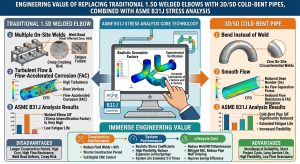
二、 CCUS 與 SCR 系統之腐蝕機制與流體力學探討/2. Investigation of Corrosion Mechanisms and Fluid Dynamics in CCUS and SCR Systems
2.1 碳捕捉系統中的胺液應力腐蝕龜裂 (Amine SCC) 機制/2.1 Amine Stress Corrosion Cracking (Amine SCC) Mechanism in Carbon Capture Systems
碳捕捉系統主要利用單乙醇胺(Monoethanolamine, MEA)、二乙醇胺(Diethanolamine, DEA)或甲基二乙醇胺(Methyldiethanolamine, MDEA)等弱鹼性溶劑,在吸收塔內與煙氣中的二氧化碳發生化學吸收反應,並在再生塔(Regenerator / Stripper)中透過高溫加熱釋放高純度二氧化碳。在此熱力學循環與流體傳輸製程中,碳鋼管線極易受到胺液應力腐蝕龜裂(Amine SCC)的威脅2。胺液裂解本質上屬於鹼性應力腐蝕龜裂的一種特殊形式,其發生的三個關鍵要素為:高濃度的胺液環境、特定的溫度區間,以及金屬晶格內部存在足以驅動裂紋擴展的高張應力2。 Carbon capture systems primarily utilize weak alkaline solvents such as Monoethanolamine (MEA), Diethanolamine (DEA), or Methyldiethanolamine (MDEA) to undergo chemical absorption reactions with carbon dioxide in flue gas within an absorber, subsequently releasing high-purity carbon dioxide through high-temperature heating in a regenerator/stripper. During this thermodynamic cycle and fluid transmission process, carbon steel piping is highly susceptible to Amine Stress Corrosion Cracking (Amine SCC)2. Amine cracking is essentially a specific form of alkaline stress corrosion cracking, requiring three critical elements to occur: a high-concentration amine environment, a specific temperature range, and high tensile stresses within the metal lattice sufficient to drive crack propagation 2.
在傳統的 1.5D 銲接彎頭中,管件與直管對銲(Butt Weld)處的熱影響區(HAZ)會因銲接過程的劇烈熱循環,產生微觀組織的變異,並伴隨極高的殘餘張應力3。根據美國腐蝕工程師協會標準 NACE MR0175(亦發行為 ISO 15156)以及美國石油協會 API RP 945 的規範,為了降低在硫化氫(H2S)酸性環境與鹼性胺液環境下的環境輔助龜裂風險,碳鋼銲縫與熱影響區的硬度必須被嚴格控制在 22 HRC(或 235 HV)以下,並且強烈建議進行銲後熱處理(Post-Weld Heat Treatment, PWHT)以釋放殘餘應力並回火軟化脆性組織9。 In traditional 1.5D welded elbows, the Heat-Affected Zone (HAZ) at the butt weld between the fitting and the straight pipe undergoes microstructural alterations due to the severe thermal cycles of the welding process, accompanied by extremely high residual tensile stresses 3. According to the National Association of Corrosion Engineers standard NACE MR0175 (also published as ISO 15156) and the American Petroleum Institute’s API RP 945 guidelines, to mitigate the risk of environmentally assisted cracking in acidic hydrogen sulfide (H2S) and alkaline amine environments, the hardness of carbon steel welds and HAZs must be strictly controlled below 22 HRC (or 235 HV)10. It is strongly recommended to perform Post-Weld Heat Treatment (PWHT) to relieve residual stresses and temper brittle structures 9.
然而,現場管線施作的 PWHT 作業不僅耗時且成本高昂。更為致命的是,若熱處理的恆溫區間、升降溫速率或保溫時間控制不當,不僅無法完全消除潛在的殘餘應力,甚至可能引發蠕變龜裂或降低材料的抗拉強度2。此外,銲縫的幾何不連續性(如銲冠與銲趾)本身即為應力集中點,這導致初始微裂紋通常沿著熱影響區平行於銲道發展,並在管內壁起始後迅速向外壁穿透,形成沿晶應力腐蝕龜裂(Intergranular stress corrosion cracking, IGSCC)2。多起失效案例研究顯示,即使是實施過 PWHT 的管線,在承受貧胺液(Lean amine)或半貧胺液(Semi-lean amine)系統的熱應力波動下,仍可能因法蘭墊片區域的高局部應力與甲酸鹽(Formate)等雜質的高濃度累積,引發迅速的管壁穿透與洩漏3。 However, on-site PWHT operations for piping are not only time-consuming but also costly. More critically, if the holding temperature range, heating/cooling rates, or soaking time are improperly controlled, it may fail to fully relieve potential residual stresses and could even induce creep cracking or diminish the material’s tensile strength 2. Furthermore, the geometric discontinuity of the weld itself (such as the weld crown and toe) acts as a stress concentration point. This typically causes initial micro-cracks to develop parallel to the weld seam along the HAZ, initiating at the inner pipe wall and rapidly penetrating outward to form Intergranular Stress Corrosion Cracking (IGSCC) 2. Multiple failure case studies have shown that even in piping subjected to PWHT, the thermal stress fluctuations in lean or semi-lean amine systems can still trigger rapid wall penetration and leakage due to high local stresses at flange gasket areas and the high accumulation of impurities like formats 3.
2.2 脫硝系統 (SCR) 中的硫酸氫銨沉積與流動加速沖刷腐蝕
2.2 Ammonium Bisulfate Deposition and Flow-Accelerated Erosion-Corrosion in SCR Systems
在 SCR 脫硝系統中,氨氣(NH3)或尿素溶液被精確注入高溫煙氣中,在催化劑的作用下將氮氧化物(NOx)還原為氮氣與水。然而,煙氣中不可避免殘留的未反應氨氣(Ammonia slip)會與燃料燃燒產生的三氧化硫(SO3)及氣態硫酸(H2SO4)發生結合反應。當操作溫度下降至特定的露點區間(通常位於空氣預熱器或靜電集塵器前端),會生成極具黏性、吸濕性且具高度腐蝕性的硫酸氫銨(Ammonium Bisulfate, ABS)1。 In SCR denitrification systems, ammonia (NH3) or urea solution is precisely injected into high-temperature flue gas, reducing nitrogen oxides (NOx) into nitrogen and water under the action of a catalyst. However, inevitable unreacted ammonia slip in the flue gas will react with sulfur trioxide (SO3) and gaseous sulfuric acid (H2SO4) generated from fuel combustion. When the operating temperature drops to a specific dew point range (typically upstream of the air preheater or electrostatic precipitator), highly viscous, hygroscopic, and highly corrosive Ammonium Bisulfate (ABS) is formed 1.
當含有 ABS 沉積物、固體飛灰微粒與高濃度氨水液滴的氣液固多相流,以極高流速經過管線方向劇烈改變的 1.5D 銲接彎頭時,流體動力學特徵會發生急遽惡化。流體在短曲率半徑的內弧處會產生嚴重的流動分離(Flow separation),並在管腔截面形成迪恩渦流(Dean vortices)等二次流(Secondary flows)現象。這會導致高密度的液滴與懸浮微粒無法跟隨流體流線,而是以接近 90 度的極大撞擊角(Impingement angle)直接撞擊彎頭的背弧(Extrados),引發災難性的沖刷腐蝕(Erosion-Corrosion)與流動加速腐蝕(Flow-Accelerated Corrosion, FAC)4。 When a gas-liquid-solid multiphase flow containing ABS deposits, solid fly ash particulates, and high-concentration ammonia droplets passes through a 1.5D welded elbow—where the piping direction changes abruptly—at extremely high velocities, fluid dynamic characteristics deteriorate sharply. Severe flow separation occurs at the intrados due to the short radius of curvature, forming secondary flows such as Dean vortices in the pipe cross-section. This prevents high-density droplets and suspended particulates from following the fluid streamlines, causing them to directly strike the extrados of the elbow at extreme impingement angles approaching 90 degrees. This triggers catastrophic Erosion-Corrosion and Flow-Accelerated Corrosion (FAC) 4.
實證流體力學計算與損壞分析表明,彎頭的曲率半徑比對局部壓力降、流速梯度與沖刷磨耗速率有決定性的影響。將半徑比從 1.5 提升至 3.0 或 5.0,可大幅平滑化邊界層流場分佈,將微粒的撞擊角從垂直撞擊轉變為極小角度的掠過摩擦,從而將局部流體撞擊的動能耗散。這不僅減少了壁面壓力降,更能徹底消除二次流造成的壁厚局部掏空現象,進而顯著延長脫硝與集塵管件的服役壽命4。 Empirical fluid dynamic calculations and damage analyses indicate that the bend radius ratio exerts a decisive influence on the local pressure drop, velocity gradient, and erosion wear rate. Increasing the radius ratio from 1.5 to 3.0 or 5.0 significantly smooths the boundary layer flow distribution, altering the particulate impingement angle from a perpendicular strike to a very shallow glancing friction, thereby dissipating the kinetic energy of local fluid impacts. This not only reduces wall pressure drop but also completely eliminates localized wall thinning caused by secondary flows, consequently significantly extending the service life of SCR and dust collection piping components 4.
| 流體力學與腐蝕特徵 / Fluid Dynamics & Corrosion Features | 1.5D 銲接彎頭 / 1.5D Welded Elbows (ASME B16.9) | 3D/5D 冷作彎管 / 3D/5D CNC Cold Bends | 改善效益分析 / Improvement Analysis |
| 流動分離現象 / Flow Separation | 極為嚴重,內弧伴隨負壓區與渦流 / Severe, negative pressure & vortices at intrados | 流線平穩附著,無明顯分離區 / Smooth streamlines, no significant separation | 消除震動源與壓力脈動 / Eliminates vibration sources and pressure pulsation |
| 二次流與湍流強度 / Secondary Flow & Turbulence | 迪恩渦流強烈,徑向流速不均 / Strong Dean vortices, uneven radial velocity | 渦流強度衰減,流速分佈均勻 / Weakened vortices, uniform velocity distribution | 降低管壁剪應力 / Reduces Wall Shear Stress |
| 顆粒撞擊角 / Particle Impingement Angle | 高撞擊角,動能轉化為破壞功 / High angle, kinetic energy causes damage | 低撞擊角,顆粒隨流線滑過壁面 / Low angle, particles glide past the wall | 延長管壁壽命,抗流動加速腐蝕 / Extends wall life, resists FAC |
| ASCC 易發位置 / ASCC Susceptible Locations | 環向對銲縫與熱影響區 (HAZ) / Circumferential butt welds and HAZ | 無銲縫,無熱影響區 / Seamless, no HAZ | 根本消除冶金缺陷引發的應力腐蝕 / Fundamentally eliminates SCC caused by metallurgical defects |
| 局部系統壓力降 / Local System Pressure Drop | 高,需較大泵浦揚程 / High, requires larger pump head | 顯著降低,流阻係數微小 / Significantly reduced, minimal flow resistance | 降低傳輸耗能,提升熱效率 / Reduces transmission energy consumption, boosts thermal efficiency |
三、 ASME B31.3 壓力管線厚度設計與冷彎冶金限制/3. ASME B31.3 Pressure Piping Thickness Design and Cold Bending Metallurgical Limitations
為徹底解決上述熱影響區腐蝕與流體沖刷的問題,採用數控冷作彎管(CNC Cold Bending)一體成型製程成為現代高能管線設計的最佳實踐。冷作彎管消除了管線方向改變處的環向銲縫,使得直管與彎管段之間的過渡呈現完美的幾何與冶金連續性。然而,管壁在承受高壓流體與冷作塑性變形時的厚度變化與應力重分配,必須依據 ASME B31.3 進行嚴謹的理論計算。To thoroughly resolve the aforementioned HAZ corrosion and fluid erosion issues, the adoption of one-piece CNC Cold Bending processes has become the best practice in modern high-energy piping design. Cold bending eliminates circumferential welds at points of direction change, creating perfect geometric and metallurgical continuity in the transition between straight pipe and curved segments. However, the wall thickness variations and stress redistribution when the pipe wall is subjected to high-pressure fluids and cold plastic deformation must be rigorously calculated in accordance with ASME B31.3.
3.1 直管壁厚設計與溫度相依之 Y 係數 (Y-Factor)/3.1 Straight Pipe Wall Thickness Design and Temperature-Dependent Y-Factor
在計算彎管厚度之前,必須先確立連接直管的壓力設計厚度。ASME B31.3 規範第 304.1.2 節提供了一般內部壓力下直管厚度的計算公式(即修正式 Barlow 方程式)19: Before calculating the bend thickness, the pressure design thickness of the connecting straight pipe must first be established. Section 304.1.2 of the ASME B31.3 code provides the calculation formula for straight pipe thickness under general internal pressure (i.e., the modified Barlow’s equation)19:
tstraight=(P⋅Do)/2(S⋅E⋅W+P⋅Y)
式中,P 為內部設計壓力,Do 為管外徑,S 為材料在設計溫度下的許用應力,E 為銲縫品質係數,W 為銲縫強度折減係數,而 Y 為無因次係數(Y-factor)19。 Where P is the internal design pressure, Do is the pipe outside diameter, S is the material allowable stress at the design temperature, E is the quality factor, W is the weld joint strength reduction factor, and Y is the dimensionless Y-factor coefficient 19.
引入 Y 係數的核心物理意義在於補償厚壁圓筒內部應力分佈的不均勻性。根據拉梅方程式(Lame’s Equation),管壁所承受的環向應力(Hoop stress)並非均勻分佈,內壁的環向應力永遠大於外壁。如果僅基於最大內部環向應力來計算壁厚,將會導致管壁設計過度保守、材料浪費且徒增管線重量與剛性20。Y 係數允許計算中反映出材料在局部應力達到降伏點時的塑性應力重分配現象,從而減少所需的計算壁厚20。 The core physical significance of introducing the Y factor lies in compensating for the uneven stress distribution inside thick-walled cylinders. According to Lame’s Equation, the hoop stress sustained by the pipe wall is not uniformly distributed; the hoop stress at the inner wall is always greater than at the outer wall. If wall thickness were calculated solely based on the maximum internal hoop stress, it would lead to overly conservative designs, material waste, and an unnecessary increase in piping weight and stiffness20. The Y factor allows the calculation to reflect the plastic stress redistribution phenomenon when localized stresses reach the yield point, thereby reducing the required calculated wall thickness 20.
值得注意的是,根據 ASME B31.3 的規定,Y 係數是高度溫度相依的。對於肥粒鐵系碳鋼,在常溫至中溫區間 Y 值通常為 0.4;但當溫度升高至蠕變範圍(例如超過480°C)時,Y 值會遞增至 0.5 或 0.7 20。這種現象的物理學解釋在於,高溫下金屬材料變得更為柔軟,局部降伏發生得更早,材料能夠更有效地將內壁的高峰應力向外壁傳遞與平均化,因此規範允許給予更大的厚度減免係數。反之,對於鑄鐵等脆性材料,因其缺乏吸收與重分配局部應力的塑性變形能力,規範將 Y 係數嚴格設定為零,不允許任何折減20。 It is worth noting that, according to ASME B31.3 regulations, the Y factor is highly temperature-dependent. For ferritic carbon steels, the Y value is typically 0.4 in the ambient to intermediate temperature range; however, when the temperature rises into the creep range (e.g., above 480°C), the Y value increases to 0.5 or 0.7 20. The physical explanation for this phenomenon is that metallic materials become softer at high temperatures, localized yielding occurs earlier, and the material can more effectively transfer and average out peak stresses from the inner wall to the outer wall. Thus, the code allows for a greater thickness reduction coefficient. Conversely, for brittle materials like cast iron, due to their lack of plastic deformation capacity to absorb and redistribute localized stresses, the code strictly sets the Y factor to zero, disallowing any reduction 20.
3.2 彎管外弧與內弧之應力重分配與 I 係數 (I-Factor)/3.2 Stress Redistribution and I-Factor at the Extrados and Intrados of Bends
在數控冷彎成型過程中,金屬材料發生劇烈的塑性變形。彎管的外弧(Extrados)因受到拉伸應變而產生物理上的壁厚減薄(Wall thinning);相反地,內弧(Intrados)因受到壓縮應變而產生壁厚增厚(Wall thickening)19。 During the CNC cold bending process, the metallic material undergoes severe plastic deformation. The extrados of the bend experiences tensile strain, resulting in physical wall thinning; conversely, the intrados is subjected to compressive strain, causing wall thickening 19.
然而,從壓力容器的應力分析角度來看,內部流體壓力所產生的環向應力在環形體(Torus)幾何中與直管截然不同。由於內弧的幾何特徵,相同的內部壓力作用在較短的內側圓周上,導致內弧所承受的真實環向應力大於直管與外弧22。這產生了一個反直覺的工程設計現象:雖然加工使得外弧變薄,但真正需要更厚管壁來抵抗內部壓力的卻是內弧。 However, from the perspective of pressure vessel stress analysis, the hoop stress generated by internal fluid pressure in a torus geometry is entirely different from that in a straight pipe. Due to the geometric characteristics of the intrados, the same internal pressure acts over a shorter inner circumference, causing the true hoop stress sustained by the intrados to be greater than that of the straight pipe and the extrados 22. This results in a counter-intuitive engineering design phenomenon: although the forming process thins the extrados, it is actually the intrados that requires a thicker pipe wall to resist internal pressure.
為了精確補償這種幾何效應,ASME B31.3 規範第 304.2.1 節引入了應力修正係數(I-factor),分別評估彎管內弧與外弧的應力強化程度19。其解析公式如下: To accurately compensate for this geometric effect, ASME B31.3 Section 304.2.1 introduces the stress correction factor (I-factor) to separately evaluate the degree of stress intensification at the intrados and extrados of the bend 19. Its analytical formulas are as follows:
於內弧處(Intrados):Iintrados=[4(R/Do)-1]/[4(R/Do)-2]
於外弧處(Extrados):Iextrados=[4(R/Do)+1]/[4(R/Do)+2]
此處,R 為彎曲中心線半徑(Bend radius to centerline)。計算所得的 I 係數將作為分母直接作用於許用應力 S,修正原有的厚度方程式22: Here, R is the bend radius to the centerline. The calculated I factor acts as a denominator directly affecting the allowable stress S, thereby modifying the original thickness equation 22:
tbend=(P⋅Do)/2((S⋅E⋅W)/I+P⋅Y) +A
由於 Iintrados 恆大於 1.0,它會折減材料的有效許用應力,進而要求內弧具備比直管更厚的最小計算壁厚;而 Iextrados 恆小於 1.0,則在理論上允許外弧承受較薄的壁厚要求19。 Since Iintrados is always greater than 1.0, it reduces the material’s effective allowable stress, thereby demanding a thicker minimum calculated wall thickness for the intrados compared to a straight pipe. Conversely, Iextrados is always less than 1.0, theoretically allowing the extrados to have a thinner wall thickness requirement 19.
相較於 1.5D 彎頭,3D 與 5D 冷作彎管擁有龐大的彎曲半徑與外徑比例。以一標準管線為例:Compared to 1.5D elbows, 3D and 5D cold bends possess a massive ratio of bend radius to outside diameter. Using a standard pipe as an example:
- 若採用1.5D 彎頭:內弧應力修正為 1.25,這意味著內弧承受了 25% 的額外應力集中,需大幅增加管壁厚度。If a 1.5D elbow is used: the intrados stress correction is 1.25, meaning the intrados endures an additional 25% stress concentration, requiring a substantial increase in wall thickness.
- 若採用 5D 彎管:內弧應力修正約為1.055,這顯示 5D 彎管的應力狀態幾乎等同於理想直管,僅有 5.5% 的應力偏差。If a 5D bend is used: the intrados stress correction is approximately 1.055, indicating that the stress state of a 5D bend is nearly equivalent to an ideal straight pipe, with only a 5.5% stress deviation.
這項理論計算證實,採用大曲率半徑的 3D/5D 彎管不僅優化了流體動力學,更在承壓能力上遠優於 1.5D 彎頭,使其在面對碳捕捉與脫硝系統的極端壓力波動時,具備更高的結構安全餘裕。
These theoretical calculations confirm that the adoption of large-radius 3D/5D bends not only optimizes fluid dynamics but also offers far superior pressure-bearing capabilities compared to 1.5D elbows, equipping them with a higher structural safety margin against extreme pressure fluctuations in CCUS and SCR systems.
| 幾何參數與 I 係數比較 / Geometric Parameters & I-Factor Comparison | 1.5D 彎頭 / 1.5D Elbow | 3D 冷作彎管 / 3D Cold Bend | 5D 冷作彎管 / 5D Cold Bend | 物理意義與影響 / Physical Significance & Impact |
| 半徑與外徑比 / Radius-to-OD Ratio (R/Do) | 1.5 | 3.0 | 5.0 | 決定環形體應力分佈的核心變數 / Core variable determining torus stress distribution |
| 內弧應力修正 / Intrados Stress Correction (Iintrados) | 1.250 | 1.100 | 1.055 | 數值越接近 1.0,應力集中越輕微 / Values closer to 1.0 indicate milder stress concentration |
| 外弧應力修正 / Extrados Stress Correction (Iextrados) | 0.875 | 0.928 | 0.954 | 外弧容許的厚度下限 / Permissible lower limit for extrados thickness |
| 母材壁厚需求 / Mother Pipe Wall Requirement | 需特殊加厚鍛造 / Requires special forged thickness | 增加一個排程 / Increase one schedule | 微幅增加或維持原排程 / Slight increase or maintain schedule | 3D/5D 降低特殊鍛件與材料成本 / 3D/5D reduces special forging and material costs |
3.3 塑性應變與彎後熱處理 (PBHT) 之冶金控制/3.3 Metallurgical Control of Plastic Strain and Post-Bend Heat Treatment (PBHT)
儘管 3D/5D 冷彎工法免除了易肇生 ASCC 的銲縫,但室溫下的冷作加工會引發材料晶格內部的差排(Dislocations)大量增殖與交錯,導致嚴重的加工硬化(Strain hardening)。巨觀上,這表現為材料的降伏強度顯著提升,但延展性與衝擊韌性急遽下降。更重要的是,冷作塑性變形會在管壁內部留下極大的微觀殘餘應力網絡,若暴露於胺液或高濃度氯離子環境中,將極易誘發環境輔助龜裂2。 Although the 3D/5D cold bending method eliminates welds prone to ASCC, cold working at room temperature induces a massive multiplication and entanglement of dislocations within the material’s lattice, leading to severe strain hardening. Macroscopically, this manifests as a significant increase in yield strength, but a drastic drop in ductility and impact toughness. More importantly, cold plastic deformation leaves a vast network of micro-residual stresses within the pipe wall, which, if exposed to amine solutions or high-concentration chloride environments, will highly likely induce environmentally assisted cracking 2.
依據國際材料規範,當碳鋼管線冷彎變形的纖維塑性應變率(Strain percentage)超過 5% 極限值時,必須進行彎後熱處理(Post-Bend Heat Treatment, PBHT)12。對於胺液系統,API RP 945 明確建議限制任何高應力與冷作區域的硬度12。 According to international material specifications, when the fiber plastic strain percentage of carbon steel piping subjected to cold bending deformation exceeds the 5% limit, Post-Bend Heat Treatment (PBHT) must be performed12. For amine systems, API RP 945 explicitly recommends limiting the hardness in any high-stress and cold-worked regions 12.
透過在嚴格控制的溫度區間內(例如將碳鋼加熱至 600°C 至 650°C 進行應力消除退火,或視鋼種特性加熱至 Ac3 轉變溫度以上進行正常化處理)執行 PBHT,能夠提供足夠的熱激活能,促使變形晶粒內部發生差排回復(Recovery)、甚至引發再結晶(Recrystallization)形成無應變的新晶粒23。此一熱處理程序能徹底消除冷作殘餘應力網絡,將外弧與內弧的硬度重新控制於 NACE MR0175 所規定的 22 HRC 之下10。經過完善 PBHT 程序的 3D/5D 彎管,不僅擁有一體成型的平滑幾何,更恢復了等同於母材的優異冶金韌性,完美抵禦了胺液應力腐蝕龜裂的威脅。 By performing PBHT within a strictly controlled temperature range (e.g., heating carbon steel to 600°C-650°C for stress-relief annealing, or heating above the Ac3 transformation temperature for normalizing, depending on the steel grade), sufficient thermal activation energy is provided to induce dislocation recovery within deformed grains, or even trigger recrystallization to form new, strain-free grains 23. This heat treatment procedure can completely eliminate the cold-worked residual stress network, re-controlling the hardness at both the extrados and intrados to below the 22 HRC limit stipulated by NACE MR0175 10. 3D/5D bends processed through a comprehensive PBHT procedure not only possess a seamlessly formed smooth geometry but also restore excellent metallurgical toughness equivalent to the mother pipe, perfectly resisting the threat of Amine SCC.
四、 ASME B31J 應力解析之理論演進與力學特徵/4. Theoretical Evolution and Mechanical Characteristics of ASME B31J Stress Analysis
管線應力分析(Piping Stress Analysis)的核心目的在於準確評估複雜三維管線系統在熱膨脹、設備位移、自重、內部壓力以及地震與水錘等動態負載下的位移響應與應力極值。長久以來,全球工程界廣泛遵循的 ASME B31.1(動力管線)與 B31.3(製程管線)規範,高度仰賴 1940 至 1950 年代由 A.R.C. Markl 針對 4 吋標準厚度碳鋼管所進行的懸臂彎曲疲勞測試數據,並以此作為應力強度因子(SIF, i)與撓性係數(Flexibility Factor, k)的計算基石(即 ASME B31.3 舊版附錄 D)5。 The core objective of Piping Stress Analysis is to accurately evaluate the displacement response and maximum stress values of complex three-dimensional piping systems under dynamic loads such as thermal expansion, equipment displacement, dead weight, internal pressure, earthquakes, and water hammer. For a long time, the global engineering community broadly followed the ASME B31.1 (Power Piping) and B31.3 (Process Piping) codes, which relied heavily on cantilever bending fatigue test data conducted by A.R.C. Markl on 4-inch standard thickness carbon steel pipes in the 1940s and 1950s. This data served as the foundational basis for calculating Stress Intensification Factors (SIF, i) and Flexibility Factors (k)—formerly known as ASME B31.3 Appendix D 5.
4.1 傳統 Markl 理論與附錄 D 之結構性侷限/4.1 Structural Limitations of Traditional Markl Theory and Appendix D
Markl 疲勞方程式的假設前提在面對現代高溫高壓、大口徑、薄壁化(高徑厚比)且材質多樣的發電廠與石化管線時,暴露出極大的保守性與理論盲點8。 When confronting modern power plant and petrochemical piping characterized by high temperatures, high pressures, large diameters, thin walls (high diameter-to-thickness ratio), and diverse materials, the assumptions of Markl’s fatigue equations expose profound conservativeness and theoretical blind spots 8.
首先,舊版附錄 D 對於彎頭與三通管(Tees)強行賦予單一的 SIF 數值,並未區分面內(In-Plane)與面外(Out-of-Plane)彎矩的作用差異。實際上,當彎矩施加於管件時,由於元件幾何的非對稱性塑性變形(例如彎管截面的橢圓化現象 Ovalization),面內彎矩(使彎管兩端靠攏或張開)與面外彎矩(使一端移出其原本所在的平面)會產生截然不同位置與幅度的應力集中5。其次,舊版規範忽略了扭轉力矩(Torsional moment)對剪應力集中的貢獻,一律預設扭轉 SIF 為 it =1.0 5。再者,附錄 D 採用封閉式解(Closed-form solutions),容易導致工程師產生指派錯誤。例如,將彎頭的附錄 D 經驗公式直接套用於銲接三通管,會導致面外應力強度因子被嚴重低估 20%(因 0.9/0.75=1.2),形成潛在的斷裂風險8。 Firstly, legacy Appendix D forced a single SIF value for elbows and tees, failing to differentiate between the effects of In-Plane and Out-of-Plane bending moments. In reality, when bending moments are applied to piping components, the asymmetrical plastic deformation of the component geometry (such as the ovalization of the bend cross-section) causes in-plane moments (which push the bend ends together or apart) and out-of-plane moments (which move one end out of its original plane) to generate stress concentrations of entirely different locations and magnitudes 5. Secondly, the legacy code ignored the contribution of torsional moments to shear stress concentration, uniformly presetting the torsional SIF to it =1.0 5. Furthermore, Appendix D utilized closed-form solutions, which easily led to assignment mistakes by engineers. For example, directly applying the Appendix D empirical formula for an elbow to a welded tee results in the out-of-plane SIF being severely underestimated by exactly 20% (since 0.9/0.75=1.2), creating a potential fracture risk 8.
4.2 ASME B31J 之數值實驗矩陣與多維應力重構/4.2 Numerical Experimental Matrix and Multi-Dimensional Stress Reconstruction in ASME B31J
為徹底解決上述解析缺陷,美國機械工程師學會發布了革命性的 ASME B31J 標準。此規範匯集了數十萬小時的先進實體殼單元與實體磚單元(Shell and Brick models)有限元素分析(FEA),並輔以嚴謹的實驗室測試數據進行驗證。它為各式管件建立了更真實的應力與撓性指標,並已成為 2020 年版之後 ASME B31.1 與 B31.3 的強制預設演算法5。 To completely resolve these analytical defects, the American Society of Mechanical Engineers released the revolutionary ASME B31J standard. This code aggregates hundreds of thousands of hours of advanced solid shell and brick model Finite Element Analysis (FEA), supplemented and validated by rigorous laboratory test data. It establishes more realistic stress and flexibility metrics for various piping components and has become the mandatory default algorithm for ASME B31.1 and B31.3 from the 2020 editions onward 5.
ASME B31J-2023 針對彎管與彎頭,定義了核心的幾何「撓性特徵值」(Flexibility characteristic, h):ASME B31J-2023 defines the core geometric “Flexibility characteristic” (h) for bends and elbows:
h=(T⋅R1)/r22
其中,T 為管線公稱壁厚,R1 為彎曲半徑,r2 為管線平均半徑26。特徵值 h 是決定管件橢圓化難易程度的無因次參數,管壁越薄或半徑越大,管件越容易變形。 Where T is the nominal wall thickness of the pipe, R1 is the bend radius, and r2 is the mean pipe radius 26. The characteristic h is a dimensionless parameter determining how easily the component ovalizes; the thinner the wall or the larger the radius, the easier the component deforms.
基於特徵值 h,ASME B31J Table 1-1 將單一的管件彎矩作用明確拆解,建構出多維度的 SIF 張量:Based on the characteristic h, ASME B31J Table 1-1 explicitly breaks down the singular component bending moment effect, constructing a multi-dimensional SIF tensor:
- 面內應力強度因子 (ii):B31J 保留並修正了9/h2/3 的基礎關係式。In-Plane SIF (ii): B31J retains and modifies the foundational relation of 0.9/h2/3.
- 面外應力強度因子 (io):針對面外彎矩,定義為 75/h2/3。Out-of-Plane SIF (io): For out-of-plane moments, it is defined as 0.75/h2/3.
- 扭轉應力強度因子 (it):B31J 正式將扭轉 SIF 納入位移應力範圍計算,精確反映三維空間管線佈置中的扭轉剪力集中現象26。 Torsional SIF (it): B31J officially integrates the torsional SIF into the displacement stress range calculations, accurately reflecting torsional shear stress concentration phenomena in 3D spatial piping layouts 26.
在撓性模型方面,撓性係數(k-factor)定義為:Regarding the flexibility model, the flexibility factor (k-factor) is defined as:
k=1.65/h
k 係數直接進入管線應力軟體(如 CAESAR II, AutoPIPE)的系統總體剛度矩陣中,用以縮放元件的旋轉剛度,改變全系統的彎矩分佈31。特別值得一提的是,當高壓流體通過大口徑薄壁彎管時,巨大的內部流體壓力會像氣球一樣抵抗彎管截面的橢圓化變形,這種「壓力剛化效應」(Pressure-stiffening correction)會導致 k 值下降(剛性回升),同時 SIF 也會相應減小。ASME B31J 全面考量並自動化了這些物理耦合效應8。The k factor feeds directly into the global stiffness matrix of piping stress software (e.g., CAESAR II, AutoPIPE), scaling the rotational stiffness of the component and altering the bending moment distribution across the entire system 31. Particularly noteworthy is that when high-pressure fluid passes through large-diameter thin-walled bends, the massive internal fluid pressure acts like a balloon to resist the ovalization of the bend cross-section. This “Pressure-stiffening correction” causes the k value to drop (stiffness recovers), while the SIF correspondingly decreases. ASME B31J comprehensively accounts for and automates these physical coupling effects 8.
4.3 高周波疲勞評估與 3D/5D 彎管的壽命躍升/4.3 High Cycle Fatigue Assessment and the Lifespan Leap of 3D/5D Bends
在疲勞壽命的評估上,ASME B31.3 在 Appendix W 引入了高周波疲勞(High Cycle Fatigue)評估程序,該程序借鑒了 ASME VIII-2 壓力容器規範的疲勞曲線。學術界對此進行的批判性分析指出,傳統 Markl 理論基礎的 SIF 實際上是基於「帶有對銲銲縫的管件」(Welded joints)所推導出的,這意味著其疲勞曲線天生內建了銲縫處微觀缺陷與應力集中的折減係數6。 For fatigue life assessment, ASME B31.3 Appendix W introduced a High Cycle Fatigue evaluation procedure, drawing on fatigue curves from the ASME VIII-2 pressure vessel code. Critical academic analysis points out that the SIF based on traditional Markl theory is actually derived from “welded joints,” meaning its fatigue curves inherently possess built-in reduction coefficients for micro-defects and stress concentrations at the welds 6.
當使用 3D/5D 數控冷作彎管取代銲接彎頭時,彎曲段內完全沒有任何環向銲縫。這在理論與規範實務上意味著,工程師可以將該元件的疲勞評估基準,從嚴苛的「銲接接頭疲勞設計曲線」轉換至容許應力範圍高出極多的「平滑試片疲勞設計曲線」(Smooth bar design fatigue curves)6。平滑試片曲線不僅在低周波與高周波區域容許更大的等效應力幅值,更消除了銲縫所必需的非線性應力乘數與結構應力轉換懲罰6。這種規範定義上的轉移,使得採用 3D/5D 彎管的管線系統,其理論預測疲勞壽命可輕易達到傳統 1.5D 銲接彎頭的數倍之多。 When 3D/5D CNC cold bends replace welded elbows, there are absolutely no circumferential welds within the curved segment. In both theory and code practice, this means engineers can shift the component’s fatigue assessment baseline from the stringent “welded joint design fatigue curves” to the “smooth bar design fatigue curves,” which allow for a vastly higher stress range 6. Smooth bar curves not only permit larger equivalent stress amplitudes in both low-cycle and high-cycle regions, but they also eliminate the non-linear stress multipliers and structural stress conversion penalties necessitated by welds6. This regulatory baseline shift allows piping systems adopting 3D/5D bends to easily achieve a theoretically predicted fatigue life several times that of traditional 1.5D welded elbows.
五、 3D/5D 冷作彎管與 1.5D 銲接彎頭之系統級綜合比較分析/5. System-Level Comprehensive Comparative Analysis of 3D/5D Cold Bends and 1.5D Welded Elbows
5.1 SIF 之非線性衰減效應與力學優勢/5.1 Non-linear Attenuation Effect of SIF and Mechanical Advantages
由特徵值公式 h=(T⋅R1)/r22 可知,h 值與彎曲中心線半徑 R1呈現完全正比。對於相同外徑與壁厚的管線而言:From the characteristic formula h=(T⋅R1)/r22, it is evident that the h value is directly proportional to the bend centerline radius R1. For piping with the same outside diameter and wall thickness:
- 傳統銲接彎頭的R1=1.5*Do。Traditional welded elbows have R1=1.5*Do .
- 冷作彎管的 R1=3.0*Do 甚至R1=5.0*Do。Cold bends have R1=3.0*Do or even R1=5.0*Do .
當 R1 增加 2 倍(至 3D)或 3.33 倍(至 5D)時,特徵值 h 將等比例放大 2 倍或 3.33 倍。由於面內 SIF 與面外 SIF 均與 h2/3 呈現反比關係(i∝h-2/3),這意味著應力強度因子會隨著彎曲半徑的擴大而呈現非線性的顯著下降。例如,從 1.5D 提升至 5D 時,SIF 將下降至原數值的約 0.45 倍,降幅高達 55%。這代表 5D 彎管的幾何構造將幾乎不產生額外的應力集中,其應力表現逼近完美的理論直管26。 When R1 increases by a factor of 2 (to 3D) or 3.33 (to 5D), the characteristic h scales proportionally by 2 or 3.33 times. Since both in-plane and out-of-plane SIFs are inversely proportional to h2/3 (i∝h-2/3), the SIF will exhibit a significant non-linear decline as the bend radius expands. For instance, upgrading from 1.5D to 5D reduces the SIF to approximately 0.45 times its original value, a massive drop of 55%. This indicates that the 5D bend’s geometric structure generates almost no additional stress concentration, with a stress performance approaching that of a theoretically perfect straight pipe 26.
5.2 系統熱膨脹位移吸收與設備負載最小化/5.2 System Thermal Expansion Displacement Absorption and Equipment Load Minimization
在 CCUS 的胺液再生塔管線與 SCR 的高溫煙氣管線中,操作溫度經常高達數百攝氏度。根據熱脹冷縮物理原理,龐大的熱膨脹位移必須被管線系統自身的幾何形狀與撓性所吸收,否則將產生足以破壞支架與設備的巨大熱應力5。 In CCUS amine regenerator piping and SCR high-temperature flue gas piping, operating temperatures frequently reach hundreds of degrees Celsius. According to the physical principles of thermal expansion and contraction, massive thermal expansion displacement must be absorbed by the piping system’s own geometry and flexibility; otherwise, tremendous thermal stresses capable of destroying supports and equipment will be generated 5.
從局部元件的微觀角度來看,隨著 h 值增加,單位的撓性係數k=1.65/h呈現下降趨勢,這意味著每單位弧長的剛性變強,變形更加困難32。然而,從宏觀的全系統剛度矩陣來看,由於 3D/5D 彎管的實體弧長遠大於 1.5D 彎頭,系統整體的幾何柔性反而大幅增加。這種「局部剛化但整體變長」的幾何物理效應,賦予了整個管線系統更加卓越的應變能吸收(Strain energy absorption)能力5。 From a micro-perspective of local components, as the h value increases, the unit flexibility factor k=1.65/h trends downward, meaning rigidity increases per unit arc length, making deformation more difficult 32. However, from a macro-perspective of the global stiffness matrix, because the physical arc length of 3D/5D bends is much greater than that of 1.5D elbows, the system’s overall geometric flexibility actually increases significantly. This “locally stiffened but globally lengthened” geometric physical effect endows the entire piping system with superior strain energy absorption capabilities 5.
導入大半徑冷作彎管後,由於系統吸收位移的能力提升且 SIF 大幅降低,真實的系統應力分佈被精確計算,多數膨脹環(Expansion Loops)可被簡化或刪除,並大幅降低連接設備的噴嘴反力與力矩(Nozzle Loads)。這不僅極大化地節省了發電廠的立體空間配置,更省下了龐大的鋼結構支撐成本與後續的維護費用5。 By incorporating large-radius cold bends, as the system’s displacement absorption capacity improves and SIFs are significantly reduced, the true system stress distribution is calculated precisely. Most Expansion Loops can be simplified or eliminated, and nozzle reaction forces and moments on connected equipment are vastly reduced. This not only maximizes the conservation of 3D spatial layout in power plants but also saves on massive steel structure support costs and subsequent maintenance expenses 5.
5.3 消除持續應力乘數之過度保守估計/5.3 Elimination of Overly Conservative Estimates for Sustained Stress Multipliers
管線除了承受熱膨脹的位移應力外,亦須承受如自重、內部壓力等「持續應力」(Sustained Stress)。過去,設計規範將疲勞測試得出的滿額 i 值直接套用於持續應力計算,導致厚度或跨距設計過於保守。In addition to displacement stress from thermal expansion, piping must also withstand “Sustained Stress,” such as dead weight and internal pressure. In the past, design codes applied the full i values derived from fatigue tests directly to sustained stress calculations, leading to overly conservative thickness or span designs.
ASME B31J 引入了更符合物理失效模式的乘數設計。B31J 明確指出,針對持續負載的塌陷極限狀態,其破壞機制為塑性潰乏,嚴重程度遠低於交變應力導致的疲勞極限狀態。因此,B31J 規定採用 0.75i作為應力乘數(最小值 1.0),徹底取代了過往保守設定5。因為 3D/5D 冷作彎管的基礎 i 值已經透過大半徑幾何設計被大幅壓低,這使得管線系統在面臨脫硝氨水泵啟停、安全閥排放等動態操作時,具備無與倫比的安全係數。 ASME B31J introduces a multiplier design that aligns better with physical failure modes. B31J clearly notes that the collapse limit state for sustained loads has a failure mechanism of plastic collapse, the severity of which is far lower than the fatigue limit state caused by alternating stresses. Therefore, B31J mandates the use of 0.75i as the stress multiplier (with a minimum of 1.0), thoroughly replacing past conservative settings 5. Because the baseline i values for 3D/5D cold bends are already substantially lowered through large-radius geometric design, this grants the piping system an unmatched safety factor during dynamic operations like the start/stop of SCR ammonia pumps or safety valve relief.
六、 實務工程導入與最佳化設計策略
6. Practical Engineering Implementation and Optimized Design Strategies/6.1 母材壁厚預留與採購策略 (Mother Pipe Selection Strategy)
工程師必須預先考量冷彎製程中外弧的物理壁厚減薄率,並結合前述 B31.3 的Iextrados 係數,回推所需的母材直管壁厚22。為滿足嚴苛的化學腐蝕裕度,3D 彎管的母材規格可能需比直管段高出一個排程。儘管母材成本微幅上升,但省去了特製 1.5D 鍛造管件的昂貴費用,整體經濟效益依然顯著21。 Engineers must pre-calculate the physical wall thinning rate at the extrados during the cold bending process and combine it with the aforementioned B31.3 Iextrados factor to reverse-engineer the required straight mother pipe wall thickness 22. To satisfy stringent chemical corrosion allowances, the mother pipe specification for a 3D bend might need to be one schedule higher than the straight segments. Although mother pipe costs rise slightly, avoiding the expensive costs of custom 1.5D forged fittings still provides significant overall economic benefits 21.
6.2 全面消除現場銲縫以優化關鍵要徑 (Elimination of Field Welds)
透過三維管線佈置軟體,將管線設計為由多個 3D/5D 彎管組成的大型預製管軸(Pipe Spools)。將高品質預製長管直接運至現場法蘭對接,可消滅大量高空或侷限空間現場銲接。這排除了現場射線探傷(RT)返工風險,並直接消除了現場 PWHT 時間成本,大幅縮短建廠關鍵要徑35。 By utilizing 3D piping layout software, piping is designed into large prefabricated pipe spools consisting of multiple 3D/5D bends. Shipping high-quality prefabricated long segments directly to the site for flanged connections eliminates massive amounts of high-altitude or confined-space field welding. This eliminates the rework risks of field Radiographic Testing (RT) and directly removes the time costs of field PWHT, significantly shortening the critical path of plant construction 35.
6.3 整體化熱處理與硬度檢驗管控 (Holistic PBHT Protocol)
確保整支成型後的彎管在大型均溫爐中進行恆溫退火,徹底消除冷作應變引起的差排堆積,確保碳鋼硬度百分之百符合 API RP 945 與 NACE MR0175 的嚴格要求(<22 HRC)。這是達到 CCUS 胺液系統防範 ASCC 的絕對防線10。 Ensure that the entire formed bend undergoes isothermal annealing in a large uniform-temperature furnace, completely eliminating dislocation pile-up caused by cold strain, guaranteeing that the carbon steel hardness is 100% compliant with the strict requirements of API RP 945 and NACE MR0175 (<22 HRC). This is the absolute defense line against ASCC in CCUS amine systems 10.
6.4 B31J 全域啟用與邊界條件審查 (B31J Global Activation in Software)
操作應力分析軟體時,應將 ASME B31J 設為全域分析標準7。同時必須審查邊界條件,確保管線徑厚比 D/T <= 100,並正確輸入操作內壓與材料高溫彈性模數,以觸發壓力剛化修正機制,確保受力分析精準7。 When operating stress analysis software, ASME B31J should be set as the global analysis standard 7. Simultaneously, boundary conditions must be reviewed to ensure the pipe diameter-to-thickness ratio D/T <= 100, and the operating internal pressure and high-temperature elastic modulus of the material must be correctly inputted to trigger the pressure-stiffening correction mechanism, ensuring precise stress analysis 7.
七、 產業實務擴充:營運、設計與三合一預製工法效益/7. Industrial Practice Expansion: Operational, Design, and the Benefits of the Three-in-One Prefabrication Method
7.1 業主視角:脫硝與碳捕捉管線系統之維護管理及營運決策/7.1 Owner’s Perspective: Maintenance Management and Operational Decisions for SCR and CCUS Piping Systems
在複循環發電廠全生命週期中,業主首要考量為系統可靠度與非預期停機風險最小化。強制要求採用 3D/5D 冷作彎管,業主能從物理幾何上徹底消除流體轉向處的銲縫與熱影響區,有效規避 ASCC 與 ABS 沖刷洩漏1。這不僅大幅減少大修時高風險彎頭的 RT/PAUT 檢測經費,更確保設備達到長期無失效的安全生命週期目標。 Throughout the entire lifecycle of a CCPP, the owner’s primary consideration is system reliability and minimizing forced outage risks. By mandating the use of 3D/5D cold bends, owners can physically and geometrically eliminate welds and HAZ at fluid turn points, effectively avoiding leaks caused by ASCC and ABS erosion 1. This not only substantially cuts down RT/PAUT inspection budgets for high-risk elbows during major overhauls but also guarantees the equipment achieves its long-term failure-free safe lifecycle target.
7.2 EPC 承包商設計單位視角:3D/5D 彎管之空間排列與實務考量/7.2 EPC Contractor Design Unit Perspective: Spatial Arrangement and Practical Considerations of 3D/5D Bends
導入大半徑彎管後,管線系統整體的幾何柔性與應變能吸收能力顯著提升。結合 ASME B31J 精確解析,設計單位可以取得遠低於傳統的應力強度因子,從而大幅削減施加於敏感旋轉設備的噴嘴負載5。這意味著可以簡化或刪除不必要的膨脹環,直接優化廠房管架結構(Pipe Rack)的鋼構用量與立體空間設計。 Upon integrating large-radius bends, the global geometric flexibility and strain energy absorption capacity of the piping system improve significantly. Combined with accurate ASME B31J analysis, design units obtain stress intensification factors far lower than traditional values, thereby drastically cutting nozzle loads exerted on sensitive rotating equipment 5. This means unnecessary expansion loops can be simplified or removed, directly optimizing steel usage and 3D space design in plant pipe racks.
7.3 預製廠製造視角:潁璋工程「三合一工法」之實務應用與綜合效益/7.3 Prefabrication Plant Perspective: Practical Application and Comprehensive Benefits of Ying-Chang Engineering’s “Three-in-One Method”
國內專業管線廠潁璋工程(Ying-Chang Engineering)針對發電廠需求,提出了一套「三合一冷作彎管工法」35:Domestic specialized piping manufacturer Ying-Zhang Engineering has introduced a “Three-in-One Cold Bending Method” tailored for power plant demands 35:
- 3D/5D 大半徑冷作彎管技術:運用機械連續加工取代對銲彎頭,消除應力集中與流動加速腐蝕35。3D/5D Large-Radius Cold Bending Tech: Utilizing continuous mechanical processing to replace butt-welded elbows, eliminating stress concentration and FAC 35.
- ASME B31J 應力分析驗證:在預製前將數據輸入軟體,確保管軸具最佳柔性。ASME B31J Stress Analysis Validation: Inputting data into software prior to prefabrication to guarantee optimal spool flexibility.
- 亞臨界 PBHT、去磁與數位履歷:針對 P9x 合金等鋼種,精準控制退火於 760°C,升降溫 200°C/hr 以內。同時執行嚴格的三級去磁(低於 10 Gauss),避免現場銲接「磁吹效應」,並輔以 QR Code 數位履歷透明追溯35。 此工法大幅壓縮施工期,降低 RT 浪費與鏟修風險,完美體現「品質升級與總成本降低(Cost Down)」雙重目標35。Subcritical PBHT, Degaussing, and Digital Resume: For grades like P9x alloy, annealing is precisely controlled at 760°C, with heating/cooling rates within 200°C/hr. Strict tier-three degaussing (under 10 Gauss) is executed to prevent “magnetic arc blow” during field welding, supplemented by transparent QR Code digital resume tracking 35. This method drastically compresses construction schedules, reduces RT waste and gouging repair risks, perfectly embodying the dual objectives of “quality upgrade and total cost down” 35.
八、 結論/8. Conclusion
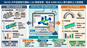
複循環發電廠(CCPP)在邁向淨零碳排放的關鍵過渡中,其脫硝(SCR)與碳捕獲(CCUS)系統承載著嚴苛的多相流體與化學腐蝕環境。本研究實證了「以 3D/5D 冷作彎管取代傳統 1.5D 銲接彎頭」結合「ASME B31J 應力解析技術」的龐大工程價值。In the critical transition towards net-zero carbon emissions, CCPP’s SCR and CCUS systems endure severe multiphase fluid and chemical corrosion environments. This study empirically demonstrates the massive engineering value of “replacing traditional 1.5D welded elbows with 3D/5D cold bends” combined with “ASME B31J stress analysis technology.”
在材料防腐與冶金層面,一體成型的冷作彎管徹底消除了銲縫與 HAZ,經 PBHT 完美阻斷了胺液應力腐蝕龜裂(ASCC);大半徑亦平滑了流場,有效抑制 ABS 沖刷腐蝕。在結構力學層面,ASME B31J 提供了精確的 SIF 衰減效應,成倍躍升疲勞壽命,並以卓越的系統柔性吸收熱膨脹位移,解除設備受力超標危機。On the material anti-corrosion and metallurgical front, seamless cold bends thoroughly eliminate welds and HAZ, perfectly blocking Amine SCC through PBHT; the large radius also smooths flow fields, effectively suppressing ABS erosion-corrosion. On the structural mechanical front, ASME B31J provides precise SIF attenuation effects, exponentially leaping fatigue life, and absorbing thermal expansion displacements with exceptional system flexibility to resolve equipment over-stress crises.
總結而言,將 3D/5D 冷作工法與 ASME B31J 解析相結合,是針對現代發電廠高能管線在「流體動力學控制、冶金完整性確保、與結構疲勞壽命最大化」三個維度上的系統防禦重構,為全球淨零發電與碳捕捉工業提供了更安全可靠的標準化設計藍圖。In conclusion, combining the 3D/5D cold bending method with ASME B31J analysis is a systemic defensive reconstruction for modern power plant high-energy piping across three dimensions: “fluid dynamic control, metallurgical integrity assurance, and structural fatigue life maximization,” providing a safer, more reliable standardized design blueprint for global net-zero power generation and the carbon capture industry.
參考文獻 / References
- Ammonium bisulfate formation and reduced load SCR operation, https://www.researchgate.net/publication/317576117_Ammonium_bisulfate_formation_and_reduced_load_SCR_operation
- Environment-Assisted Cracking – Inspectioneering, https://inspectioneering.com/feature/mipi/dm/7
- Case Studies in Engineering Failure Analysis | PDF – Scribd, https://www.scribd.com/document/374571316/1-s2-0-S2213290217300500-main
- Investigation on Multiphase Erosion–Corrosion of Elbow in LPG, https://www.mdpi.com/2075-4701/13/2/256
- Mastering ASME B31J Piping Stress Analysis for Plant Integrity, https://epcland.com/asme-b31j-piping-stress-analysis/
- Critical Analysis of the New High Cycle Fatigue Assessment, https://asmedigitalcollection.asme.org/pressurevesseltech/article/143/5/051201/1101229/Critical-Analysis-of-the-New-High-Cycle-Fatigue
- ASME B31J: I & K Factors in Pipe Analysis, https://www.cortexsoftware.com.au/blog/understanding-asme-b31j-methods-i-factors-and-k-factors-in-piping-stress-analysis
- SIF & Flexibility Factors — ASME B31J-2023 & NM.1 HDPE, https://pipingtoolset.com/tools/sif-flexibility-factors/
- 99 Diseases of Pressure Equipment: Amine Cracking, https://inspectioneering.com/journal/2005-01-01/3478/99-diseases-of-pressure-equipm
- NACE MR0175 / ISO 15156 Explained: Sour Service Material Rules, https://pathnovo.com/standards/nace-mr0175
- NACE MR0175- Pipe Material Requirements For Sour Service, https://pandapipe.com/blog/nace-mr0175/
- St API RP 945-2022 in English | PDF Download – gostperevod, https://gostperevod.com/st-api-rp-945-2022.html
- Damage Mechanisms Affecting Fixed Equipment in the Refining, https://usercontent.one/wp/www.ing-hti.no/wp-content/uploads/2023/08/API-RP-571-Damage-Mechanisms-Affecting-Refining-Industry_april-2011.pdf?media=1743702781
- Stress Corrosion Cracking: Case Studies in Refinery Equipment, https://faculty.kfupm.edu.sa/COE/sadiq/proceedings/SEC2002/vol5/P017.pdf
- SCR AND SNCR PROCESSES INCREASE RISK OF AIR, https://www.lehigh.edu/~inenr/leu/leu_27.pdf
- Conquering ammonium bisulfate poison over low-temperature NH3, https://donglin.nju.edu.cn/_upload/article/files/ed/41/e7a739ad4715961d1163286769b1/eccf6f12-93bb-4a92-9f46-778e4af2940f.pdf
- Erosion analysis and reduction of curved-tee in pneumatic, https://www.researchgate.net/publication/397157935_Erosion_analysis_and_reduction_of_curved-tee_in_pneumatic_conveying_system
- Erosion-Corrosion Failure of a Carbon Steel Pipe Elbow, https://www.semanticscholar.org/paper/Erosion-Corrosion-Failure-of-a-Carbon-Steel-Pipe-%E2%80%93-Tandon-Gao/9d069078cdf60804693f12742330bf4c0fcaed30
- ASME B31.3 Elbow (Bend) Wall Thickness | MechitCalc, https://mechitcalc.com/page/asme-b313-bend-wall-thickness-calculator
- The Importance of Y Factor in ASME B31.3 – What Is Piping, https://whatispiping.com/importance-of-y-factor-asme-b31-3/
- ASME B31.3 Sample Wall Thickness Calculations, https://www.littlepeng.com/single-post/2017/07/21/asme-b313-sample-wall-thickness-calculations
- Pipe Bend Wall Thickness Calculator — ASME B31.3 ¶304.2.1, https://pipingtoolset.com/calculators/pipe-bend-wall-thickness/
- True stress-strain curves for 40% cold-drawn steel annealed at 900, https://www.researchgate.net/figure/True-stress-strain-curves-for-40-cold-drawn-steel-annealed-at-900C-for-soaking-time-of_fig1_256543585
- the influence of post bend heat treatment on material properties and, https://www.confer.cz/metal/2021/download/4157-the-influence-of-post-bend-heat-treatment-on-material-properties-and-creep-resistance-of-a-pipeline-bend.pdf
- Different approaches for stress index calculation in elbows of a, https://re.public.polimi.it/retrieve/70867418-38e9-4993-80bf-afe880934513/LoConteStressIndexVersioneAccettata.pdf
- Understanding SIF in Piping Elbows | Stress (Mechanics) | Bending, https://www.scribd.com/document/230539704/Piping-Elbow-or-Bend-SIF
- Piping Elbow or Bend SIF (Stress Intensification Factor), https://whatispiping.com/bend-sif/
- Stress Intensity Factor (SIF), Flexibility Factor: ASME B31.3 vs ASME, https://whatispiping.com/stress-intensity-factor-sif-flexibility-factor-asme-b-31j/
- Workshop: Application of ASME B31J and flexibilities with FEA, https://www.engineeringtrainer.com/course/workshop-application-of-asme-b31j-and-flexibilities-with-fea
- Welding Tee SIF Calculator — ASME B31.3 Appendix D / B31J, https://pipingtoolset.com/calculators/welding-tee-sif/
- PARAMETRIC STUDY OF FLEXIBILITY FACTOR FOR CURVED, https://cvs.spb.su/PAPERS/FLEXIBILITY_PAPER.pdf
- Stress Intensification & Flexibility Factor Calculator (B31.3 Appendix D), https://pipingtoolset.com/calculators/b313-stress-intensification-factors/
- Stress intensification factor, sustained stress index and flexibility, https://www.researchgate.net/publication/343479473_Stress_intensification_factor_sustained_stress_index_and_flexibility_factor_analysis_of_large_DT_elbows
- ASME B31J (2023) Stress Intensification Factors, https://docs.bentley.com/LiveContent/web/AutoPIPE-v2026/Help/en/Topics/Codes/ASME_B31J_2023_Stress_Intensification_Factors.html
- 基於2026 ASME B31J 規範之P9x 高壓蒸汽管線設計與工法解析, https://yz-pipe-bending.com.tw/%E5%9F%BA%E6%96%BC-2026-asme-b31j-%E8%A6%8F%E7%AF%84%E4%B9%8B-p9x-%E9%AB%98%E5%A3%93%E8%92%B8%E6%B1%BD%E7%AE%A1%E7%B7%9A%E8%A8%AD%E8%A8%88%E8%88%87%E5%B7%A5%E6%B3%95%E8%A7%A3%E6%9E%90%EF%BC%9A/
- 冷作彎管之配管工程化 – 潁璋工程興業有限公司, https://yz-pipe-bending.com.tw/test/
- 潁璋工程興業有限公司– 冷作彎管, https://yz-pipe-bending.com.tw/