
摘要 / Abstract
在全球能源結構急遽轉型的當下,再生能源的間歇性特質迫使燃氣複循環電廠(Combined Cycle Power Plant, CCPP)從傳統的基載運轉模式,全面轉變為高度靈活的調峰機組。這種頻繁起停(Two-shifting)與快速升降載的極端運轉型態,對廠內的高能氣體(高溫高壓蒸汽)管線,以及選擇性催化還原系統(SCR)中極易發生腐蝕的氨/胺液管線,帶來了前所未有的低週期熱疲勞(Low-Cycle Thermal Fatigue)與應力腐蝕破裂(Stress Corrosion Cracking, SCC)挑戰。本研究旨在深入探討並量化採用 3D/5D 數控(CNC)冷作彎管取代傳統 1.5D 鍛造銲接彎頭之綜合工程效益。透過全面導入 ASME B31J 最新規範的應力解析框架,本研究對管件的應力強化係數(Stress Intensification Factor, SIF)、柔性特徵值與持續應力指數進行了多維度的解耦與模擬分析。Amidst the rapid transformation of the global energy structure, the intermittent nature of renewable energy has forced Combined Cycle Power Plants (CCPPs) to shift from traditional base-load operations to highly flexible peak-shaving operations. This extreme operational mode, characterized by frequent start-stops (two-shifting) and rapid load cycling, poses unprecedented challenges of low-cycle thermal fatigue and stress corrosion cracking (SCC) for in-plant high-energy gas (high-temperature, high-pressure steam) piping and the highly corrosive ammonia/amine piping used in Selective Catalytic Reduction (SCR) systems. This study aims to deeply investigate and quantify the comprehensive engineering benefits of replacing traditional 1.5D forged welded elbows with 3D/5D Computer Numerical Control (CNC) cold-bent pipes. By comprehensively introducing the stress analysis framework of the latest ASME B31J standard, this study conducts a multidimensional decoupling and simulation analysis on the Stress Intensification Factor (SIF), flexibility characteristic, and sustained stress index of piping components.
研究結果證實,3D/5D 冷作彎管憑藉其大曲率半徑的幾何連續性優勢,能夠將面內與面外 SIF 顯著收斂至逼近甚至等同理論下限(1.0),從根本上徹底消弭了傳統 1.5D 銲接彎頭因現場非標準坡度強行組對所引發的角錯位應力集中係數(Km)之惡性乘數疊加效應。在模擬 CCPP 快速起停的熱疲勞壽命預測中,受惠於 ASME B31.3 規範最新版對於疲勞曲線斜率的嚴苛修正,5D 冷作彎管展現出壓倒性的優勢,其疲勞壽命高達傳統 1.5D 銲接彎頭的百倍以上。此外,針對氨/胺液管線嚴峻的 SCC 風險,冷彎工法從幾何拓撲上完全消除了高應力轉折區的環向銲縫與熱影響區(HAZ),有效阻斷了晶界腐蝕與 Type IV 潛變破裂的微觀通道。然而,研究亦強烈指出,大半徑冷作加工所伴隨的高達 10% 至 16.7% 的冷作塑性應變,會引發嚴重的晶格畸變與差排密度激增。因此,必須嚴格遵循 API RP 945 等規範,執行精確的次臨界感應加熱彎後熱處理(IH-PBHT),以徹底釋放殘留應力。唯有將先進製造工法、B31J 精密力學解析與嚴謹的冶金修復技術深度融合,方能確保現代 CCPP 管線系統在全生命週期內的結構完整性與最高經濟效益。The results confirm that 3D/5D cold-bent pipes, leveraging the geometric continuity of their large radii of curvature, can significantly converge in-plane and out-of-plane SIFs towards or equal to the theoretical lower limit (1.0). This fundamentally eliminates the vicious multiplier superposition effect of the angular misalignment stress concentration factor (Km) caused by the forced assembly of traditional 1.5D welded elbows to meet non-standard field slopes. In predicting the thermal fatigue life under simulated rapid CCPP start-stops, and benefiting from the stringent modifications to the fatigue curve slope in the latest ASME B31.3 code, the 5D cold-bent pipe demonstrates an overwhelming advantage, exhibiting a fatigue life over a hundred times greater than that of traditional 1.5D welded elbows. Furthermore, addressing the severe SCC risks in ammonia/amine piping, the cold bending method topologically eradicates circumferential welds and Heat-Affected Zones (HAZ) in high-stress transition areas, effectively blocking the microscopic pathways for intergranular corrosion and Type IV creep cracking. However, the study strongly highlights that the high cold plastic strain (10% to 16.7%) accompanying large-radius cold bending induces severe lattice distortion and a surge in dislocation density. Thus, it is imperative to strictly follow standards such as API RP 945 to execute precise subcritical induction heating post-bend heat treatment (IH-PBHT) to completely relieve residual stresses. Only through the deep integration of advanced manufacturing methods, B31J precision mechanical analysis, and rigorous metallurgical restoration techniques can the structural integrity and maximum economic benefit of modern CCPP piping systems be guaranteed throughout their entire life cycle.
一、 前言 / I. Introduction
1.1 現代 CCPP 運轉型態之變革與管線系統之嚴峻挑戰 / 1.1 Changes in Modern CCPP Operation Patterns and Severe Challenges to Piping Systems
隨著全球淨零碳排目標的推進,風力發電與太陽能光電等再生能源在現代電網中的佔比呈現指數型增長1。然而,這些綠色能源的不可預測性與高度間歇性,對電網的頻率穩定與基載調度構成了巨大挑戰。為彌補再生能源發電量的劇烈波動,燃氣複循環電廠(CCPP)憑藉其卓越的熱效率(可達 64% 以上)與快速啟動能力,成為了支撐現代電網平衡的終極基石3。在這樣的背景下,CCPP 的運轉模式已經發生了典範轉移,從過去長時間穩態運轉的基載模式,轉變為每日可能經歷多次快速起停與極端升降載的調峰模式(Two-shifting operation)5。With the advancement of global net-zero carbon emission targets, the proportion of renewable energy sources such as wind and solar power in modern electrical grids has grown exponentially1. However, the unpredictability and high intermittency of these green energy sources pose significant challenges to grid frequency stability and base-load dispatching. To compensate for the drastic fluctuations in renewable energy generation, Combined Cycle Power Plants (CCPPs), relying on their superior thermal efficiency (exceeding 64%) and rapid start-up capabilities, have become the ultimate cornerstone for balancing modern grids3. Against this backdrop, the operational mode of CCPPs has undergone a paradigm shift, transitioning from long-term, steady-state base-load operations to peak-shaving operations (two-shifting) that may involve multiple rapid start-stops and extreme load changes daily5.
這種頻繁的運轉模式切換,使得電廠內部的核心設備承受了極端嚴苛的物理衝擊。在快速起停的瞬間,巨大的溫度梯度會在管線系統中引發強烈的熱瞬態現象(Thermal Transients),導致管線材料在極短時間內經歷劇烈的熱膨脹與收縮。首當其衝的便是高能氣體管線(High-Energy Piping, HEP),特別是輸送高達 570°C 至 620°C、壓力超過 170 bar 的主蒸汽(Main Steam)與高溫再熱蒸汽(Hot Reheat)管線7。這些管線多採用 P91 或 P92 等潛變強度強化鐵素體鋼(CSEF),在反覆的交變熱應力與高溫潛變的耦合作用下,極易於幾何不連續處或銲接熱影響區(HAZ)萌生低週期疲勞(Low-Cycle Fatigue)裂紋甚至爆管事故9。This frequent switching of operational modes subjects the core equipment within the power plant to extremely harsh physical shocks. During rapid start-ups and shutdowns, massive temperature gradients trigger intense thermal transients in the piping systems, causing the piping materials to undergo severe thermal expansion and contraction over very short periods. The most heavily impacted are the High-Energy Piping (HEP) systems, specifically the main steam and hot reheat piping, which transport steam at temperatures up to 570°C to 620°C and pressures exceeding 170 bar7. These pipes often utilize Creep Strength Enhanced Ferritic (CSEF) steels such as P91 or P92. Under the coupled effects of repeated alternating thermal stresses and high-temperature creep, they are highly prone to initiating low-cycle fatigue cracks—or even suffering burst accidents—at geometric discontinuities or weld heat-affected zones (HAZ)9.
同時,為了符合日趨嚴格的環保排放法規,CCPP 必須配置選擇性催化還原系統(SCR)以脫除廢氣中的氮氧化物(NOx)。SCR 系統仰賴注入無水氨(Anhydrous Ammonia)或尿素衍生的胺液作為還原劑,這使得廠內布滿了高壓氨/胺液輸送管線11。這些液態化學物質在特定條件下,會對碳鋼或低合金鋼管線引發致命的應力腐蝕破裂(Stress Corrosion Cracking, SCC)13。當頻繁起停產生的交變熱應力與流體誘發的振動應力,疊加上銲接製程遺留的殘留拉應力時,氨/胺液 SCC 的潛伏期將大幅縮短。其裂紋擴展速度極快且往往難以透過常規非破壞性檢測(NDT)預先防範,對電廠的工安與穩定營運構成了懸崖邊緣的威脅。Simultaneously, to comply with increasingly stringent environmental emission regulations, CCPPs must be equipped with Selective Catalytic Reduction (SCR) systems to remove nitrogen oxides (NOx) from exhaust gases. SCR systems rely on injecting anhydrous ammonia or urea-derived amine solutions as reducing agents, populating the plant with high-pressure ammonia/amine transport pipelines11. Under specific conditions, these liquid chemicals induce lethal stress corrosion cracking (SCC) in carbon steel or low-alloy steel piping13. When the alternating thermal stresses generated by frequent start-stops and fluid-induced vibrational stresses are superimposed on the residual tensile stresses left from the welding process, the incubation period for ammonia/amine SCC is drastically shortened. The cracks propagate rapidly and are often difficult to prevent preemptively using conventional Non-Destructive Testing (NDT), posing a cliff-edge threat to plant safety and stable operations.
1.2 傳統 1.5D 銲接彎頭之幾何與冶金盲區 / 1.2 Geometric and Metallurgical Blind Spots of Traditional 1.5D Welded Elbows
在傳統的管線工程實務中,無論是高壓蒸汽還是化學液體管線,管線走向的轉折絕大多數仰賴市售的 1.5D 鍛造對銲彎頭(其曲率半徑等於 1.5 倍的管外徑)8。然而,1.5D 彎頭在面對現代 CCPP 的極端需求時,暴露出多重難以克服的力學與冶金缺陷。In traditional piping engineering practice, whether for high-pressure steam or chemical liquid pipelines, directional changes predominantly rely on commercially available 1.5D forged butt-welded elbows (where the bend radius equals 1.5 times the outer diameter)8. However, when facing the extreme demands of modern CCPPs, 1.5D elbows expose multiple insurmountable mechanical and metallurgical flaws.
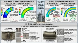
首先是剛性過大與應力集中的問題。1.5D 彎頭的曲率變化極為急促,其在吸收相鄰長直管段傳遞而來的巨大熱膨脹位移時,柔性(Flexibility)極為受限。這會導致強烈的卡門橢圓化效應(Kármán ovalization),使得管壁承受極高的局部二次薄膜應力與彎曲應力,其應力強化係數(SIF)往往居高不下17。其次,依據 ASME TDP-1(防範汽機進水規範)之強制規定,蒸汽管線必須具備嚴格的重力洩水坡度(通常為 1:100 或 1° 至 3°),以防止凝結水滯留引發水錘(Water Hammer)與汽機葉片沖蝕8。由於市售鍛造彎頭均為標準的 45° 或 90°,在複雜且狹窄的廠房三維空間中,施工人員為了達成微小的小數點級坡度角度,往往必須對 1.5D 彎頭進行強行的現場斜切或錯位組對。這種強制組對會破壞管線幾何的平順性,產生嚴重的角錯位(Angular Misalignment),進而誘導出額外的幾何應力集中係數(Km),這將與彎頭本身的 SIF 發生惡性的乘數疊加效應,成為疲勞裂紋的溫床17。First is the issue of excessive rigidity and stress concentration. The curvature change of a 1.5D elbow is extremely abrupt, severely limiting its flexibility when absorbing the massive thermal expansion displacements transmitted from adjacent straight pipe sections. This induces a strong Kármán ovalization effect, subjecting the pipe wall to extremely high local secondary membrane and bending stresses, frequently resulting in persistently high Stress Intensification Factors (SIFs)17. Secondly, according to the mandatory requirements of ASME TDP-1 (Prevention of Water Damage to Steam Turbines), steam piping must possess a strict continuous gravity drainage slope (typically 1:100, or 1° to 3°) to prevent condensate stagnation, which could trigger water hammer and turbine blade erosion8. Because commercial forged elbows come in standard 45° or 90° angles, construction personnel often must resort to forced on-site mitering or misaligned assembly of 1.5D elbows to achieve these minute, decimal-level slope angles in complex and narrow 3D plant spaces. This forced assembly destroys the geometric smoothness of the pipeline, creating severe angular misalignment, which in turn induces an additional geometric stress concentration factor (Km). This interacts with the elbow’s inherent SIF in a vicious multiplier superposition effect, forming a breeding ground for fatigue cracks17.
在冶金層面,1.5D 彎頭在轉折兩端必須依賴環向銲縫與直管相接。銲接過程高強度的熱輸入不可避免地會在母材旁形成極為脆弱的細晶區(FGHAZ)與臨界熱影響區(ICHAZ)。對於 P91/P92 鋼材而言,這些區域的析出強化相(如碳氮化物)會發生溶解與異常粗化,導致該區域在交變熱疲勞與高溫的雙重打擊下,面臨極高的「第四型潛變破裂(Type IV Creep Cracking)」風險8。同樣地,對於氨/胺液管線,銲道 HAZ 中複雜的金相組織與未完全釋放的銲接收縮殘留應力,正是觸發鹼性 SCC 的最危險地帶14。On a metallurgical level, 1.5D elbows must rely on circumferential welds at both ends to connect with straight pipes. The high heat input during the welding process inevitably forms highly vulnerable Fine-Grained Heat-Affected Zones (FGHAZ) and Inter-Critical Heat-Affected Zones (ICHAZ) adjacent to the base metal. For P91/P92 steels, the precipitation-strengthening phases (such as carbonitrides) in these regions dissolve and coarsen abnormally, exposing the area to an extremely high risk of “Type IV Creep Cracking” under the dual assault of alternating thermal fatigue and high temperatures8. Similarly, for ammonia/amine pipelines, the complex metallographic structure and incompletely relieved weld shrinkage residual stresses in the weld HAZ constitute the most dangerous zones for triggering alkaline SCC14.
1.3 3D/5D 數控冷作彎管技術之導入與本研究目的 / 1.3 Introduction of 3D/5D CNC Cold Bending Technology and Purpose of this Study
為徹底顛覆傳統 1.5D 銲接彎頭的物理與冶金限制,國際先進電廠工程界近年來積極導入 3D 乃至 5D 的數控(CNC)大半徑冷作彎管工法(Cold Bending)。該工法在常溫狀態下,透過高精密 CNC 機台施加純機械力,將無縫直管一體成型為連續的大曲率半徑彎管8。此舉不僅在宏觀幾何上完全消除了高應力轉折區的銲道,避免了錯位組對的應力疊加,更透過平緩的曲率大幅改善了內部流場的邊界層穩定性,從根本上杜絕了段塞流(Slug Flow)與流動加速腐蝕(FAC)的威脅17。To thoroughly overturn the physical and metallurgical limitations of traditional 1.5D welded elbows, the international advanced power plant engineering community has actively introduced 3D and even 5D CNC large-radius cold bending methods in recent years. This method utilizes high-precision CNC machines to apply pure mechanical force at room temperature, integrally forming seamless straight pipes into continuous, large-radius bends8. This not only macroscopically eradicates welds in high-stress transition areas and avoids the stress superposition from misaligned assemblies, but also vastly improves the boundary layer stability of internal fluid flow through its gentle curvature, fundamentally eliminating the threats of slug flow and Flow-Accelerated Corrosion (FAC)17.
然而,冷作彎管工法並非完美無缺,其在成型過程中所引發的外弧壁厚減薄(Extrados Thinning)、內弧增厚(Intrados Thickening)以及截面橢圓化,會對管線的承載能力產生複雜影響27。更為關鍵的是,為了將直管彎折至 3D/5D 規格,材料必須承受高達 10% 至 16.7% 的巨大冷作塑性應變,這在微觀冶金尺度上會引發差排密度的指數級飆升與嚴重的晶格畸變28。若未能透過科學的熱處理加以修復,這些高能量的晶格缺陷將直接成為加速高溫潛變退化與引爆 SCC 的定時炸彈28。However, the cold bending process is not flawless. The extrados thinning, intrados thickening, and cross-sectional ovalization induced during forming exert complex impacts on the pipeline’s load-bearing capacity27. More critically, to bend a straight pipe to 3D/5D specifications, the material must endure massive cold plastic strains of up to 10% to 16.7%. At the microscopic metallurgical scale, this triggers an exponential surge in dislocation density and severe lattice distortion28. If not restored through scientific heat treatment, these high-energy lattice defects will directly become ticking time bombs, accelerating high-temperature creep degradation and triggering SCC28.
因此,本研究的宗旨在於整合最新發布的 ASME B31J 規範,從力學模擬、流體幾何與材料冶金三個維度,對 CCPP 頻繁起停條件下的 1.5D 銲接彎頭與 3D/5D 冷作彎管進行深度的對比剖析。本研究將建立熱疲勞演算法,量化不同彎曲半徑對應力強化係數(SIF)、管線柔性以及最終疲勞壽命的影響;同時,針對氨/胺液管線的 SCC 特性,探討冷彎工法中次臨界感應加熱彎後熱處理(IH-PBHT)之絕對必要性,為現代調峰型 CCPP 的高能與化學管線提供兼具高度安全性與全生命週期經濟效益的設計圭臬。Therefore, the purpose of this study is to integrate the newly released ASME B31J standard to conduct an in-depth comparative analysis of 1.5D welded elbows versus 3D/5D cold-bent pipes under frequent CCPP start-stop conditions across three dimensions: mechanical simulation, fluid geometry, and material metallurgy. This study will establish a thermal fatigue algorithm to quantify the impact of different bend radii on the Stress Intensification Factor (SIF), pipeline flexibility, and ultimate fatigue life. Concurrently, addressing the SCC characteristics of ammonia/amine pipelines, it will explore the absolute necessity of subcritical induction heating post-bend heat treatment (IH-PBHT) in the cold bending process, providing a design benchmark for high-energy and chemical pipelines in modern peak-shaving CCPPs that combines high safety with full-lifecycle economic benefits.
二、 文獻回顧與規範演進 / II. Literature Review and Standard Evolution
2.1 ASME B31J 規範之誕生與 SIF 之多維度解耦 / 2.1 The Birth of the ASME B31J Standard and the Multi-Dimensional Decoupling of SIF
在管線應力分析的歷史長河中,工程師們長期仰賴美國機械工程師學會(ASME)B31.1(動力管線)與 B31.3(製程管線)規範中的附錄 D(Appendix D)來計算管件的應力強化係數(SIF, i)與柔性係數(Flexibility Factor, k)。這些基礎公式與經驗常數,源自於 A.R.C. Markl 在 1950 年代所進行的一系列懸臂樑低週期疲勞彎曲實驗10。Markl 的實驗奠定了近代管線疲勞設計的基礎,其定義 SIF 為實際組件在特定彎矩下的應力,與相同彎矩下同尺寸直管對接銲縫應力的比值32。然而,隨著工業技術的不斷演進,現代化學製程與大型電廠廣泛採用大徑厚比(D/T > 100)的薄壁管線,且廠房佈局的幾何複雜度與日俱增,舊有 Appendix D 基於單一方向載荷與小口徑厚壁管測試數據的侷限性逐漸暴露10。傳統規範對於單一管件通常僅提供一個高度保守的 SIF 綜合值,且強制假設管件對各方向的彎矩具有相同的應力強化響應,這在處理非標準空間角、薄壁挫曲以及現代 CCPP 大幅熱膨脹位移時,往往會導致過度保守的設計(例如設置巨大且不必要的膨脹環)或隱藏致命的安全盲區10。Throughout the history of piping stress analysis, engineers have long relied on Appendix D in the American Society of Mechanical Engineers (ASME) B31.1 (Power Piping) and B31.3 (Process Piping) codes to calculate Stress Intensification Factors (SIF, i) and Flexibility Factors (k) for piping components. These foundational formulas and empirical constants originated from a series of low-cycle fatigue bending tests on cantilever beams conducted by A.R.C. Markl in the 1950s10. Markl’s experiments laid the groundwork for modern piping fatigue design, defining SIF as the ratio of the stress in an actual component under a specific bending moment to the stress in a girth butt weld of a straight pipe of the same dimensions under the same moment32. However, as industrial technology continuously evolved, modern chemical processes and large power plants extensively adopted thin-walled piping with large diameter-to-thickness ratios (D/T > 100), and the geometric complexity of plant layouts grew day by day. Consequently, the limitations of the old Appendix D, based on unidirectional loading and test data from small-diameter, thick-walled pipes, were gradually exposed10. Traditional codes typically provided only a single, highly conservative composite SIF value for a component and forced the assumption that the component exhibited the same stress intensification response to bending moments from all directions. When dealing with non-standard spatial angles, thin-wall buckling, and the massive thermal expansion displacements of modern CCPPs, this often led to overly conservative designs (e.g., installing huge, unnecessary expansion loops) or concealed fatal safety blind spots10.
為了解決這個存在已久的工程盲點,ASME 技術委員會於近年來正式發布並強力推動 ASME B31J 規範《金屬管線組件應力強化係數與柔性係數之標準測試方法》31。B31J 的發布被視為管線應力分析領域的重大革命。它徹底廢除了傳統 Appendix D 中簡陋的閉合形式方程,導入了基於大規模實體應變計疲勞測試(Strain-gauge testing)以及高保真度有限元素分析(FEA)的龐大驗證數據庫31。To resolve this long-standing engineering blind spot, the ASME Technical Committee officially released and strongly promoted the ASME B31J Standard, “Stress Intensification Factors (i-Factors), Flexibility Factors (k-Factors), and Their Determination for Metallic Piping Components,” in recent years31. The release of B31J is regarded as a major revolution in the field of piping stress analysis. It completely abolished the rudimentary closed-form equations of the traditional Appendix D and introduced a vast verification database based on large-scale physical strain-gauge fatigue testing and high-fidelity Finite Element Analysis (FEA)31.
ASME B31J 最核心的技術突破,在於對力學參數進行了深度的「多維度方向性解耦」。它強制要求應力分析必須區分載荷的作用平面,將傳統單一的 SIF 拆解為面內彎曲應力強化係數(In-Plane SIF, ii)、面外彎曲應力強化係數(Out-of-Plane SIF, io)以及扭轉應力強化係數(Torsional SIF, it)32。此外,對於三通(Tee)與分支接頭,B31J 更進一步將主管(Run)與支管(Branch)的 SIF 與柔性係數獨立計算,極大地提升了分析解析度34。在 B31J 非強制附錄 A(Nonmandatory Appendix A)中,更明訂了透過實體測試與標準化 FEA 虛擬建模來推導特殊或非標準幾何管件(如極端彎曲半徑或超薄壁管)SIF 值的嚴謹程序34。而在抗塑性崩塌(Plastic Collapse)的評估上,B31J 也明確界定了持續應力指數(Sustained Stress Index, SSI),將其定義為 0.75i(並設定下限為 1.0),取代了過去忽略幾何應力集中的單一預設值,確保了管線在承受內壓與自重等持續性負載時的安全餘裕31。各大主流管線應力分析軟體(如 CAESAR II, AutoPIPE)亦已全面整合 B31J 引擎,並強烈建議 2012 年後的新建專案強制啟用此規範進行疲勞與柔性分析31。The core technological breakthrough of ASME B31J lies in the deep “multidimensional directional decoupling” of mechanical parameters. It mandates that stress analysis must distinguish the plane of load application, breaking down the traditional single SIF into an In-Plane SIF (ii), an Out-of-Plane SIF (io), and a Torsional SIF (it)32. Furthermore, for tees and branch connections, B31J calculates the SIFs and flexibility factors of the run and the branch independently, vastly improving analytical resolution34. In B31J’s Nonmandatory Appendix A, a rigorous procedure is specified for deriving SIF values for special or non-standard geometric piping components (e.g., extreme bend radii or ultra-thin-walled pipes) via physical testing and standardized FEA virtual modeling34. In assessing resistance to plastic collapse, B31J explicitly defines the Sustained Stress Index (SSI) as 0.75i (with a minimum limit set to 1.0), replacing the single default value that previously ignored geometric stress concentration, thereby ensuring a safety margin when the pipeline is subjected to sustained loads like internal pressure and deadweight31. All mainstream piping stress analysis software (such as CAESAR II, AutoPIPE) have fully integrated the B31J engine and strongly recommend making this standard mandatory for fatigue and flexibility analysis in new projects subsequent to 201231.
2.2 低週期熱疲勞動力學:Coffin-Manson 模型與 B31.3 疲勞曲線之演化/ 2.2 Low-Cycle Thermal Fatigue Dynamics: Coffin-Manson Model and the Evolution of the B31.3 Fatigue Curve
在 CCPP 頻繁起停的過程中,管線經歷的是典型的低週期高應變疲勞(Low-Cycle High-Strain Fatigue, LCF)。不同於主要受彈性應力驅動的高週期疲勞,LCF 的主要損傷機制源於材料在熱循環中反覆發生的塑性變形。在微觀力學中,Coffin-Manson 模型完美地描述了這種行為,其方程式定義了塑性應變幅(Plastic Strain Amplitude, Δϵp)與疲勞失效循環次數(Nf)之間的對數線性關係43。在熱瞬態過程中,管線截面內外壁之間巨大的溫度梯度轉化為龐大的熱應力,當此應力超越材料的屈服強度時,即會產生不可逆的塑性應變;隨後的冷卻過程再次引發反向的塑性變形,這種反覆的「包辛格效應(Bauschinger effect)」與熱潛變(Creep)交替作用,最終導致微裂紋在晶界處成核並迅速貫穿管壁44。During the frequent start-stop cycles of CCPPs, pipelines undergo typical Low-Cycle High-Strain Fatigue (LCF). Unlike high-cycle fatigue, which is primarily driven by elastic stress, the main damage mechanism in LCF originates from the repeated plastic deformation of the material during thermal cycling. In micromechanics, the Coffin-Manson model perfectly describes this behavior; its equation defines a logarithmic linear relationship between the Plastic Strain Amplitude (Δϵp) and the number of cycles to fatigue failure (Nf)43. During thermal transients, the massive temperature gradient between the inner and outer walls of the pipe cross-section translates into immense thermal stresses. When this stress exceeds the material’s yield strength, irreversible plastic strain occurs. The subsequent cooling process induces reverse plastic deformation again. This repeated “Bauschinger effect,” alternating with thermal creep, ultimately leads to micro-cracks nucleating at grain boundaries and rapidly penetrating the pipe wall44.
為了將這些微觀材料力學理論轉化為工程設計規範,ASME B31.3 採用了基於位移控制(Displacement-controlled)的位移應力範圍(Displacement Stress Range, SE)來評估熱膨脹所累積的疲勞損傷33。傳統上,B31.3 的熱疲勞評估奠基於 Markl 的應力-壽命(S-N)對數曲線,其隱含的疲勞曲線斜率長達半世紀以來皆維持在 5:1,對應的應力範圍縮減因子公式為 f=6.0N-0.2 23。然而,根據近年來產業界針對現代高強合金與複雜管件累積的大量 LCF 破壞數據,ASME 委員會認知到舊有斜率低估了高應力幅對疲勞壽命的殺傷力。因此,在發布的 ASME B31.3-2022 版(於 2023 年生效)中,進行了歷史性的重大修訂,將隱含的 S-N 曲線斜率從 5:1 陡降至 3:1,對應的縮減因子公式被修正為 f=20N-0.333 42。To translate these micro-material mechanics theories into engineering design codes, ASME B31.3 adopted the displacement-controlled Displacement Stress Range (SE) to evaluate the accumulated fatigue damage caused by thermal expansion33. Traditionally, the B31.3 thermal fatigue evaluation was founded upon Markl’s Stress-Life (S-N) logarithmic curve, whose implied fatigue curve slope remained at 5:1 for half a century; the corresponding stress range reduction factor formula was f=6.0N-0.2 23. However, based on the vast amount of LCF failure data accumulated by the industry in recent years concerning modern high-strength alloys and complex piping components, the ASME committee recognized that the old slope underestimated the lethality of high stress amplitudes on fatigue life. Consequently, in the released ASME B31.3-2022 edition (effective in 2023), a historic and major revision was made, sharply dropping the implied S-N curve slope from 5:1 to 3:1, with the corresponding reduction factor formula revised to f=20N-0.333 42.
這一法規的根本性變動在工程實務上引發了劇烈震盪:它意味著管線的疲勞壽命對於熱膨脹應力幅的敏感度呈現指數級的放大。在相同的熱膨脹應力範圍下,採用新版 3:1 斜率計算出的允許循環次數,將遠低於舊版 5:1 的結果23。這使得傳統高 SIF、高剛性的 1.5D 銲接彎頭,在面對 CCPP 動輒上萬次的起停循環需求時,其位移應力極易超出允許範圍而判定為不合格。這也迫使工程設計界必須尋求具有更低應力集中效應的替代方案,亦即全面轉向 B31J 框架下具備極低 SIF 特性的 3D/5D 大半徑冷作彎管33。This fundamental regulatory shift triggered massive tremors in engineering practice: it implies that the pipeline’s fatigue life sensitivity to thermal expansion stress amplitudes is amplified exponentially. Under the same thermal expansion stress range, the allowable number of cycles calculated using the new 3:1 slope will be far lower than the results under the old 5:1 slope23. This makes it highly likely that traditional high-SIF, high-rigidity 1.5D welded elbows will exceed allowable displacement stress limits and be deemed unqualified when facing the tens of thousands of start-stop cycling demands of CCPPs. This has forced the engineering design community to seek alternatives with lower stress concentration effects, namely an across-the-board shift to 3D/5D large-radius cold-bent pipes, which possess extremely low SIF characteristics under the B31J framework33.
2.3 氨/胺液管線之應力腐蝕破裂 (SCC) 冶金機制與防護規範 / 2.3 Metallurgical Mechanisms and Protection Standards for Stress Corrosion Cracking (SCC) in Ammonia/Amine Piping
在 CCPP 的減排核心—選擇性催化還原系統(SCR)中,無水氨(Anhydrous Ammonia)與各類胺液(如單乙醇胺 MEA、二乙醇胺 DEA 等)被廣泛運用。然而,這些鹼性化學物質卻是誘發碳鋼與低合金鋼發生應力腐蝕破裂(SCC)的極危險介質8。In the emission reduction core of CCPPs—the Selective Catalytic Reduction (SCR) system—anhydrous ammonia and various amine solutions (such as Monoethanolamine (MEA) and Diethanolamine (DEA)) are widely utilized. However, these alkaline chemicals are highly dangerous media that induce Stress Corrosion Cracking (SCC) in carbon steel and low-alloy steel8.
液氨應力腐蝕破裂 (Ammonia SCC) 是一種典型的環境輔助破裂。文獻與實務案例表明,液氨 SCC 的發生需滿足三大條件的重合:敏感的材料(如高強度碳鋼)、特定的腐蝕環境以及持續存在的拉伸應力(無論是工作應力或是加工/銲接殘留應力)13。在化學機制上,液氨系統中的微量氧氣扮演著至關重要的催化角色。當氨中的溶氧量超過極微小的極限值(通常只需大於 0.5 ppm 至 2.5 ppm),便會破壞碳鋼表面的鈍化保護膜,在拉應力的拉扯下,裸露的金屬晶界成為陽極迅速溶解,形成尖銳的微觀缺口,並沿著晶間(Intergranular)或穿晶(Transgranular)路徑迅速擴展成巨觀裂紋16。國際海事組織(IMO)與多數工業規範建議,透過在液氨中添加至少 0.2% 的水分,可有效抑制氧氣的活性並重塑鈍化膜,從而降低 SCC 風險;然而,從根本的材料力學層面著手,降低系統的殘留應力才是治本之道13。Ammonia Stress Corrosion Cracking (Ammonia SCC) is a typical environmentally-assisted cracking. Literature and practical case studies demonstrate that the occurrence of ammonia SCC requires the convergence of three major conditions: susceptible materials (such as high-strength carbon steel), a specific corrosive environment, and the sustained presence of tensile stress (whether operational or residual stresses from machining/welding)13. Mechanistically, trace amounts of oxygen in the liquid ammonia system play a crucial catalytic role. When the dissolved oxygen content in ammonia exceeds a minuscule threshold (typically just 0.5 ppm to 2.5 ppm), it compromises the passivation protective film on the carbon steel surface. Under the pull of tensile stress, the exposed metal grain boundaries become rapid-dissolving micro-anodes, forming sharp microscopic notches that swiftly propagate into macroscopic cracks along intergranular or transgranular paths16. The International Maritime Organization (IMO) and most industrial codes recommend that adding a minimum of 0.2% water to liquid ammonia can effectively inhibit oxygen activity and rebuild the passivation film, thereby reducing SCC risks. However, tackling the root cause from a material mechanics perspective by lowering the system’s residual stress is the true cure13.
胺液應力腐蝕破裂 (Amine SCC) 亦被稱為鹼性應力腐蝕破裂(Alkaline SCC)。在 SCR 系統或煉油廠的胺液再生單元中,高溫胺液會對碳鋼管線的銲接熱影響區(HAZ)發動猛烈攻擊14。HAZ 中因銲接熱循環而產生的淬硬組織(高硬度麻田散鐵或變韌鐵),加上高達材料屈服強度的銲接收縮殘留拉應力,為胺液 SCC 提供了完美的物理與冶金溫床。裂紋通常從銲趾處萌生,呈輻射狀或平行於銲縫向內發展。為防範此一災難,美國石油學會發布了 API RP 945《避免胺液裝置環境開裂》與 API 571 損害機制規範,其中強制規定,所有暴露於胺液環境的碳鋼與低合金鋼管線、容器及其銲縫,均必須實施嚴格的銲後熱處理(Post-Weld Heat Treatment, PWHT),以將殘留拉應力降至安全極限值以下,並軟化 HAZ 組織,這是目前業界公認對抗胺液 SCC 唯一且最有效的工程防護措施14。Amine Stress Corrosion Cracking (Amine SCC) is also known as Alkaline SCC. In SCR systems or amine regeneration units in refineries, high-temperature amine solutions launch fierce attacks directly on the weld Heat-Affected Zone (HAZ) of carbon steel piping14. The hardened microstructures (high-hardness martensite or bainite) formed in the HAZ due to welding thermal cycles, coupled with weld shrinkage residual tensile stresses matching the material’s yield strength, provide a perfect physical and metallurgical breeding ground for amine SCC. Cracks typically initiate at the weld toes, developing radially or parallel to the weld seam inward. To prevent this catastrophe, the American Petroleum Institute issued API RP 945 (“Avoiding Environmental Cracking in Amine Units”) and API 571 damage mechanism standards. These mandate that all carbon and low-alloy steel piping, vessels, and their welds exposed to amine environments undergo strict Post-Weld Heat Treatment (PWHT) to reduce residual tensile stresses below a safe threshold and soften the HAZ structure. This is currently recognized as the industry’s singular and most effective engineering countermeasure against amine SCC14.
三、 分析模型與理論構建 / III. Analytical Models and Theoretical Construction
為了科學地量化並對比傳統 1.5D 銲接彎頭與先進 3D/5D CNC 冷作彎管在 CCPP 頻繁起停熱循環下的表現,本研究依據 ASME B31J 規範構建了包含幾何柔性、應力集中與疲勞壽命的綜合分析模型。To scientifically quantify and compare the performance of traditional 1.5D welded elbows and advanced 3D/5D CNC cold-bent pipes under frequent CCPP start-stop thermal cycles, this study constructs a comprehensive analytical model incorporating geometric flexibility, stress concentration, and fatigue life based on the ASME B31J standard.
3.1 B31J 柔性特徵值與應力強化係數解耦模型 / 3.1 B31J Flexibility Characteristic and SIF Decoupling Model
在彈性力學中,曲管在承受彎矩時會發生管壁的橢圓化變形,這種變形改變了截面的慣性矩,從而影響管線整體的柔性與局部應力分佈。ASME B31J 使用無因次的「柔性特徵值(Flexibility Characteristic, h)」來量化此一幾何抵抗能力,其公式為:In elasticity mechanics, curved pipes undergo an ovalization deformation of the pipe wall when subjected to a bending moment. This deformation alters the cross-sectional moment of inertia, thereby affecting the overall flexibility and local stress distribution of the pipeline. ASME B31J uses a dimensionless “Flexibility Characteristic” (h) to quantify this geometric resistance capacity, given by the formula:
h=T⋅R1/r22
其中:Where:
- T 為管件公稱壁厚( 或 mm)T is the nominal wall thickness of the component (in. or mm)
- R1 為彎曲半徑(Bend Radius, 如5D, 3D, 5D)(in. 或 mm)R1 is the bend radius (e.g., 1.5D, 3D, 5D) (in. or mm)
- r2為與管件匹配之直管平均截面半徑,r2=(OD-T)/2( 或 mm)r2 is the mean cross-sectional radius of the matching straight pipe, r2=(OD-T)/2 (in. or mm)
由方程式可知,柔性特徵值 h 與彎曲半徑 R1 呈現正向的線性關係。h 值越大,代表管件截面越不容易發生劇烈的橢圓化扁平現象。 基於 h 值,B31J 規範針對彎管(Bend/Elbow)定義了精確解耦的多維度係數17:From the equation, the flexibility characteristic h exhibits a positive linear relationship with the bend radius R1. A larger h value indicates that the component’s cross-section is less susceptible to severe ovalization and flattening. Based on the h value, the B31J code defines precisely decoupled multidimensional coefficients for bends/elbows17:
- 柔性係數 (Flexibility Factor, k):用以修正直管剛度矩陣,反映彎管增加的宏觀變形能力。Flexibility Factor (k): Used to modify the stiffness matrix of a straight pipe, reflecting the increased macroscopic deformability of the bend.
K=1.65/h
- 面內應力強化係數 (In-Plane SIF, ii ):當彎矩作用於彎管所在的平面內,導致彎頭有「張開」或「閉合」趨勢時的應力放大倍數。In-Plane SIF (ii): The stress amplification factor when the bending moment acts within the plane of the bend, causing the elbow to tend to “open” or “close.”
ii=max(0.9/h2/3 ,1.0)
- 面外應力強化係數 (Out-of-Plane SIF, io):當彎矩作用垂直於彎管所在平面,導致彎頭發生「扭曲」時的應力放大倍數。Out-of-Plane SIF (io): The stress amplification factor when the bending moment acts perpendicularly to the plane of the bend, causing the elbow to “twist.”
Io=max(0.75/h2/3 ,1.0)
- 持續應力指數 (Sustained Stress Index, SSI):用於核算壓力與重力等一次應力造成的塑性降伏風險。Sustained Stress Index (SSI): Used to calculate the risk of plastic yielding caused by primary stresses such as pressure and gravity.
SSIi=max(0.75 • ii,1.0) ; SSIo=max(0.75 • io,1.0)
此外,對於 CCPP 系統中常見的高壓或大口徑薄壁蒸汽管線,強大的內部流體壓力會抵抗管壁向內凹陷的橢圓化趨勢,這種被稱為「壓力強化效應(Pressure Stiffening Effect)」的物理現象,會使得彎管變得較為僵硬(k 值下降),同時 SIF 也會相應降低。在 B31J 的完整演算法中,會導入基於設計壓力、楊氏模數與截面幾何的修正因子來精確微調這些參數39。Additionally, for high-pressure or large-diameter, thin-walled steam pipes commonly found in CCPP systems, the immense internal fluid pressure resists the inward denting ovalization trend of the pipe wall. This physical phenomenon, known as the “Pressure Stiffening Effect,” stiffens the pipe bend (reducing the k value), while the SIF correspondingly decreases. In the complete B31J algorithm, correction factors based on design pressure, Young’s modulus, and cross-sectional geometry are introduced to fine-tune these parameters accurately39.
3.2 角錯位應力集中係數 (Km) 之導入與惡性疊加效應 / 3.2 Introduction of Angular Misalignment Stress Concentration Factor (Km) and the Vicious Superposition Effect
在理想的數學模型中,彎頭與直管的連接是絕對平順的。然而,在真實的電廠建置實務中,為了滿足 ASME TDP-1 規範對於蒸汽管線 1:100 或特定度數(1°~3°)的重力洩水坡度要求,傳統固定規格(45°/90°)的 1.5D 鍛造彎頭面臨了嚴重的幾何不相容問題8。為了解決空間角度不匹配的問題,現場施工通常被迫採用兩種破壞性手段:一是不均勻的斜切加工,二是依靠吊車或倒鏈進行強行逼近錯位組對。這不可避免地在對銲接頭處產生了角錯位(Angular Misalignment)。這種軸線偏移破壞了受力截面的對稱性,導致軸向拉伸應力在此處轉化為強烈的次級彎曲應力與應力集中。In an ideal mathematical model, the connection between an elbow and a straight pipe is absolutely smooth. However, in actual power plant construction practices, traditional fixed-specification (45°/90°) 1.5D forged elbows face severe geometric incompatibility issues to meet the ASME TDP-1 code requirements for a 1:100 or specific degree (1°~3°) gravity drainage slope for steam piping8. To resolve spatial angle mismatches, on-site construction is often forced to employ two destructive measures: first, uneven mitering; second, relying on cranes or chain hoists to forcefully align and assemble the joint. This inevitably creates an angular misalignment at the butt weld joint. This axial offset destroys the symmetry of the load-bearing cross-section, causing axial tensile stress to translate into intense secondary bending stresses and stress concentration at this location.
在疲勞評估中,這種因施工幾何偏差產生的應力集中係數(SCF,在此定義為 Km)通常落於 1.2 至 1.5 之間(本研究取保守預估值 Km=1.3)42。最致命的是,這個因銲道錯位產生的 Km,會與 B31J 理論計算出的 SIF 發生數學上的「惡性乘數疊加」。當系統承受熱膨脹產生面內彎矩 Mi、面外彎矩 Mo 與扭矩 Mt 時,位於 1.5D 錯位銲道處的有效熱膨脹位移應力範圍(SEeff)將被巨幅放大:In fatigue evaluations, the Stress Concentration Factor (SCF, defined here as Km) generated by such construction geometric deviations typically falls between 1.2 and 1.5 (this study adopts a conservative estimate of Km=1.3)42. Most fatally, this Km, resulting from weld misalignment, mathematically undergoes a “vicious multiplier superposition” with the SIF theoretically calculated by B31J. When the system bears thermal expansion, producing in-plane bending moment Mi, out-of-plane bending moment Mo, and torsional moment Mt, the effective thermal expansion displacement stress range (SEeff) located at the 1.5D misaligned weld is massively amplified:
SEeff=Km•√((iiMi)2+(ioMo)2+(itMt)2 )/Z
相對而言,3D/5D 數控冷作彎管透過機台直接輸入空間座標與角度,一體成型出包含小數點的精確幾何非標準坡度,管線保持絕對連續,因此其 Km 恆等於理想值 1.0,完全避開了此一應力疊加陷阱42。Conversely, 3D/5D CNC cold-bent pipes, by directly inputting spatial coordinates and angles into the machine, integrally form precise non-standard slopes containing decimals. The pipeline maintains absolute continuity, ensuring its Km is constantly equal to the ideal value of 1.0, thereby entirely bypassing this stress superposition trap42.
3.3 低週期熱疲勞壽命模擬算法 / 3.3 Low-Cycle Thermal Fatigue Life Simulation Algorithm
本研究採用基於應力範圍幅度的低週期疲勞算法來預測管線壽命。依據 ASME B31.3 與 Markl 實驗的衍生關係,材料的容許疲勞循環次數 N 與所承受的有效熱膨脹應力範圍 SEeff滿足指數反比關係。本研究採用的疲勞模擬基線公式為42:This study employs a stress-range-amplitude-based low-cycle fatigue algorithm to predict pipeline life. Deriving from the ASME B31.3 and Markl’s experiments, the material’s allowable number of fatigue cycles N satisfies an inverse exponential relationship with the endured effective thermal expansion stress range SEeff. The baseline formula for fatigue simulation used in this study is42:
N=(C/(SEeff ))m
其中 C 為與材料特性相關的常數(對於典型碳鋼/合金鋼管線,常取 245,對應 SE 單位為 ksi),m 為疲勞曲線指數(傳統取 5,呼應舊版規範;若依 B31.3-2022 新版斜率精神,對高應力的懲罰將更為嚴厲,為便於與過往工程數據對比,本節數值模擬暫採古典 5 次方指數展示基礎趨勢)42。透過將不同彎管的 SIF 與 Km 帶入上述體系,即可客觀量化不同彎曲半徑對 CCPP 起停壽命的深遠影響。Where C is a constant related to material properties (for typical carbon/alloy steel pipelines, C is usually 245 when the unit of SE is ksi), and m is the fatigue curve exponent (traditionally 5, echoing older codes; although according to the B31.3-2022 new slope spirit, the penalty for high stress will be more severe, for the convenience of comparing with past engineering data, this section’s numerical simulation temporarily uses the classical power of 5 to demonstrate fundamental trends)42. By substituting the SIFs of different bends and Km into the above system, one can objectively quantify the profound impact of varying bend radii on the start-stop lifespan of a CCPP.
四、 高能蒸汽管線與排液坡度之三維應力與疲勞模擬分析 / IV. 3D Stress and Fatigue Simulation Analysis of High-Energy Steam Piping and Drainage Slopes
4.1 幾何與力學基準設定 / 4.1 Geometric and Mechanical Baseline Settings
為具體展現 SIF 解耦與疲勞壽命的差異,本研究建立了一個模擬 CCPP 輔助高壓蒸汽管線的典型運轉場景。管線規格設定為 10 吋(Nominal Pipe Size),Schedule 80 的厚壁管,材質可為 P91 高溫合金鋼或優質碳鋼。To concretely demonstrate the differences resulting from SIF decoupling and fatigue life, this study establishes a typical operational scenario simulating an auxiliary high-pressure steam line in a CCPP. The piping specification is set as a 10-inch (Nominal Pipe Size), Schedule 80 heavy-wall pipe. The material could be P91 high-temperature alloy steel or premium carbon steel.
- 外徑 (OD) / Outer Diameter (OD) = 10.75 in (approx. 273 mm)
- 公稱壁厚 (T) / Nominal Wall Thickness (T) = 0.500 in (approx. 12.7 mm)
- 平均半徑 (r2) / Mean Radius (r2) = (10.75 – 0.5) / 2 = 5.125 in
模擬情境設定為 CCPP 從冷機啟動至滿載運轉(Cold Start to Base Load)的一次完整熱循環。假設透過整體驗積彈性分析,由系統熱膨脹位移所產生、作用於管件端點的標稱位移應力範圍(未乘上 SIF 前的基礎應力,Snom=M/Z)為 120 MPa(約合 17.4 ksi)42。The simulation scenario is set as one complete thermal cycle of the CCPP from a cold start to base load operation. It is assumed that, through global elastic system analysis, the nominal displacement stress range (baseline stress before multiplying by the SIF, Snom=M/Z) generated by the system’s thermal expansion displacement and acting on the component endpoints is 120 MPa (approx. 17.4 ksi)42.
4.2 彎曲半徑 (1.5D vs 3D vs 5D) 對 SIF 與疲勞壽命之數值解析 / 4.2 Numerical Analysis of Bend Radius (1.5D vs. 3D vs. 5D) on SIF and Fatigue Life
依據前述 B31J 演算法,針對「1.5D 銲接彎頭(伴隨Km=1.3 的現場錯位)」、「3D CNC 冷作彎管(無錯位,Km=1.0)」以及「5D CNC 冷作彎管(無錯位,Km=1.0)」三種常見構型進行深度數值解析。計算結果如表 1 所示。
Based on the aforementioned B31J algorithm, in-depth numerical analyses were conducted for three common configurations: “1.5D Welded Elbow (accompanied by field misalignment Km=1.3),” “3D CNC Cold Bend (no misalignment, Km=1.0),” and “5D CNC Cold Bend (no misalignment, Km=1.0).” The calculation results are shown in Table 1.
表 1:不同彎曲半徑在 ASME B31J 下之 SIF、剛度與熱疲勞壽命比較 [cite: 42] / Table 1: Comparison of SIF, Stiffness, and Thermal Fatigue Life under ASME B31J for Different Bend Radii [cite: 42]
| 參數指標 (Parameter) | 1.5D 銲接彎頭 (含角錯位) / 1.5D Welded Elbow (w/ Misalignment) | 3D CNC 冷作彎管 / 3D CNC Cold Bend | 5D CNC 冷作彎管 / 5D CNC Cold Bend | 深度物理意義與工程影響 (Physical Meaning & Engineering Impact) |
| 幾何彎曲半徑 R1 (in)/
(Bend Radius) |
16.125 | 32.250 | 53.750 | 決定管線幾何變化梯度的急促程度,直接影響橫截面橢圓化阻力。/
(Determines the abruptness of the pipeline’s geometric change gradient, directly affecting the cross-sectional ovalization resistance.) |
| 柔性特徵值 h/
(Flexibility Characteristic) |
0.3070 | 0.6139 | 1.0232 | h 隨 R1 線性增長;數值越小,代表承受彎矩時截面越容易發生嚴重的壓扁與應力集中。/
(h grows linearly with R1; a smaller value means the cross-section is more prone to severe flattening and stress concentration under bending moments.) |
| 柔性係數 k/
(Flexibility Factor) |
5.3753 | 2.6876 | 1.6126 | 關鍵權衡 (Key Trade-off):1.5D 雖然應力大,但具有極高的彎折柔性;5D 彎管 k 值大幅下降,形同「高剛性樞紐」,設計時需防範過大的終端推力。/
(While 1.5D bears high stress, it possesses extremely high bending flexibility; the k value of a 5D bend drops significantly, acting as a “high-rigidity pivot.” Designs must prevent excessive terminal thrust.) |
| 面內 SIF (ii)/
(In-Plane SIF) |
1.9778 | 1.2460 | 1.0000 | 5D 彎管的大半徑使面內應力集中效應徹底消弭,完美收斂至 B31J 規範的理論下限(1.0)。/
(The large radius of the 5D bend utterly eliminates in-plane stress concentration, converging perfectly to the B31J theoretical lower limit of 1.0.) |
| 面外 SIF (io)/
(Out-of-Plane SIF) |
1.6482 | 1.0383 | 1.0000 | 3D 冷作彎管在面外彎曲已極度逼近直管理想狀態,5D 則完全等同於直管。/
(The 3D cold bend closely approximates the ideal state of a straight pipe in out-of-plane bending; the 5D is completely equivalent to a straight pipe.) |
| 角錯位係數 Km /
(Misalignment Factor) |
1.3000 | 1.0000 | 1.0000 | 1.5D 現場切削組對極易產生錯位 SCF;CNC 彎管則憑藉機台數據驅動維持絕對幾何連續性。/
(1.5D field cutting and assembly easily generate a misalignment SCF; CNC bends maintain absolute geometric continuity driven by machine data.) |
| 有效熱應力幅 SEeff (MPa)/
(Effective Thermal Stress Range) |
308.46 | 149.47 | 119.97 | 1.5D 在自身高 SIF 與外部 Km雙重惡性疊加下,局部應力飆升逾 2.5 倍。/
(Under the dual vicious superposition of its own high SIF and external Km, the local stress of the 1.5D surges over 2.5 times.) |
| 熱疲勞壽命 N (預估循環數)/
(Thermal Fatigue Life – Est. Cycles) |
4,925 | 184,322 | 553,457 | 壓倒性優勢 (Overwhelming Advantage):5D CNC 冷作彎管的疲勞抵抗力為傳統 1.5D 錯位組對彎頭的 112 倍。/
(The fatigue resistance of a 5D CNC cold bend is 112 times that of a traditional misaligned 1.5D welded elbow.) |
(註:本表數據由 Python 數學腳本依據 B31J 解析解精確運算得出,以展示理論趨勢42) (Note: The data in this table were accurately computed via a Python mathematical script based on B31J analytical solutions to demonstrate theoretical trends42)
深度洞察與討論 (Deep Insight and Discussion): 表 1 的數據結果揭示了一個在 CCPP 管線設計中極具震撼力的事實:幾何連續性的破壞,是低週期熱疲勞的萬惡之源。對於現代需要執行每日起停(Two-shifting)的 CCPP 機組而言,一年可能面臨 300 次以上的全負荷熱循環。如果採用傳統的 1.5D 銲接彎頭且不可避免地發生了現場組對錯位,其僅有 4,925 次的熱疲勞壽命意味著,該管線在極端情況下可能在運轉短短 15 年內,即會在銲道處萌生並貫穿疲勞裂紋。相對地,5D CNC 冷作彎管憑藉著 ii=1.0、io=1.0以及無錯位 Km=1.0 的「三重完美狀態」,將有效熱應力控制在基礎標稱值,其熱疲勞壽命呈現指數級暴增至驚人的 55 萬次以上。這種高達 112 倍的壽命躍升幅度,遠遠超出了任何電廠 30 至 40 年全生命週期的最高極限需求,為高能氣體管線提供了堅不可摧的安全餘裕。The data results in Table 1 reveal a profoundly shocking fact in CCPP piping design: the destruction of geometric continuity is the root of all evil in low-cycle thermal fatigue. For modern CCPP units requiring daily start-stops (two-shifting), they might face over 300 full-load thermal cycles in a single year. If traditional 1.5D welded elbows are used and on-site assembly misalignment inevitably occurs, a thermal fatigue life of merely 4,925 cycles means that, under extreme conditions, the pipeline could initiate and propagate fatigue cracks through the weld within just 15 years of operation. Conversely, relying on the “triple perfect state” of ii=1.0、io=1.0, and a misalignment-free Km=1.0, the 5D CNC cold-bent pipe restricts the effective thermal stress to the basic nominal value. Its thermal fatigue life explodes exponentially to an astounding 550,000+ cycles. This 112-fold leap in lifespan far exceeds the maximum limit requirements of any power plant’s 30 to 40-year full life cycle, providing an indestructible safety margin for high-energy gas pipelines.
4.3 ASME TDP-1 洩水坡度對終端反力與流體力學之三維耦合影響 / 4.3 3D Coupling Impact of ASME TDP-1 Drainage Slopes on Terminal Reactions and Fluid Dynamics
在 CCPP 蒸汽管線設計中,力學安全與流體物理往往必須同時兼顧。為了防止在起停過程或低負載運轉時,管內積聚的濕蒸汽冷凝水被高速蒸汽捲起而引發毀滅性的水錘(Water Hammer)與管件沖刷(FAC),ASME TDP-1 規範嚴格要求管線必須具備適當的重力洩水坡度(Drainage Slope)20。然而,這種坡度要求卻對管線的三維應力分佈帶來了極大的幾何干涉。In CCPP steam piping design, mechanical safety and fluid physics must often be balanced simultaneously. To prevent wet steam condensate accumulated in the pipes during start-stop processes or low-load operations from being swept up by high-speed steam, which could trigger devastating water hammer and Flow-Accelerated Corrosion (FAC) in fittings, the ASME TDP-1 code strictly demands that pipelines must possess an appropriate gravity drainage slope20. However, this slope requirement imposes immense geometric interference on the pipeline’s 3D stress distribution.
實務上,不同的洩水坡度設計會產生截然不同的物理後果22:In practice, different drainage slope designs produce radically different physical consequences22:
- 1° 坡度設計(常規基礎配置,梯度約75%):在 100 公尺的水平走向中會產生約 1.75 公尺的垂直落差。此落差較為平緩,彈簧吊架(Spring Hangers)仍能輕易消化熱位移。但其重力驅動力較弱,若管線因高溫潛變發生輕微下垂(Sagging),極易形成冷凝水滯留池。1° Slope Design (Standard Baseline Configuration, approx. 1.75% gradient): This creates a vertical drop of roughly 1.75 meters over a 100-meter horizontal run. This drop is relatively mild, and Spring Hangers can still easily absorb the thermal displacement. However, its gravitational driving force is weak; if the pipeline undergoes slight sagging due to high-temperature creep, condensate pooling areas can easily form.
- 2° 坡度設計(強化排液配置,梯度約49%):大幅提升了冷凝水的排淨效率,極度適合頻繁起停的調峰機組。但 100 公尺長度將累積高達 3.49 公尺的高程變化,這會導致整個管系的重心發生顯著偏移,對固定支架與導向支架施加不容忽視的額外摩擦力與剪力,增加了邊界條件應力評估的複雜性。2° Slope Design (Enhanced Drainage Configuration, approx. 3.49% gradient): This vastly improves the clearance efficiency of condensate, making it highly suitable for peak-shaving units undergoing frequent start-stops. Yet, a 100-meter length will accumulate an elevation change of up to 3.49 meters, causing a significant shift in the entire piping system’s center of gravity. This imposes non-negligible additional friction and shear forces on fixed and guide supports, complicating boundary condition stress evaluations.
- 3° 坡度設計(極端防護配置,梯度約24%):能帶來近乎完美的排液效果,徹底根除冷凝水滯留。然而,其 100 公尺管段高達 5.24 公尺的巨大垂直落差,在工程實務上意味著管線必須強行穿越多個廠房樓層或鋼構標高。更致命的是,這種大坡度強烈干涉了管系原本在水平面(XY 軸)內的自然柔性熱膨脹路徑,將巨大的熱位移推力強行轉向垂直(Z 軸)方向。3° Slope Design (Extreme Protection Configuration, approx. 5.24% gradient): This provides near-perfect drainage effects, totally eradicating condensate stagnation. However, its massive vertical drop of 5.24 meters over a 100-meter segment practically implies that the pipeline might be forced to cut through multiple plant floors or structural steel elevations. More fatally, this steep slope strongly interferes with the piping system’s natural flexible thermal expansion path within the horizontal plane (XY axis), forcing massive thermal displacement thrusts to divert into the vertical (Z axis) direction.
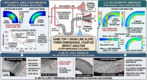
在此極端坡度情境下,表 1 中 3D/5D 冷作彎管的「雙刃劍」特性便完全展露:雖然 5D 彎管的應力集中 SIF 極低,但其柔性係數 k 亦同時降至最低(5D 的k=1.61,遠低於 1.5D 的k=5.37)22。這意味著 5D 彎管是一段難以被彎折的「高剛性結構」。 深度洞察:當高剛性的 5D 彎管遇到 3° 的大傾角坡度時,管線的熱膨脹應變能無法輕易地在轉折處被吸收,而是會化為巨大且難以化解的終端反力(Terminal Reactions),直接衝擊高單價且脆弱的汽機(Steam Turbine)與鍋爐設備管口17。因此,應力分析工程師在採用 5D 冷作彎管時,絕不能單純迷信其「低 SIF」優勢,必須在管線佈局(Routing)初期,透過延長膨脹環(Expansion Loops)的跨距,或利用 CNC 冷彎工法可無縫製作複雜三維立體折彎的特性,來吸收被轉向的熱推力。唯有將 B31J 力學模型與三維幾何拓撲進行整體規劃,方能在不增加終端反力的前提下,享受大半徑彎管杜絕分離泡(Separation Bubbles)與迪恩渦流(Dean Vortices)、徹底消滅段塞流的完美流體力學效益17。Under this extreme slope scenario, the “double-edged sword” characteristic of the 3D/5D cold-bent pipes from Table 1 is fully exposed: while the stress concentration SIF of a 5D bend is extremely low, its flexibility factor k simultaneously drops to the lowest (the k=1.61 of 5D is far lower than the k=5.37 of 1.5D)22. This implies that the 5D bend acts as a highly rigid structure that is difficult to flex. Deep Insight: When a highly rigid 5D bend encounters a steep 3° incline, the pipeline’s thermal expansion strain energy cannot be easily absorbed at the directional change. Instead, it transforms into massive, intractable Terminal Reactions that directly strike the expensive and fragile nozzles of the Steam Turbine and boiler (HRSG)17. Therefore, when adopting 5D cold-bent pipes, stress analysis engineers must not blindly trust the “low SIF” advantage. During the initial piping routing phase, they must extend the span of Expansion Loops or utilize the CNC cold bending method’s ability to seamlessly manufacture complex 3D spatial bends to absorb the diverted thermal thrust. Only by holistically planning the B31J mechanical models alongside the 3D geometric topology can one enjoy the perfect fluid dynamic benefits of large-radius bends—such as eliminating separation bubbles, Dean vortices, and slug flow—without increasing terminal reactions17.
五、 氨/胺液管線 SCC 防護機制與冷作彎管冶金特徵之深度探討 / V. In-Depth Discussion on SCC Protection Mechanisms for Ammonia/Amine Piping and Metallurgical Characteristics of Cold-Bent Pipes
如果說高能蒸汽管線面臨的是物理層面的「熱疲勞撕裂」,那麼 CCPP 中為了 SCR 系統而佈建的液氨與胺液管線,面臨的則是化學與力學交織的「應力腐蝕破裂(SCC)吞噬」。在這場對抗腐蝕的戰爭中,冷作彎管技術展現了極具顛覆性的優勢,但也隱藏了必須被嚴肅對待的冶金陷阱。If high-energy steam piping faces a physical “thermal fatigue tearing,” then the liquid ammonia and amine pipelines deployed for the SCR system in CCPPs face an intertwined chemical and mechanical “Stress Corrosion Cracking (SCC) devouring.” In this war against corrosion, cold bending technology demonstrates deeply disruptive advantages, yet it also harbors metallurgical pitfalls that must be treated seriously.
5.1 氨與胺液之微觀應力腐蝕破裂 (SCC) 物理化學機制 / 5.1 Microscopic SCC Physical and Chemical Mechanisms in Ammonia and Amines
無水氨(Anhydrous Ammonia)與各類胺液(如 MEA, DEA, MDEA)在 CCPP 中被廣泛應用,但它們對碳鋼與低合金鋼具有極強的化學侵蝕性。這類破壞屬於環境輔助破裂(Environmentally-Assisted Cracking),其發生取決於材料、環境化學與應力的致命重合。Anhydrous ammonia and various amine solutions (e.g., MEA, DEA, MDEA) are widely applied in CCPPs, but they possess extremely strong chemical corrosiveness toward carbon and low-alloy steels. This type of damage belongs to Environmentally-Assisted Cracking, the occurrence of which depends on the fatal convergence of materials, environmental chemistry, and stress.
液氨 SCC 的溶解機制 (Dissolution Mechanism of Ammonia SCC): 液氨管線的 SCC 通常發生在儲存罐與輸送管線的氣相區或高應力區。科學研究與國際海事組織(IMO)規範均指出,純淨的液氨本身腐蝕性有限,真正的催化劑是混入的微量氧氣13。當液氨中的溶氧量超過極微小的極限值(文獻指出甚至低至 0.5 ppm 至 2.5 ppm 即可觸發),氧分子便會破壞碳鋼表面的鈍化保護膜16。在管線承受拉伸應力(不論是操作壓力或銲接殘留應力)的驅動下,鈍化膜的微小破口無法及時修復,裸露的金屬晶界在電化學中成為微陽極並迅速溶解。裂紋前端形成極高的應力集中,沿著晶間(Intergranular)或穿晶(Transgranular)路徑如閃電般向管壁深處擴展,最終導致無預警的針孔洩漏甚至脆性斷裂。雖然加入 0.2% 的水分可作為抑制劑幫助重塑鈍化膜,但最根本的防治手段仍是消除系統中的應力源13。Ammonia SCC in pipelines typically occurs in the vapor space of storage tanks and transport lines or in high-stress zones. Scientific research and International Maritime Organization (IMO) codes both indicate that pure liquid ammonia has limited corrosiveness; the true catalyst is mixed-in trace oxygen13. When the dissolved oxygen content in liquid ammonia exceeds a tiny threshold (literature notes triggers at levels as low as 0.5 ppm to 2.5 ppm), oxygen molecules destroy the passivation protective film on the carbon steel surface16. Driven by tensile stress on the pipeline (whether operating pressure or weld residual stress), microscopic breaches in the passivation film cannot repair in time. The exposed metal grain boundaries electrochemically act as micro-anodes and rapidly dissolve. Extremely high stress concentrations form at the crack front, propagating like lightning deep into the pipe wall along intergranular or transgranular paths, eventually leading to unpredicted pinhole leaks or even brittle fractures. Although adding 0.2% water acts as an inhibitor aiding in passivation film reconstruction, the most fundamental preventative measure remains the elimination of stress sources in the system13.
胺液 SCC(鹼性 SCC)的熱影響區 (HAZ) 攻擊 (Amine SCC (Alkaline SCC) Attacks on the HAZ): 胺液 SCC 通常肆虐於高溫再生單元。與液氨不同,高溫胺液會直接對碳鋼銲接過程留下的熱影響區(HAZ)發動猛烈攻擊14。HAZ 區域因經歷高溫熔融與快速冷卻,常形成高硬度的麻田散鐵或變韌鐵等淬硬組織,並且該區域鎖藏了高達材料屈服強度的銲接收縮殘留拉應力15。這兩種因素的疊加,為胺液 SCC 提供了完美的物理與冶金溫床。裂紋極易從銲趾等幾何應力集中處萌生。為防範此一毀滅性破壞,美國石油學會(API)發布了 API RP 945《避免胺液裝置環境開裂》與 API 571,強制規定所有暴露於胺液環境的碳鋼與低合金鋼管線、容器及其環向銲縫,均必須實施嚴格的銲後熱處理(Post-Weld Heat Treatment, PWHT),以軟化組織並將殘留拉應力釋放至安全極限值以下15。Amine SCC typically ravages high-temperature regeneration units. Unlike liquid ammonia, high-temperature amines launch severe attacks directly on the Heat-Affected Zones (HAZ) left from the carbon steel welding process14. The HAZ, having experienced high-temperature melting and rapid cooling, often forms hardened microstructures such as high-hardness martensite or bainite, and it locks in weld shrinkage residual tensile stresses as high as the material’s yield strength15. The superposition of these two factors provides a perfect physical and metallurgical breeding ground for amine SCC. Cracks very easily initiate from geometric stress concentration points like weld toes. To prevent this devastating damage, the American Petroleum Institute (API) released API RP 945 (“Avoiding Environmental Cracking in Amine Units”) and API 571. These mandate that all carbon and low-alloy steel piping, vessels, and their circumferential welds exposed to amine environments must undergo strict Post-Weld Heat Treatment (PWHT) to soften the structure and release residual tensile stress below safe threshold levels15.
5.2 冷彎工法之冶金矛盾:徹底消滅 HAZ 與殘留應力的誕生 / 5.2 The Metallurgical Contradiction of the Cold Bending Process: Eliminating HAZ vs. Creating Residual Stresses
將 3D/5D CNC 冷作彎管技術應用於氨/胺液管線,在冶金與力學層面上呈現出一場極具深度的矛盾與救贖:Applying 3D/5D CNC cold bending technology to ammonia/amine pipelines presents an extremely deep contradiction and redemption on metallurgical and mechanical levels:
革命性優勢:從幾何上徹底拔除銲接 HAZ (Revolutionary Advantage: Topologically Eradicating the Weld HAZ) 傳統 1.5D 鍛造彎頭必須依賴兩端的環向銲縫與直管相接,這意味著在管線受力最複雜、最容易積聚化學介質的轉折處,存在著兩道極易誘發 SCC 的 CGHAZ/FGHAZ。若改採 3D/5D 冷作彎管,整段轉折區均由無縫母材一體成型,完全沒有任何銲縫存在。這一改變在幾何拓撲與物理性質上,直接「拔除」了胺液 SCC 最喜愛的微觀萌生通道。同理,對於 P91/P92 高壓蒸汽管線而言,無銲縫轉折也宣告了此區域 Type IV 潛變破裂風險的徹底終結,並且免受 ASME B31.3 中嚴苛的銲接強度折減係數(WSRF)罰則,壽命評估可直接回歸母材的高標準10。Traditional 1.5D forged elbows must rely on circumferential welds at both ends to connect with straight pipes, meaning that in the most mechanically complex transition areas—which easily accumulate chemical media—there exist two CGHAZ/FGHAZ bands highly prone to inducing SCC. By switching to 3D/5D cold-bent pipes, the entire transition zone is integrally formed from seamless base metal, without any welds whatsoever. In terms of geometric topology and physical properties, this change directly “uproots” the favorite microscopic initiation pathways of amine SCC. Similarly, for P91/P92 high-pressure steam lines, seamless transitions announce the complete termination of Type IV creep cracking risks in this zone, avoiding the strict Weld Joint Strength Reduction Factor (WSRF) penalty in ASME B31.3, allowing lifespan evaluations to return to the high standards of the base material10.
致命的隱患:冷作塑性應變與差排暴增 (Fatal Hidden Danger: Cold Plastic Strain and Dislocation Surge) 然而,冷彎技術並非萬靈丹,其成型過程本質上是一場劇烈的宏觀塑性變形。在 CNC 彎管機強力彎折下,管線外弧(Extrados)受劇烈拉伸而產生壁厚減薄(Wall Thinning),內弧(Intrados)受強力壓縮而發生增厚(Thickening)28。對於大曲率的 3D 與 5D 彎管而言,其承受的冷作應變率極高,分別可達約 16.7% 與 10%。在微觀冶金尺度上,高達 10% 以上的塑性應變會導致材料內部的差排密度(Dislocation Density)呈指數級別的爆炸性增長,引發嚴重的晶格畸變與加工硬化(Work Hardening)28。這使得彎管內部鎖藏了極為龐大的殘留拉伸應力。However, cold bending technology is no panacea. Its forming process is fundamentally a severe macroscopic plastic deformation. Under the powerful bending of CNC machines, the pipe’s extrados is severely stretched, causing wall thinning, while the intrados is strongly compressed, resulting in thickening28. For large-curvature 3D and 5D bends, the endured cold strain rates are exceptionally high, reaching approximately 16.7% and 10% respectively. At the microscopic metallurgical scale, plastic strains exceeding 10% induce an explosive, exponential growth in dislocation density inside the material, triggering severe lattice distortion and work hardening28. This locks a massive amount of residual tensile stress within the bend.
深度洞察 (Deep Insight):這是一個極度危險的冶金矛盾。若將彎折完畢、未經任何後處理的 3D/5D 冷作彎管直接投入氨/胺液服務,其內蘊的巨大殘留拉伸應力,將直接滿足並超越 SCC 觸發的應力門檻。在化學介質的催化下,這些高能量的晶格缺陷將引發比傳統銲接 HAZ 更為快速、猛烈且不可預測的災難性應力腐蝕破裂14。對於 P9x 高溫管線而言,冷作應變會摧毀次晶界網絡,加速 Laves 相的異常粗化,導致抗潛變強度的雪崩式衰退8。This is an extremely dangerous metallurgical contradiction. If newly bent 3D/5D cold-bent pipes, without any post-treatment, are put directly into ammonia/amine service, the immense residual tensile stresses hidden within will directly meet and exceed the stress threshold required to trigger SCC. Catalyzed by chemical media, these high-energy lattice defects will ignite a catastrophic stress corrosion cracking that is faster, more violent, and more unpredictable than that of a traditional weld HAZ14. For P9x high-temperature piping, cold strains will destroy subgrain boundary networks and accelerate the abnormal coarsening of the Laves phase, leading to an avalanche-like decline in creep-resistance strength8.
5.3 冶金完整性之救贖:次臨界感應加熱彎後熱處理 (IH-PBHT) / 5.3 Redemption of Metallurgical Integrity: Subcritical Induction Heating Post-Bend Heat Treatment (IH-PBHT))
為了解開「消滅銲縫」與「產生冷作殘留應力」之間的冶金死結,工程界必須仰賴嚴格的熱處理技術來實施救贖。依據 ASME B31.1/B31.3 規範以及 API RP 945 防治環境開裂的要求,經歷大應變冷彎的管線必須進行彎後熱處理(Post-Bend Heat Treatment, PBHT)15。To untie the metallurgical deadlock between “eliminating welds” and “generating cold-worked residual stress,” the engineering community must rely on strict heat treatment technologies to execute a redemption. According to the requirements of the ASME B31.1/B31.3 codes and API RP 945 for preventing environmental cracking, pipelines that have undergone high-strain cold bending must be subjected to Post-Bend Heat Treatment (PBHT)15.
在現代工法中,採用精確電腦控溫的次臨界感應加熱(Subcritical Induction Heating, IH-PBHT)被證實是最佳方案28:In modern methodologies, computer-precision-temperature-controlled Subcritical Induction Heating (IH-PBHT) has been proven to be the optimal solution28:
- 針對氨/胺液碳鋼管線 (For Ammonia/Amine Carbon Steel Pipelines):IH-PBHT 透過將管段精確加熱至退火或應力釋放溫度,提供足夠的熱激活能,使得糾結的差排能夠重新排列、多邊形化並發生回復(Recovery)。這不僅徹底釋放了冷彎產生的殘留拉伸應力,更將金屬微觀組織恢復至穩定的低能態。經過此處理,管線不僅保留了冷彎工法「無銲縫」的幾何與流體優勢,更在化學與力學層面上徹底免疫了 SCC 的侵襲28。For Ammonia/Amine Carbon Steel Pipelines: IH-PBHT accurately heats the pipe section to annealing or stress-relief temperatures, providing sufficient thermal activation energy to allow tangled dislocations to rearrange, polygonize, and undergo recovery. This completely relieves the residual tensile stresses from cold bending and restores the metal’s microstructure to a stable, low-energy state. After this treatment, the pipeline not only retains the geometric and fluidic advantages of the “weldless” cold bending method but also becomes thoroughly immune to SCC attacks on chemical and mechanical levels28.
- 針對 P91/P92 高溫蒸汽管線 (For P91/P92 High-Temperature Steam Pipelines):透過精準控制在 760°C 的次臨界 IH-PBHT(或更為徹底的正火加回火 N&T 處理),能夠促使發生晶格畸變的碳氮化物重新均勻析出,重構強韌的次晶界網絡,並避免因過度回火導致的軟化。這一步驟是完美恢復回火麻田散鐵(Tempered Martensite)優異抗潛變強度、確保管線能夠安全挺過數十萬小時高溫服役的唯一途徑28。For P91/P92 High-Temperature Steam Pipelines: Via precise control of subcritical IH-PBHT at 760°C (or a more thorough Normalizing and Tempering, N&T treatment), carbonitrides experiencing lattice distortion are prompted to re-precipitate uniformly, reconstructing a robust subgrain boundary network while avoiding softening from over-tempering. This step is the sole pathway to perfectly restoring the outstanding creep strength of Tempered Martensite, ensuring the pipeline safely withstands hundreds of thousands of hours of high-temperature service28.
六、 營運、設計與三合一預製工法之綜合考量 (VI. Comprehensive Considerations of Operation, Design, and the Three-in-One Prefabrication Method)
6.1 業主對於管線系統選取 3D/5D 彎管之維護管理及營運決策 / 6.1 Owners’ Maintenance Management and Operational Decisions on Selecting 3D/5D Bends for Piping Systems
對於現代 CCPP 的業主與營運商而言,快速起停與熱循環對管線系統造成的損傷是難以避免的運轉常態6。若高能氣體或氨/胺液管線沿用傳統的 1.5D 銲接彎頭,每次的大修週期(Turnaround)都必須耗費巨額預算與時間,針對大量存在於高應力轉折區的銲道執行非破壞性檢測(NDT,如射線探傷 RT 或相控陣超音波 PAUT),以監測潛在的熱疲勞裂紋與 SCC 缺陷8。一旦發現微裂紋,後續的挖除、剷修與重新銲接將嚴重拖延機組重新併網的時間。For owners and operators of modern CCPPs, the damage inflicted on piping systems by rapid start-stops and thermal cycles is an unavoidable operational norm6. If traditional 1.5D welded elbows continue to be used for high-energy gas or ammonia/amine piping, each turnaround cycle must expend massive budgets and time performing Non-Destructive Testing (NDT, e.g., Radiographic Testing (RT) or Phased Array Ultrasonic Testing (PAUT)) on the abundant welds located in high-stress transition zones to monitor for potential thermal fatigue cracks and SCC defects8. Once micro-cracks are discovered, subsequent excavation, gouging repairs, and re-welding will severely delay the unit’s time to reconnect to the grid.
從營運決策面出發,業主採用 3D/5D 冷作彎管的核心動機在於優化全生命週期成本(Life Cycle Cost, LCC)8。儘管冷作彎管及伴隨的 IH-PBHT 熱處理在初期資本支出(CAPEX)上可能略高,但其消除了系統中最脆弱的銲道環節。這不僅大幅減少了未來大修時的 NDT 檢測工作量,更從源頭阻斷了氨/胺液管線突發性針孔洩漏(Pinhole leaks)與高溫管線 Type IV 破裂的危機,顯著降低了電廠的非計畫性停機(Forced Outage)機率,保障了機組在調峰市場中的高妥善率與盈利能力6。From an operational decision-making perspective, the core motivation for owners to adopt 3D/5D cold-bent pipes lies in optimizing the Life Cycle Cost (LCC)8. Even though cold bending and its accompanying IH-PBHT might bear a slightly higher initial Capital Expenditure (CAPEX), it eliminates the most fragile weld links in the system. This drastically reduces the NDT workload during future turnarounds and blocks the crises of sudden pinhole leaks in ammonia/amine piping and Type IV ruptures in high-temperature lines at the source. Consequently, it significantly lowers the probability of Forced Outages for the plant, guaranteeing the unit’s high availability and profitability in the peak-shaving market6.
6.2 EPC 承包商設計單位之空間排列與實務考量 / 6.2 Spatial Arrangement and Practical Considerations for EPC Contractor Design Units
在 EPC 統包商的設計階段,管線佈局(Piping Routing)工程師面臨的最大挑戰是如何在極度擁擠的廠房三維空間中,同時滿足熱膨脹柔性與流體排液要求。ASME TDP-1 規範嚴格要求蒸汽管線必須具備 1° 至 3° 的連續重力洩水坡度20。採用傳統 1.5D 彎頭往往需要依賴現場工人強行錯位組對來達成這種非標準小數點坡度,留下了致命的應力集中點。During the design phase of EPC (Engineering, Procurement, and Construction) contractors, the biggest challenge faced by Piping Routing engineers is how to simultaneously satisfy thermal expansion flexibility and fluid drainage requirements within the highly congested 3D space of the plant. The ASME TDP-1 code strictly demands that steam piping maintains a continuous gravity drainage slope of 1° to 3°20. Employing traditional 1.5D elbows often relies on field workers forcing misaligned assemblies to achieve these non-standard decimal slopes, leaving behind lethal stress concentration points.
改採 3D/5D 數控冷彎後,CNC 機台能精準一體成型出符合 TDP-1 坡度要求的立體幾何,完美適配設計圖面的空間排列而無需現場強行組裝。然而,設計單位必須將 3D/5D 彎管的剛性特徵納入考量:相較於 1.5D 彎頭,5D 彎管具有較低的柔性係數(k)與較大的剛性22。在遇到大坡度設計導致熱位移被導向垂直軸時,高剛性的 5D 彎管容易將難以吸收的熱應變能轉化為龐大的終端反力(Terminal Reactions),直接衝擊脆弱的汽機或鍋爐(HRSG)管口。因此,EPC 應力分析師在實務上必須透過適度拉長膨脹環(Expansion Loops)的跨距,或利用冷彎技術無縫製造三維立體折彎的特性,將熱推力予以化解,在流體穩定性與管線柔性之間取得最佳平衡。By switching to 3D/5D CNC cold bending, the CNC machine can accurately and integrally form a 3D geometry that complies with TDP-1 slope requirements, perfectly matching the spatial arrangement of the design drawings without needing forced on-site assembly. However, the design unit must account for the rigidity characteristics of 3D/5D bends: compared to 1.5D elbows, 5D bends possess a lower flexibility factor (k) and greater rigidity22. When encountering large slope designs that divert thermal displacement into the vertical axis, the highly rigid 5D bend easily transforms unabsorbed thermal strain energy into massive Terminal Reactions, directly striking the fragile nozzles of turbines or HRSG boilers. Hence, in practice, EPC stress analysts must appropriately lengthen the span of Expansion Loops, or leverage the cold bending technology’s ability to seamlessly produce 3D spatial bends to dissolve thermal thrusts, achieving an optimal balance between fluid stability and piping flexibility.
6.3 潁璋工程三合一工法搭配預製廠製作之綜合效益 / 6.3 Comprehensive Benefits of the Ying-Zhang Engineering Three-in-One Method Combined with Prefabrication Shop Production
在高能與化學管線的建造實務中,導入「潁璋工程三合一工法」(即:數控冷作彎管 CNC Cold Bending + 次臨界感應加熱彎後熱處理 IH-PBHT + 數位化模組管理)配合預製廠(Prefabrication Shop)製作,可為工程專案帶來極大的綜合效益8:In the construction practice of high-energy and chemical piping, introducing the “Ying-Zhang Engineering Three-in-One Method” (i.e., CNC Cold Bending + Subcritical Induction Heating PBHT + Digital Module Management) in conjunction with Prefabrication Shop production can yield tremendous comprehensive benefits for engineering projects8:
- 品質與冶金的絕對掌控 (Absolute Control over Quality and Metallurgy):在預製廠內,CNC 彎管機得以嚴密監控成型過程的應變率與管壁橢圓度(Ovality),確保內部流場平順。針對冷作產生的龐大塑性應變(10%~16.7%),廠內精確的 760°C 亞臨界感應加熱(IH-PBHT)能完美重構 P9x 鋼的回火麻田散鐵組織,並徹底釋放氨/胺液碳鋼管線的殘留拉伸應力,從根本上拔除 SCC 與潛變破裂的微觀病灶8。 Within the prefabrication shop, the CNC bending machine strictly monitors the strain rate and ovality during the forming process to ensure a smooth internal flow field. Addressing the massive plastic strain (10%~16.7%) from cold working, the shop’s precise 760°C subcritical induction heating (IH-PBHT) perfectly reconstructs the tempered martensite structure of P9x steel and completely relieves the residual tensile stresses of ammonia/amine carbon steel pipes, fundamentally uprooting the microscopic foci of SCC and creep rupture8.
- 降低現場施工風險與工期 (Reducing On-Site Construction Risks and Durations):將高難度的轉折管段留在預製廠內一體成型,大幅減少了現場高空作業的環向銲口數量。這意味著現場免去了大量的銲接工時、銲後熱處理(PWHT)等待時間,以及耗時的 RT/PAUT 檢測。完全消滅了因現場銲接瑕疵導致的「挖除剷修」風險,極大地縮短了 EPC 專案的關鍵要徑(Critical Path)工期。Leaving the highly difficult transitional pipe segments to be integrally formed in the prefabrication shop drastically reduces the number of circumferential welds required during high-altitude on-site work. This eliminates massive amounts of on-site welding man-hours, wait times for Post-Weld Heat Treatment (PWHT), and time-consuming RT/PAUT inspections. It completely annihilates the risk of “excavation and repair” due to on-site welding flaws, profoundly shortening the Critical Path duration of EPC projects.
- 高度數位化追溯 (High Degree of Digital Traceability):三合一工法中的數位化履歷建檔,將所有彎管參數與熱處理溫度曲線綁定 QR Code,達到高度的製程追溯性,完美契合 ASME 規範的高標準驗收要求,為電廠日後的資產管理與維運提供最可靠的數據基礎28。 The digital resume archiving in the three-in-one method links all bending parameters and heat treatment temperature curves to QR Codes, achieving high process traceability. This perfectly aligns with the stringent acceptance requirements of ASME codes and provides the most reliable data foundation for the power plant’s future asset management and maintenance28.
七、 結論與工程建議 / VII. Conclusions and Engineering Recommendations
本研究立基於全球能源轉型背景下 CCPP 頻繁起停的嚴峻運轉現實,深度整合了 ASME B31J 現代應力解析框架、低週期熱疲勞動力學模型以及 API 571/945 應力腐蝕破裂(SCC)冶金學,對高能蒸汽管線與氨/胺液管線的幾何轉折設計進行了全面的剖析。基於前述理論與數值模擬,綜合結論與實務建議如下:Rooted in the severe operational reality of frequent CCPP start-stops amidst the global energy transition, this study deeply integrated the ASME B31J modern stress analysis framework, low-cycle thermal fatigue dynamics models, and API 571/945 SCC metallurgy to comprehensively analyze the geometric transition designs of high-energy steam piping and ammonia/amine piping. Based on the aforementioned theories and numerical simulations, the comprehensive conclusions and practical recommendations are as follows:
- SIF 收斂與疲勞壽命的跨量級躍升 (SIF Convergence and Quantum Leaps in Fatigue Life):在最新版 ASME B31J 規範的嚴格檢視下,3D/5D CNC 冷作彎管憑藉其大曲率、無銲縫的絕對幾何連續性,成功將面內與面外應力強化係數(SIF)收斂至規範下限(1.0)。相較於傳統 1.5D 銲接彎頭在滿足非標準坡度時無可避免的角錯位應力集中(Km 疊加),5D 冷作彎管將管線的有效熱膨脹應力範圍(SEeff)降低了 60% 以上。在 B31.3 2022 年版更為嚴苛的 3:1 疲勞斜率公式計算下,冷作彎管將熱疲勞壽命從不足 5,000 次推升至驚人的 55 萬次以上,展現了超過百倍的壽命增長,完美契合現代 CCPP 頻繁調峰的低週期疲勞防護需求。Under the strict scrutiny of the latest ASME B31J standard, 3D/5D CNC cold-bent pipes, with their large curvature and absolute weld-free geometric continuity, successfully converge in-plane and out-of-plane SIFs to the regulatory lower limit of 1.0. Compared to traditional 1.5D welded elbows burdened by the inevitable angular misalignment stress concentration (Km superposition) when fulfilling non-standard slopes, 5D cold bends reduce the effective thermal expansion stress range (SEeff) by over 60%. Calculated under the more stringent 3:1 fatigue slope formula of the B31.3 2022 edition, cold-bent pipes elevate the thermal fatigue life from under 5,000 cycles to an astounding 550,000+ cycles, demonstrating a 100-fold life increase that perfectly matches the low-cycle fatigue protection demands of modern peak-shaving CCPPs.
- 洩水坡度、流體穩定性與柔性平衡的挑戰 (Challenges of Drainage Slopes, Fluid Stability, and Flexibility Balance):採用 CNC 冷彎工法能夠無縫成型任意的小數點空間角度,確保了 ASME TDP-1 規範中 1°~3° 蒸汽洩水坡度的高精度實現。這從根本上杜絕了彎道內側的分離泡(Separation Bubbles)與邊界層剝離,徹底消除了段塞流(Slug Flow)積水與流動加速腐蝕(FAC)的流體力學隱患。然而,5D 大半徑彎管本質上具有較低的柔性係數(k)與較高的剛性,面對大坡度設計引發的巨大三維高程落差時,極易將熱位移轉化為強烈的垂直終端反力。工程師必須在管線佈局階段精細規劃膨脹環距與立體空間折彎,以化解此一剛性衝擊。Using the CNC cold bending method enables the seamless forming of any decimal spatial angle, ensuring the high-precision realization of the 1°~3° steam drainage slopes mandated by ASME TDP-1. This fundamentally prevents separation bubbles and boundary layer detachment on the inside of the bends, entirely eradicating the fluid mechanic hazards of slug flow water accumulation and FAC. However, 5D large-radius bends inherently possess lower flexibility factors (k) and higher rigidity; when facing the massive 3D elevation drops triggered by steep slope designs, they very easily convert thermal displacement into intense vertical terminal reactions. Engineers must finely plan expansion loop spans and 3D spatial bends during the piping layout stage to dissolve this rigid impact.
- 冶金矛盾的破局與 SCC 之終極防護 (Breaking the Metallurgical Contradiction and Ultimate Protection against SCC):將冷彎技術應用於氨/胺液化學管線及 P91 高溫管線,其核心戰略價值在於從幾何實體上徹底消滅了最脆弱的銲接熱影響區(HAZ),阻斷了鹼性 SCC 與 Type IV 潛變破裂的微觀萌生路徑。然而,為化解冷作高應變所遺留的龐大差排密度與殘留拉伸應力此一致命的 SCC 觸發源,必須嚴格依據 API RP 945 等防護規範,強制實施精確的次臨界感應加熱彎後熱處理(IH-PBHT)。PBHT 不僅是跨越法規底線的儀式,更是重塑晶格、釋放應力、確保管線在極端腐蝕與潛變環境中結構完整性的唯一物理與冶金學救贖。The core strategic value of applying cold bending technology to ammonia/amine chemical pipelines and P91 high-temperature lines lies in physically eradicating the most vulnerable weld HAZ, thereby blocking the microscopic initiation paths of alkaline SCC and Type IV creep rupture. However, to dissolve the massive dislocation density and residual tensile stress left by high cold strain—a lethal trigger for SCC—it is mandatory to execute precise subcritical IH-PBHT strictly in accordance with API RP 945 and other protective codes. PBHT is not merely a ritual to cross the regulatory baseline; it is the only physical and metallurgical salvation to reshape the crystal lattice, release stress, and ensure the pipeline’s structural integrity in extreme corrosive and creeping environments.
- 全生命週期成本 (Life Cycle Cost, LCC) 之戰略優化 (Strategic Optimization of Life Cycle Cost, LCC):從電廠的長期營運經濟學觀之,儘管 3D/5D 冷彎管的初期製造與 IH-PBHT 處理需要較高的資本支出(CAPEX),但由於其在預製廠達成了「免現場銲接、免耗時的射線/相控陣超音波探傷(RT/PAUT)、零鏟修風險」的施工極簡化,並在長達數十年的服役期內,將管線因疲勞破裂或 SCC 導致的非計畫性停機(Forced Outage)機率降至極低,其整體的全生命週期成本(LCC)與維運支出(OPEX)將具備極具競爭力的壓倒性優勢8。 From the long-term operational economics perspective of a power plant, although the initial manufacturing and IH-PBHT of 3D/5D cold-bent pipes require a higher CAPEX, they achieve construction minimalism in the prefabrication shop—”no field welding, no time-consuming RT/PAUT, zero repair risk.” Coupled with reducing the probability of Forced Outages caused by fatigue ruptures or SCC to a negligible level over decades of service, their overall Life Cycle Cost (LCC) and Operational Expenditure (OPEX) exhibit an overwhelmingly competitive advantage8.
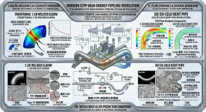
總結而言,在現代調峰型 CCPP 的高能與高危險化學管線設計中,摒棄傳統 1.5D 銲接彎頭,全面轉向具備 IH-PBHT 工法支撐的 3D/5D 冷作彎管,不單純是零組件的替換,而是一場涵蓋 ASME B31J 宏觀力學、微觀冶金學與流體動力學的系統性工程革命,是確保新世代電廠安全、可靠與高經濟效能的必然選擇。In conclusion, in the design of high-energy and high-hazard chemical piping for modern peak-shaving CCPPs, abandoning traditional 1.5D welded elbows and comprehensively pivoting to 3D/5D cold-bent pipes supported by the IH-PBHT method is not merely a component swap. It is a systematic engineering revolution encompassing ASME B31J macro-mechanics, micro-metallurgy, and fluid dynamics, representing the inevitable choice for ensuring the safety, reliability, and high economic efficiency of the next generation of power plants.
參考文獻 / References
- Combined Cycle Power Plants and Renewable Energy Integration, https://drpress.org/ojs/index.php/HSET/article/download/29152/28609/42224
- evaluating the impact of renewable energy integration on the, https://ijssbulletin.com/index.php/IJSSB/article/download/771/952/1676
- Combined Cycle Power Plants (CCPP) – Siemens Energy, https://www.siemens-energy.com/global/en/home/products-services/product/combined-cycle-power-plants.html
- Thermodynamic Analysis of Combined Cycle Power Plant Fired with, https://www.energy-proceedings.org/wp-content/uploads/icae2024/1728014537.pdf
- Components of Cycling – CCPP – Siemens | PDF – Scribd, https://www.scribd.com/doc/290928956/Components-of-Cycling-CCPP-Siemens
- Combined Cycle Power Plants: A comparison between two different, https://www.researchgate.net/publication/263372280_Combined_Cycle_Power_Plants_A_comparison_between_two_different_dynamic_models_to_evaluate_transient_behaviour_and_residual_life
- HRSGs for Next Generation Combined Cycle Plants, https://www.power-eng.com/gas/combined-cycle/hrsgs-for-next-generation-combined-cycle-plants/
- 基於2026 ASME B31J 規範之P9x 高壓蒸汽管線洩水坡度設計與5D, https://yz-pipe-bending.com.tw/%E5%9F%BA%E6%96%BC-2026-asme-b31j-%E8%A6%8F%E7%AF%84%E4%B9%8B-p9x-%E9%AB%98%E5%A3%93%E8%92%B8%E6%B1%BD%E7%AE%A1%E7%B7%9A%E6%B4%A9%E6%B0%B4%E5%9D%A1%E5%BA%A6%E8%A8%AD%E8%A8%88%E8%88%87-1-5d-%E5%B0%8D/
- 技術分析報告:GE 最先進7HA 級燃氣渦輪機與潁璋工程Cold, https://yz-pipe-bending.com.tw/%E6%8A%80%E8%A1%93%E5%88%86%E6%9E%90%E5%A0%B1%E5%91%8A%EF%BC%9Age-%E6%9C%80%E5%85%88%E9%80%B2-7ha-%E7%B4%9A%E7%87%83%E6%B0%A3%E6%B8%A6%E8%BC%AA%E6%A9%9F%E8%88%87%E6%BD%81%E7%92%8B%E5%B7%A5%E7%A8%8B-co/
- 基於ASME B31J 柔性分析之P5/P11/P22 中高溫管線潛變壽命預測暨, https://yz-pipe-bending.com.tw/%E5%9F%BA%E6%96%BC-asme-b31j-%E6%9F%94%E6%80%A7%E5%88%86%E6%9E%90%E4%B9%8B-p5-p11-p22-%E4%B8%AD%E9%AB%98%E6%BA%AB%E7%AE%A1%E7%B7%9A%E6%BD%9B%E8%AE%8A%E5%A3%BD%E5%91%BD%E9%A0%90%E6%B8%AC%E6%9A%A8/
- SCR CATALYST MANAGEMENT – Combined Cycle Journal, https://www.ccj-online.com/scr-catalyst-management/
- Basic ccpp overview Power plant | PPT – Slideshare, https://www.slideshare.net/slideshow/basic-ccpp-overview-power-plant/25023756
- Ammonia Stress Corrosion Cracking – Inspectioneering, https://inspectioneering.com/tag/ammonia+stress+corrosion+cracking
- A Guide to Amine Stress Corrosion Cracking in Oil & Gas Processing, https://integratedglobal.com/en/insights/amine-stress-corrosion-cracking-in-refinery-regeneration-unit/
- 99 Diseases of Pressure Equipment: Amine Cracking, https://inspectioneering.com/journal/2005-01-01/3478/99-diseases-of-pressure-equipm
- Chapter 17 — Special Requirements – imorules, https://www.imorules.com/GUID-DF70AEB7-B5E8-4BE8-ABAD-5F9AB37A7BD9.html
- 結合最新ASME B31J 規範之高壓蒸汽管線非標準洩水坡度設計下的銲, https://yz-pipe-bending.com.tw/%E7%B5%90%E5%90%88%E6%9C%80%E6%96%B0-asme-b31j-%E8%A6%8F%E7%AF%84%E4%B9%8B%E9%AB%98%E5%A3%93%E8%92%B8%E6%B1%BD%E7%AE%A1%E7%B7%9A%E9%9D%9E%E6%A8%99%E6%BA%96%E6%B4%A9%E6%B0%B4%E5%9D%A1%E5%BA%A6%E8%A8%AD/
- Piping Elbow or Bend SIF (Stress Intensification Factor), https://whatispiping.com/bend-sif/
- Understanding SIF for Piping Elbows | PDF | Stress (Mechanics), https://www.scribd.com/document/961304255/Pipe-ELbow-SIF
- Piping Design Training for Power Plants | PDF – Scribd, https://www.scribd.com/document/355053988/02-Piping-Training-Materail-PAD
- ANSI/ASME B31.1, “Power Piping” American National Standard, https://www.nrc.gov/docs/ML0314/ML031470592.pdf
- 基於2026 ASME B31J 規範之P9x 高壓蒸汽管線設計與工法解析, https://yz-pipe-bending.com.tw/%E5%9F%BA%E6%96%BC-2026-asme-b31j-%E8%A6%8F%E7%AF%84%E4%B9%8B-p9x-%E9%AB%98%E5%A3%93%E8%92%B8%E6%B1%BD%E7%AE%A1%E7%B7%9A%E8%A8%AD%E8%A8%88%E8%88%87%E5%B7%A5%E6%B3%95%E8%A7%A3%E6%9E%90%EF%BC%9A/
- unknown_url
- CCPP 高壓蒸汽管線抗動態負荷之最佳化設計:冷作彎管工法與管線, https://yz-pipe-bending.com.tw/ccpp-%E9%AB%98%E5%A3%93%E8%92%B8%E6%B1%BD%E7%AE%A1%E7%B7%9A%E6%8A%97%E5%8B%95%E6%85%8B%E8%B2%A0%E8%8D%B7%E4%B9%8B%E6%9C%80%E4%BD%B3%E5%8C%96%E8%A8%AD%E8%A8%88%EF%BC%9A%E5%86%B7%E4%BD%9C%E5%BD%8E/
- CCPP電廠P9x高能管線曲率半徑(5D規格品銲接彎頭與3D/5D冷作, https://yz-pipe-bending.com.tw/ccpp%E9%9B%BB%E5%BB%A0p9x%E9%AB%98%E8%83%BD%E7%AE%A1%E7%B7%9A%E6%9B%B2%E7%8E%87%E5%8D%8A%E5%BE%91%EF%BC%881-5d%E8%A6%8F%E6%A0%BC%E5%93%81%E9%8A%B2%E6%8E%A5%E5%BD%8E%E9%A0%AD%E8%88%873d-5d%E5%86%B7/
- CCPP 系統中濕蒸氣之沖蝕行為預測與管件防護優化研究(Research, https://yz-pipe-bending.com.tw/ccpp-%E7%B3%BB%E7%B5%B1%E4%B8%AD%E6%BF%95%E8%92%B8%E6%B0%A3%E4%B9%8B%E6%B2%96%E8%9D%95%E8%A1%8C%E7%82%BA%E9%A0%90%E6%B8%AC%E8%88%87%E7%AE%A1%E4%BB%B6%E9%98%B2%E8%AD%B7%E5%84%AA%E5%8C%96%E7%A0%94/
- 動力管線冷作彎管之真圓度與壁厚減薄對ASME B31J 應力係數之影響, https://yz-pipe-bending.com.tw/%E5%8B%95%E5%8A%9B%E7%AE%A1%E7%B7%9A%E5%86%B7%E4%BD%9C%E5%BD%8E%E7%AE%A1%E4%B9%8B%E7%9C%9F%E5%9C%93%E5%BA%A6%E8%88%87%E5%A3%81%E5%8E%9A%E6%B8%9B%E8%96%84%E5%B0%8D-asme-b31j-%E6%87%89%E5%8A%9B%E4%BF%82/
- 針對P92 與316LN 在3D/5D 冷作彎管後之消除應力熱處理(PBHT, https://yz-pipe-bending.com.tw/%E9%87%9D%E5%B0%8D-p92-%E8%88%87-316ln-%E5%9C%A8-3d-5d-%E5%86%B7%E4%BD%9C%E5%BD%8E%E7%AE%A1%E5%BE%8C%E4%B9%8B%E6%B6%88%E9%99%A4%E6%87%89%E5%8A%9B%E7%86%B1%E8%99%95%E7%90%86-pbht-%E6%A9%9F%E5%88%B6/
- Piping Classification for Power Station | PDF – Scribd, https://www.scribd.com/document/652002264/Calik-Spec
- How to manage stress corrosion cracking in new ammonia vessels, https://blog.technicalsafetybc.ca/how-manage-stress-corrosion-cracking-new-ammonia-vessels
- Mastering ASME B31J Piping Stress Analysis for Plant Integrity, https://epcland.com/asme-b31j-piping-stress-analysis/
- Importance & Impact of Stress Intensification Factor (SIF) in Piping, https://whatispiping.com/stress-intensification-factor-sif/
- ASME B31.3 Stress Range Factor: The 2022 Revision and Why It, https://blog.vibrationdata.com/2026/07/18/asme-b31-3-piping-fatigue/
- Stress Intensity Factor (SIF), Flexibility Factor: ASME B31.3 vs ASME, https://whatispiping.com/stress-intensity-factor-sif-flexibility-factor-asme-b-31j/
- Stress intensification factor, sustained stress index and flexibility, https://www.researchgate.net/publication/343479473_Stress_intensification_factor_sustained_stress_index_and_flexibility_factor_analysis_of_large_DT_elbows
- Introduction to ASME B31J Standard – Northern Crescent Inc., https://www.northerncrescent.ca/blog/introduction-to-asme-b31j-standard/
- B31J, https://sites.google.com/site/fareastpiperreference/asme/b31j
- ASME B31J-2023 Overview: Stress Intensification Factor (SIF) and, https://fengshecad.com/795/
- SIF & Flexibility Factors — ASME B31J-2023 & NM.1 HDPE, https://pipingtoolset.com/tools/sif-flexibility-factors/
- Stress Intensification Factors (SIFs) in Pipe Stress Analysis, https://simumech.com/stress-intensification-factors-sifs-in-pipe-stress-analysis/
- Sustained Stress Indices (SSI) in The B31.3 2010 Edition – Scribd, https://www.scribd.com/document/372066988/Sustained-Stress-Indices-SSI-in-the-B31-3-2010-Edition
- ASME B31J (2023) Stress Intensification Factors, https://docs.bentley.com/LiveContent/web/AutoPIPE-v2026/Help/en/Topics/Codes/ASME_B31J_2023_Stress_Intensification_Factors.html
- Low Cycle Fatigue, https://fatigue-life.com/low-cycle-fatigue/
- Approaches to Technology of Thermal Fatigue Life Prediction of, https://www.denso-ten.com/business/technicaljournal/pdf/33note2.pdf
- The Coffin-Manson Model | Bohrium, https://www.bohrium.com/en/sciencepedia/feynman/keyword/coffin_manson_model
- Low-Cycle Thermal Fatigue – NASA Technical Reports Server, https://ntrs.nasa.gov/api/citations/19860017179/downloads/19860017179.pdf
- 3 branch stress own-goal – Stress and Integrity, https://stressandintegrity.com/b31-3-2016-stress-issue/
- Ammonia Stress Corrosion Cracking Overview | PDF – Scribd, https://www.scribd.com/document/458729926/pearson2008-pdf
- Stress Corrosion Cracking (SCC), https://irc.wisc.edu/export.php?ID=221
- Stress corrosion cracking of steels in liquid ammonia – ResearchGate, https://www.researchgate.net/publication/390386276_Stress_corrosion_cracking_of_steels_in_liquid_ammonia_A_comprehensive_literature_review
- API RP 945 Reballot – PDFCOFFEE.COM, https://pdfcoffee.com/api-rp-945-reballot-pdf-free.html
- Welding Tee SIF Calculator — ASME B31.3 Appendix D / B31J, https://pipingtoolset.com/calculators/welding-tee-sif/
- 基於ASME B31.3 規範之高黏度流體輸送管線研究:5D CNC 冷作彎, https://yz-pipe-bending.com.tw/%E5%9F%BA%E6%96%BC-asme-b31-3-%E8%A6%8F%E7%AF%84%E4%B9%8B%E9%AB%98%E9%BB%8F%E5%BA%A6%E6%B5%81%E9%AB%94%E8%BC%B8%E9%80%81%E7%AE%A1%E7%B7%9A%E7%A0%94%E7%A9%B6%EF%BC%9A5d-cnc-%E5%86%B7%E4%BD%9C%E5%BD%8E/
- Refining Equipment Damage Mechanisms: API 571 Guide, https://studylib.net/doc/25883176/api-571–2020-
- 基於ASME B31J 柔性分析與多軸損傷動力學之316N 高溫管線潛變, https://yz-pipe-bending.com.tw/%E5%9F%BA%E6%96%BC-asme-b31j-%E6%9F%94%E6%80%A7%E5%88%86%E6%9E%90%E8%88%87%E5%A4%9A%E8%BB%B8%E6%90%8D%E5%82%B7%E5%8B%95%E5%8A%9B%E5%AD%B8%E4%B9%8B-316n-%E9%AB%98%E6%BA%AB%E7%AE%A1%E7%B7%9A%E6%BD%9B/