
一、導論與先進高溫管線之產業背景 / I. Introduction and Industrial Background of Advanced High-Temperature Piping
隨著全球能源轉型的急遽推進,現代化燃氣複循環電廠 (Combined Cycle Power Plant, CCPP) 在電力系統中扮演著提供基載與快速調度之雙重關鍵角色。為追求極致的熱力學循環效率,新世代氣渦輪機系統(如 GE 7HA.03 等 H 級先進機組)的運轉參數不斷向上攀升,帶動熱回收爐 (Heat Recovery Steam Generator, HRSG) 及其主蒸汽管線與熱重熱管線 (Hot Reheat Piping) 進入超臨界甚至是極超臨界之嚴苛狀態1。此類高能高壓管線 (High Energy Piping, HEP) 在服役過程中,不僅需承受高達 600°C 至 650°C 的高溫與超過 25 MPa 的內部蒸汽壓力,更因應電網需求面臨極高的動態升降載率(可達 75 MW/min)與頻繁的啟停循環,致使管線長期處於極端之「潛變-疲勞交互作用 (Creep-Fatigue Interaction)」環境下1。 With the rapid advancement of the global energy transition, modern Combined Cycle Power Plants (CCPP) play a dual critical role in providing base load and rapid dispatch capabilities in the power grid. To achieve ultimate thermodynamic cycle efficiency, the operating parameters of new-generation gas turbine systems (such as GE 7HA.03 and other H-class advanced units) continue to escalate, driving Heat Recovery Steam Generators (HRSG) and their main steam and hot reheat piping into supercritical or even ultra-supercritical conditions1. During service, such High Energy Piping (HEP) must not only withstand high temperatures of 600°C to 650°C and internal steam pressures exceeding 25 MPa but also endure extreme dynamic ramp rates (up to 75 MW/min) and frequent start-stop cycles due to grid demands. This places the piping in an extreme environment of “Creep-Fatigue Interaction” over the long term1.
為應對此一極端應力狀態,傳統的低合金鉻鉬鋼 (如 P22) 已無法滿足設計需求。自 1970 年代起,美國橡樹嶺國家實驗室 (ORNL) 開發出改質 9Cr-1Mo 鋼,透過微調釩 (V)、鈮 (Nb) 與氮 (N) 的比例,大幅提升了高溫潛變強度,促成了 ASME Grade 91 (P91) 鋼的廣泛應用3。隨後,日本東京大學等機構於 1980 年代中後期進一步研發出以鎢 (W) 取代部分鉬 (Mo) 並添加硼 (B) 的新型鋼種,最終被納入規範成為 Grade 92 (P92) 鋼3。這類被統稱為潛變強度強化鐵素體鋼 (Creep Strength Enhanced Ferritic Steels, CSEF) 的材料,雖然在母材狀態下具備卓越的抗高溫潛變性能,但其銲道區域(特別是熱影響區,HAZ)在經歷銲接熱循環與後續長期服役後,極易發生不可逆的微觀組織退化。此種退化不僅嚴重削弱材料的潛變壽命,更頻繁引發無預警的第四型潛變破裂 (Type IV Cracking)6。 To cope with these extreme stress conditions, traditional low-alloy chrome-molybdenum steels (such as P22) can no longer meet design requirements. Since the 1970s, the Oak Ridge National Laboratory (ORNL) in the U.S. developed a modified 9Cr-1Mo steel. By fine-tuning the proportions of vanadium (V), niobium (Nb), and nitrogen (N), its high-temperature creep strength was significantly enhanced, leading to the widespread application of ASME Grade 91 (P91) steel3. Subsequently, in the mid-to-late 1980s, institutions like the University of Tokyo in Japan further developed a new steel grade by replacing part of the molybdenum (Mo) with tungsten (W) and adding boron (B), which was ultimately standardized as Grade 92 (P92) steel3. Collectively known as Creep Strength Enhanced Ferritic (CSEF) steels, these materials possess excellent high-temperature creep resistance in their base metal state. However, their weld zones—particularly the Heat-Affected Zone (HAZ)—are highly susceptible to irreversible microstructural degradation after undergoing welding thermal cycles and subsequent long-term service. This degradation not only severely impairs the material’s creep life but also frequently triggers unpredictable Type IV creep cracking6.
本報告旨在針對 CCPP 電廠 P9x 級高能高壓管線,進行全面且深度的物理冶金與工程實務探討。為構築完整的資產完整性管理藍圖,本文將從微觀的合金設計與劣化機制出發,過渡至巨觀的法規標準演進,並最終落實於業主營運決策、EPC 設計考量以及現場施作廠商之因應策略。
This report aims to conduct a comprehensive and in-depth exploration of the physical metallurgy and engineering practices of P9x class high-energy, high-pressure piping in CCPP power plants. To construct a complete blueprint for asset integrity management, this paper will start from microscopic alloy design and degradation mechanisms, transition to the macro-evolution of regulatory standards, and ultimately address owner operational decisions, EPC design considerations, and response strategies for on-site fabrication contractors.
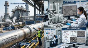
二、P9x 鋼材之物理冶金基礎與強化機制 / II. Physical Metallurgy Foundations and Strengthening Mechanisms of P9x Steels
要理解高能管線在極端環境下的劣化與失效,首先必須回歸 P9x 系列鋼材的合金設計本質。To understand the degradation and failure of high-energy piping in extreme environments, one must first return to the fundamental alloy design of the P9x series steels.
2.1 化學成分演進與微觀結構設計 / 2.1 Evolution of Chemical Composition and Microstructural Design
P91 與 P92 均屬於 9% 鉻系馬氏體耐熱鋼,其卓越的高溫機械性質並非偶然,而是基於極為精密的合金成分調控與熱處理工法。基礎的 P91 鋼含有約 9% 的鉻以提供抗高溫蒸汽氧化能力,並利用約 1% 的鉬提供固溶強化,同時藉由釩、鈮與氮的微量添加,形成穩定的納米級析出物3。為進一步突破極限,P92 鋼在此基礎上進行了革命性的調整,將鉬含量降低至約 0.5%,並加入高達 1.8% 的鎢,同時微量添加硼元素。由於鎢原子半徑較大,在高溫下具有更低的擴散係數,能提供更持久的固溶強化效應;而硼則能偏析於原奧氏體晶界 (Prior Austenite Grain Boundaries, PAGB),穩定晶界上的碳化物,顯著延緩微觀組織的回覆與軟化10。歐洲潛變合作委員會 (ECCC) 的資料庫顯示,P92 鋼在 600°C 下的十萬小時潛變破斷強度約為 113 MPa,相較於 P91 的 90 MPa 顯著提升了約 25% 至 30%12。 Both P91 and P92 belong to the 9% chromium martensitic heat-resistant steels. Their exceptional high-temperature mechanical properties are not accidental but are based on highly precise alloy composition adjustments and heat treatment methods. The foundational P91 steel contains about 9% chromium to provide high-temperature steam oxidation resistance and utilizes about 1% molybdenum for solid solution strengthening. Meanwhile, trace additions of vanadium, niobium, and nitrogen form stable nano-scale precipitates3. To further push the limits, P92 steel underwent revolutionary adjustments by reducing the molybdenum content to about 0.5%, adding up to 1.8% tungsten, and introducing a trace amount of boron. Because the tungsten atom has a larger radius, it exhibits a lower diffusion coefficient at high temperatures, providing a more enduring solid solution strengthening effect. Boron segregates at Prior Austenite Grain Boundaries (PAGB), stabilizing the carbides on the boundaries and significantly delaying microstructural recovery and softening10. The database from the European Creep Collaborative Committee (ECCC) shows that the 100,000-hour creep rupture strength of P92 steel at 600°C is approximately 113 MPa, a significant 25% to 30% increase compared to 90 MPa for P9112.
| 合金元素 / Element (wt.%) | P91 (X10CrMoVNb9-1) | P92 (X10CrWMoVNb9-2) | 冶金機制與物理功能說明 / Metallurgical Mechanism & Physical Function |
| C (碳/Carbon) | 0.08 – 0.12 | 0.07 – 0.13 | 形成各類碳化物,提供析出強化與晶界釘紮。/ Forms various carbides, providing precipitation strengthening and grain boundary pinning. |
| Cr (鉻/Chromium) | 8.00 – 9.50 | 8.50 – 9.50 | 提供高溫抗氧化性,為形成M23C6 之主要元素。/ Provides high-temperature oxidation resistance; main element for forming M23C6 . |
| Mo (鉬/Moly) | 0.85 – 1.05 | 0.30 – 0.60 | 固溶強化效應,並抑制雜質元素引發之回火脆性。/ Solid solution strengthening effect; suppresses temper embrittlement caused by impurities. |
| W (鎢/Tungsten) | – | 1.50 – 2.00 | P92 之核心元素,提供強效高溫固溶強化,減緩碳化物粗化速率。/ Core element of P92; provides strong high-temp solid solution strengthening and slows carbide coarsening. |
| V (釩/Vanadium) | 0.18 – 0.25 | 0.15 – 0.25 | 形成納米級 MX 碳氮化物,阻礙差排運動。/ Forms nano-scale MX carbonitrides to hinder dislocation movement. |
| Nb (鈮/Niobium) | 0.06 – 0.10 | 0.04 – 0.09 | 形成高穩定性之 MX 碳氮化物,高溫下不易溶解。/ Forms highly stable MX carbonitrides that resist dissolution at high temperatures. |
| B (硼/Boron) | – | 0.001 – 0.006 | 偏析於晶界,抑制晶界滑移,並穩定 M23C6。/ Segregates at grain boundaries, inhibits sliding, and stabilizes M23C6. |
| N (氮/Nitrogen) | 0.03 – 0.07 | 0.03 – 0.07 | 與釩、鈮結合形成 MX;P92 需控制上限以避免粗大氮化硼。/ Combines with V/Nb to form MX; upper limits in P92 prevent coarse boron nitrides. |
| Al (鋁/Aluminum) | ≦0.04 | ≦0.04 | 若殘留過高會促使軟弱的殘留 δ-肥粒鐵生成,大幅降低潛變抗力。/ Excessive residue promotes weak δ-ferrite formation, drastically reducing creep resistance. |
(表 1:P91 與 P92 鋼之化學成分與冶金機制對照 / Table 1: Chemical Composition and Metallurgical Mechanisms of P91 and P92 Steels) [cite: 4, 15, 16, 17]
除了上述有益元素外,不純物元素的控制亦極為關鍵。研究指出,若銲道金屬中含有過高的鋁 (Al),將導致在凝固過程中形成軟弱的殘留 δ-肥粒鐵 (δ-ferrite)。在潛變破裂測試中,高鋁銲道的抗潛變能力會顯著低於低鋁銲道,因為 δ-肥粒鐵較周圍的麻田散鐵基體柔軟,無法有效抵禦高溫應力,極易成為潛變變形的弱點15。 In addition to the beneficial elements mentioned above, the control of impurity elements is also extremely critical. Research indicates that if the weld metal contains excessively high aluminum (Al), it will lead to the formation of weak residual δ-ferrite during solidification. In creep rupture tests, the creep resistance of high-Al welds is significantly lower than that of low-Al welds because δ-ferrite is softer than the surrounding martensitic matrix and cannot effectively withstand high-temperature stress, making it highly susceptible to becoming a weak point for creep deformation15.
2.2 多層次之微觀強化結構 / 2.2 Multi-Layered Microstructural Strengthening Mechanisms
P9x 鋼的初始微觀組織建立於嚴苛的熱處理工序:首先於 1040°C 至 1080°C 進行正常化 (Normalizing),使合金元素完全固溶於奧氏體中;接著以適當速率冷卻,誘發麻田散鐵相變,形成具有極高差排密度的板條狀麻田散鐵 (Lath Martensite)10。隨後於 730°C 至 800°C 區間進行高溫回火 (Tempering),此過程不僅釋放了淬火殘留應力,更促使兩類關鍵析出物均勻形成,建構出強大的多層次強化機制12: 第一種為富含鉻與鐵的 M23C6 碳化物,主要沿著原奧氏體晶界 (PAGB) 以及板條邊界析出。這些碳化物如同鉚釘般,強效發揮「釘紮 (Zener Pinning)」作用,有效抑制高溫下晶界之滑移與次晶粒之異常成長12。 第二種為富含釩與鈮的 MX 型碳氮化物 (例如 V(C,N) 或 Nb(C,N)),其尺寸多在數十納米等級,極為均勻地散佈於板條麻田散鐵內部。由於其熱力學穩定性極高,能有效阻擋差排的高溫攀移 (Climb) 與滑移,為 P9x 鋼提供了最核心的析出強化效應3。 The initial microstructure of P9x steels is established through a rigorous heat treatment process: first, normalizing is performed at 1040°C to 1080°C to fully dissolve alloy elements into austenite; then, cooling at an appropriate rate induces a martensitic phase transformation, forming lath martensite with an extremely high dislocation density10. Subsequently, high-temperature tempering is conducted in the 730°C to 800°C range. This process not only relieves quenching residual stresses but also promotes the uniform formation of two key types of precipitates, building a powerful multi-layered strengthening mechanism12: The first type consists of chromium- and iron-rich M23C6 carbides, which precipitate primarily along Prior Austenite Grain Boundaries (PAGB) and lath boundaries. Acting like rivets, these carbides strongly exert a “Zener Pinning” effect, effectively inhibiting grain boundary sliding and abnormal sub-grain growth at high temperatures12. The second type includes vanadium- and niobium-rich MX-type carbonitrides (e.g., V(C,N) or Nb(C,N)), which are mostly tens of nanometers in size and evenly distributed within the martensite laths. Due to their extremely high thermodynamic stability, they effectively block high-temperature dislocation climb and glide, providing P9x steels with their core precipitation strengthening effect3.
三、長期高溫服役下之微觀劣化與相變機制 / III. Microstructural Degradation and Phase Transformation Mechanisms Under Long-Term High-Temperature Service
儘管 P9x 鋼在出廠時具備優異的微觀組織,但在 600°C 以上高溫與持續潛變應力的長期疊加作用下,材料內部的熱力學平衡將逐漸被打破。這些隨時間演進的微觀相變與粗化機制,正是推動宏觀力學性質衰退、決定高能管線剩餘壽命的底層邏輯。Although P9x steels possess an excellent microstructure straight from the factory, the thermodynamic equilibrium within the material is gradually broken down under the prolonged superimposed effects of high temperatures above 600°C and continuous creep stress. These time-evolving microstructural phase transformations and coarsening mechanisms are the fundamental logic driving the decline of macroscopic mechanical properties and determining the remaining life of high-energy piping.
3.1 M23C6 碳化物的粗化與基體回覆 / 3.1 Coarsening of M23C6 Carbides and Matrix Recovery
隨著服役時間的推進,原本負責釘紮邊界的 M23C6 碳化物會因奧斯華熟化機制 (Ostwald Ripening) 而逐漸粗化。研究觀察指出,在經歷 100,000 小時的 600°C 熱暴露後,M23C6 顆粒的等效直徑可長至超過 100 至 200 納米13。當這些碳化物不斷長大而數量密度銳減時,對板條邊界的釘紮力隨之下降,導致板條麻田散鐵發生明顯的回覆現象 (Recovery)。板條結構逐漸寬化、合併,內部的差排網絡消散,最終退化為多邊形化的等軸肥粒鐵結構,使材料完全喪失阻礙塑性變形的能力10。 As service time progresses, the M23C6 carbides originally responsible for pinning boundaries will gradually coarsen due to the Ostwald ripening mechanism. Research observations indicate that after 100,000 hours of thermal exposure at 600°C, the equivalent diameter of M23C6 particles can grow to exceed 100 to 200 nanometers13. When these carbides continuously grow while their number density sharply declines, their pinning force on lath boundaries decreases, causing the lath martensite to undergo significant recovery. The lath structures gradually widen and merge, the internal dislocation network dissipates, and they eventually degrade into a polygonized equiaxed ferrite structure, causing the material to completely lose its ability to hinder plastic deformation10.
3.2 拉維斯相 (Laves Phase) 之析出動態 / 3.2 Precipitation Dynamics of Laves Phase
特別在 P92 鋼中,拉維斯相 (Laves Phase,主要形式為 Fe2W或Fe2Mo) 的生成與演化是決定其長期潛變壽命的最大變數18。Laves 相在 700°C 以下的高溫服役初期會迅速成核析出,短暫提供顆粒強化效應。然而,其粗化速率極快,遠超過 M23C6。當 Laves 相大量析出並粗化時,將產生雙重破壞效應:首先,它會大量消耗基體中的鎢與鉬,導致原本強效的固溶強化效應急劇降低(固溶枯竭,Solid Solution Depletion);其次,粗大且硬脆的 Laves 相顆粒(在極端老化案例中,聚集尺寸甚至可達 3.4 μm)會在其與基體的交界面上產生嚴重的應力集中,成為潛變空孔 (Creep Cavities) 優先成核的最佳位置20。臨床研究顯示,過大的 Laves 相聚集甚至會使原奧氏體晶界掙脫釘紮,引發微裂紋的快速拓展20。 Particularly in P92 steel, the formation and evolution of the Laves phase (primarily in the form of Fe2W or Fe2Mo) is the greatest variable determining its long-term creep life18. During the early stages of high-temperature service below 700°C, the Laves phase rapidly nucleates and precipitates, briefly providing a particle strengthening effect. However, its coarsening rate is exceedingly fast, far exceeding that of M23C6. When the Laves phase precipitates heavily and coarsens, it generates a dual destructive effect: first, it consumes a large amount of tungsten and molybdenum from the matrix, causing the originally potent solid solution strengthening effect to drop sharply (Solid Solution Depletion); second, coarse and brittle Laves phase particles (which can aggregate to sizes approaching 3.4 μm in extreme aging cases) create severe stress concentrations at their interfaces with the matrix, becoming prime sites for the preferential nucleation of creep cavities20. Clinical studies show that oversized Laves phase aggregates can even cause prior austenite grain boundaries to break free from pinning, triggering the rapid propagation of microcracks20.
3.3 改質 Z相 (Modified Z-phase) 的毀滅性形成 / 3.3 The Destructive Formation of Modified Z-phase
除了 Laves 相的威脅外,Z相 (Cr(V,Nb)N) 的形成更被視為 9-12% 鉻系鋼中具毀滅性的劣化機制13。Z相的形成通常伴隨較長的孕育期(多在服役數萬小時後才明顯可見),其生長過程實則是一個吞噬 MX 碳氮化物的過程。研究指出,Z相主要透過從基體中吸收鉻原子,在原有的富釩、富鈮 MX 顆粒上形成介穩態的混合型 MX/Z 顆粒,最終完全轉變為粗大的 Z相10。 In addition to the threat of the Laves phase, the formation of the Z-phase (Cr(V,Nb)N) is considered a highly destructive degradation mechanism in 9-12% chromium steels13. The formation of the Z-phase is typically accompanied by a long incubation period (usually only noticeable after tens of thousands of hours in service), and its growth process is essentially one that consumes MX carbonitrides. Research indicates that the Z-phase primarily absorbs chromium atoms from the matrix to form metastable hybrid MX/Z particles on the original vanadium- and niobium-rich MX particles, ultimately transforming completely into the coarse Z-phase10.
由於 Z相顆粒的生長極不受控,其尺寸最終遠大於初始的 MX 析出物,這導致基體內原本密布的納米級 MX 顆粒溶解消失,差排釘紮效應徹底瓦解。熱力學模擬證實,鉻含量是驅動 Z相形成的最主要熱力學動力,這解釋了為何 12% 鉻系耐熱鋼(如 P122)極易遭受快速且大量的 Z相析出,導致潛變強度斷崖式下降;而 P91 與 P92 鋼因鉻含量被精確控制在 9% 左右,Z相的形成速率相對緩慢許多,從而賦予了較佳的長期結構穩定性13。 Because the growth of Z-phase particles is highly uncontrolled, their final size is vastly larger than the initial MX precipitates. This causes the originally densely distributed nano-scale MX particles in the matrix to dissolve and disappear, completely destroying the dislocation pinning effect. Thermodynamic simulations confirm that chromium content is the primary thermodynamic driving force for Z-phase formation. This explains why 12% Cr heat-resistant steels (e.g., P122) are highly susceptible to the rapid and massive precipitation of Z-phase, leading to a cliff-like drop in creep strength. Conversely, because the chromium content in P91 and P92 steels is precisely controlled at around 9%, the formation rate of the Z-phase is comparatively much slower, thereby conferring better long-term structural stability13.
四、銲接熱循環與潛變破裂型態分析 (Type I ~ IV) / IV. Welding Thermal Cycles and Creep Cracking Morphology Analysis (Type I ~ IV)
上述的冶金退化在單純的母材中尚屬緩慢,但一旦遭遇管線製造與組裝中最核心的「銲接」工法,情況便急轉直下。銲接過程產生的極端溫度梯度,徹底破壞了 P9x 鋼母材原先精心調控的微觀組織,並在銲道與熱影響區 (HAZ) 形成了極不均勻的力學與冶金性質分佈22。根據失效發生位置的微觀特徵,銲道區域的潛變破裂可被嚴格劃分為四種主要型態,其中以第四型破裂 (Type IV) 最具破壞性與隱蔽性8。 The metallurgical degradation described above is relatively slow in the pure base metal, but the situation deteriorates rapidly once it encounters “welding,” the core fabrication method in piping manufacturing and assembly. The extreme temperature gradients generated during welding completely destroy the carefully controlled initial microstructure of the P9x base metal, forming highly uneven mechanical and metallurgical property distributions in the weld and Heat-Affected Zone (HAZ)22. Based on the microstructural characteristics of the failure locations, creep cracking in the weld zone can be strictly classified into four main types, among which Type IV cracking is the most destructive and insidious8.
4.1 破裂型態之分類與微觀特徵 / 4.1 Classification and Microstructural Characteristics of Cracking Types
- Type I 破裂 (Type I Cracking):這類裂紋起源且完全侷限於銲道金屬 (Weld Metal, WM) 內部。常見於凝固過程中的熱裂紋,或是銲道金屬本身高溫潛變抗力不足所引發的巨觀破裂3。/ These cracks originate and remain entirely within the weld metal (WM). They are commonly seen as hot cracks during solidification or as macroscopic ruptures caused by insufficient high-temperature creep resistance of the weld metal itself3.
- Type II 破裂 (Type II Cracking):裂紋同樣起源於銲道金屬,但會向外延伸,穿過熔合線 (Fusion Line) 並擴展至熱影響區或母材中。這通常與銲道材料的破壞韌性較差以及複雜的三維殘留應力場有關7。/ The cracks also originate in the weld metal but extend outward, crossing the fusion line and propagating into the HAZ or base metal. This is typically associated with poor fracture toughness of the weld material and complex three-dimensional residual stress fields7.
- Type III 破裂 (Type III Cracking):主要發生在緊鄰熔合線的粗晶熱影響區 (Coarse-Grained HAZ, CGHAZ)。此區域在銲接時經歷接近熔點的極高溫,晶粒嚴重粗化,導致晶界脆化。Type III 破裂常與再熱裂紋 (Reheat Cracking) 相關7。在異種金屬銲接 (DMW) 中,緊貼熔合線發生的碳遷移導致的脆性裂紋,有時亦被歸類為 Type IIIa 破裂6。/ This primarily occurs in the Coarse-Grained HAZ (CGHAZ) adjacent to the fusion line. This region experiences extremely high temperatures near the melting point during welding, causing severe grain coarsening and grain boundary embrittlement. Type III cracking is often related to reheat cracking7. In Dissimilar Metal Welds (DMW), brittle cracking caused by carbon migration adjacent to the fusion line is sometimes classified as Type IIIa cracking6.
- Type IV 破裂 (Type IV Cracking / 第四型潛變破裂):專指發生在細晶熱影響區 (Fine-Grained HAZ, FGHAZ) 與間臨界熱影響區 (Intercritical HAZ, ICHAZ) 的提早失效現象。這是一種長期的低應力潛變破裂,為目前 P9x 鋼管線最常見且致命的失效模式12。/ This specifically refers to the premature failure occurring in the Fine-Grained HAZ (FGHAZ) and Intercritical HAZ (ICHAZ). It is a long-term, low-stress creep rupture and is currently the most common and fatal failure mode for P9x steel piping12.
4.2 Type IV 破裂的物理冶金學解析 / 4.2 Physical Metallurgy Analysis of Type IV Cracking
Type IV 破裂的本質,在於銲接熱循環對該區域相變的災難性干擾。在銲接過程中,ICHAZ 所經歷的峰值溫度 (Tp) 剛好落於下臨界溫度 (AC1) 與上臨界溫度 (AC3) 之間8。以 P91 鋼為例,AC1 約為 800°C 至 830°C,而 AC3 約為 890°C 至 940°C(因鎢的穩定作用,P92 的相應溫度略有不同)28。在這個溫度區間,基體僅發生部分的沃斯田鐵相變,導致原始的 M23C6 與 MX 析出物部分溶解並粗化,徹底失去了對次晶界的釘紮能力1。 The essence of Type IV cracking lies in the disastrous interference of welding thermal cycles with phase transformations in this region. During welding, the peak temperature (Tp) experienced by the ICHAZ falls exactly between the lower critical temperature (AC1) and the upper critical temperature (AC3)8. For example, in P91 steel, AC1 is approximately 800°C to 830°C, and AC3 is around 890°C to 940°C (the corresponding temperatures for P92 are slightly different due to the stabilizing effect of tungsten)28. In this temperature range, the matrix undergoes only partial austenitic transformation, causing the original M23C6 and MX precipitates to partially dissolve and coarsen, completely losing their ability to pin sub-grain boundaries1.
相鄰的 FGHAZ 經歷的峰值溫度略高於AC3,使基體完全轉變為沃斯田鐵,但由於升溫與降溫的駐留時間極短,晶粒無法長大,在冷卻後形成了極其細小的高差排密度麻田散鐵6。這使得 FGHAZ 擁有了過度密集的晶界。 The adjacent FGHAZ experiences a peak temperature slightly above AC3, allowing the matrix to fully transform into austenite. However, due to the extremely short dwell time during heating and cooling, the grains cannot grow, forming extremely fine lath martensite with high dislocation density upon cooling6. This endows the FGHAZ with an overly dense network of grain boundaries.
在隨後的銲後熱處理 (PWHT) 乃至於高溫服役期間,這些未完全固溶的碳化物會以異常的速率重新析出並粗化,而密集的晶界又提供了大量的擴散路徑,進一步加速了粗化過程。最終,FGHAZ 與 ICHAZ 區域演變成一個缺乏析出強化的「極度軟化帶 (Soft Zone)」22。在管線服役受壓時,這個微觀軟化帶被兩側較強的銲道金屬與母材所夾持,於橫向載荷下產生了極高的三維拘束應力 (Triaxial Stress Constraint)22。應變被迫高度集中於此狹窄區域,促使潛變空孔快速成核、長大並互相連結成巨觀裂紋,最終導致管線在遠低於設計壽命(有時僅數萬小時)時即發生災難性的斷裂1。 During subsequent Post-Weld Heat Treatment (PWHT) and high-temperature service, these incompletely dissolved carbides re-precipitate and coarsen at an abnormal rate, while the dense grain boundaries provide abundant diffusion paths, further accelerating the coarsening process. Ultimately, the FGHAZ and ICHAZ regions evolve into a severely “Soft Zone” lacking precipitation strengthening22. When the piping is under operational pressure, this microscopic soft zone is clamped between the stronger weld metal and base metal, generating extremely high Triaxial Stress Constraint under transverse loading22. Strain is forced to concentrate highly in this narrow area, promoting the rapid nucleation, growth, and interconnection of creep cavities into macroscopic cracks. This ultimately leads to catastrophic pipe rupture at a fraction of the design life (sometimes within tens of thousands of hours)1.
五、銲後熱處理 (PWHT) 邊界與 ASME B31.1 規範演進 / V. Post-Weld Heat Treatment (PWHT) Boundaries and the Evolution of ASME B31.1 Codes
有鑑於 Type IV 破裂具有高度隱蔽性與致命的風險,銲後熱處理 (PWHT) 成為釋放殘留應力並回火麻田散鐵的必經程序,更是決定管線最終潛變抗力的防線。為此,美國機械工程師學會 (ASME) 在最新的 2025/2026 年版 BPVC Section IX 與 B31.1 動力管線規範中,針對 P-No. 15E (包含 P91 與 P92) 鋼的熱處理參數施加了極其嚴苛的操作邊界1。 Given that Type IV cracking is highly insidious and fatal, Post-Weld Heat Treatment (PWHT) is a mandatory procedure for relieving residual stress and tempering martensite; it is also the final defense determining the pipeline’s ultimate creep resistance. Therefore, in the latest 2025/2026 editions of BPVC Section IX and B31.1 Power Piping codes, the American Society of Mechanical Engineers (ASME) has imposed extremely strict operational boundaries for the heat treatment parameters of P-No. 15E steels (including P91 and P92)1.
5.1 嚴謹的溫度與冷卻率要求 / 5.1 Stringent Temperature and Cooling Rate Requirements
- PWHT 前之完全相變冷卻要求 (Pre-PWHT Complete Phase Transformation Cooling Requirement):銲接完成後,為確保高溫下形成的沃斯田鐵能百分之百相變為麻田散鐵,管線必須冷卻至麻田散鐵完成溫度 (Mf) 以下,方能啟動 PWHT 升溫程序。依據 ASME B31.1 新規,若銲材的合金元素 (Ni + Mn) 總和不大於2%,必須冷卻至 190°C (375°F) 以下;若 (Ni + Mn) 超過 1.2% (此類元素會顯著降低 Mf 溫度),則必須冷卻至 95°C (200°F) 以下方為合格1。若未達此條件即貿然升溫,未相變的殘留沃斯田鐵會在 PWHT 結束後的冷卻階段轉變為未回火的脆性麻田散鐵,導致接頭在常溫下極易發生低韌性龜裂。/ After welding is completed, to ensure that the austenite formed at high temperatures fully transforms into martensite, the piping must be cooled below the martensite finish temperature (Mf) before initiating the PWHT heating process. According to the new ASME B31.1 rules, if the sum of alloy elements (Ni + Mn) in the filler metal is ≦ 1.2% , it must be cooled below 190°C (375°F); if (Ni + Mn) > 1.2% (these elements significantly lower the Mf temperature), it must be cooled below 95°C (200°F)1. If heating commences before meeting this condition, untransformed residual austenite will turn into untempered, brittle martensite during the cooling phase after PWHT, making the joint highly susceptible to low-toughness cracking at room temperature.
- 最高 PWHT 溫度之剛性限制 / AC1 臨界線 (Rigid Limit on Maximum PWHT Temperature / AC1 Critical Line):標準的持溫範圍通常落在 705°C 至 775°C 之間1。然而,新規範強調 PWHT 的實際最高溫度絕不可超過材料(包含母材與銲道金屬)的下臨界溫度 (AC1)1。如果銲材選用不當(如含有過高比例的鎳或錳),其 AC1 可能會降至 750°C 甚至更低。此時若仍依據傳統經驗採用 760°C 進行熱處理,將導致材料發生局部的重新奧氏體化 (Re-austenitization)。臨床事故分析表明,經歷過此類錯誤熱處理的 P91 異常管線,硬度會暴跌至規範下限之下(甚至降至 175 HV 左右,低於規範要求的 185-248 HBW),其馬氏體板條將完全消失並退化為異常肥粒鐵,潛變破裂壽命從十萬小時銳減至不足兩萬小時,縮短達兩個數量級20。/ The standard holding temperature range typically falls between 705°C and 775°C1. However, the new code emphasizes that the actual maximum PWHT temperature must never exceed the lower critical temperature (AC1) of the materials (including both base and weld metals)1. If an inappropriate filler metal is selected (e.g., containing excessively high nickel or manganese), its AC1 may drop to 750°C or even lower. If heat treatment is then conducted at 760°C based on traditional experience, it will cause localized re-austenitization of the material. Clinical failure analyses show that abnormal P91 piping subjected to such erroneous heat treatments will suffer a plummeted hardness below the code minimum (even dropping to around 175 HV, below the required 185-248 HBW); its martensite laths will completely disappear and degrade into abnormal ferrite, slashing the creep rupture life from 100,000 hours to less than 20,000 hours—a reduction of up to two orders of magnitude20.
- 違規之補救措施 (Corrective Actions for Non-Compliance):若 PWHT 過程中溫度超過了銲材的 AC1 但未達 800°C,新規範要求必須將該銲道完全刨除,更換合規銲材後重新銲接並施以合格的 PWHT;若最高溫度不幸超過 800°C,不僅銲道,連同受 PWHT 影響的整段母材熱影響區皆被視為完全毀損,必須全數切除汰換,或送回爐中進行完整的正常化與回火程序 (Renormalize and Temper) 後方得重新使用1。/ If the temperature during PWHT exceeds the AC1 of the filler metal but does not reach 800°C, the new code mandates that the weld must be completely removed, replaced with a compliant filler metal, rewelded, and subjected to a proper PWHT. If the maximum temperature unfortunately exceeds 800°C, not only the weld but the entire section of the base metal HAZ affected by the PWHT is deemed completely ruined; it must be fully cut out and replaced or returned to the furnace for a complete Normalize and Temper process before reuse1.
5.2 銲接工法變數之緊縮 / 5.2 Tightening of Welding Method Variables
在銲接工法方面,ASME BPVC Section IX 表格 QW-250 系列亦新增了「銲珠寬度限制 (Weld Bead Width, QW-410.92)」作為補充必要變數 (Supplementary Essential Variable)1。此規範嚴格限制了大寬度的擺弧銲接 (Weave beads)。主要考量在於,寬擺弧銲接伴隨的高線能量 (Heat Input) 與緩慢的行進速度,會導致熱影響區的寬度大幅度擴張。這不僅使最脆弱的 ICHAZ 軟區面積成倍增加,更會嚴重削弱後續堆疊銲道對底層銲道產生的熱回火效應,從而巨幅提升 Type IV 破裂的發生機率與風險1。 In terms of welding methods, the ASME BPVC Section IX Table QW-250 series has newly introduced “Weld Bead Width (QW-410.92)” as a Supplementary Essential Variable1. This code strictly restricts wide weave beads. The primary consideration is that wide weave welding, accompanied by high linear heat input and slow travel speed, drastically expands the width of the HAZ. This not only multiplies the area of the highly vulnerable ICHAZ soft zone but also severely weakens the thermal tempering effect that subsequent overlapping passes have on underlying passes, thereby massively increasing the probability and risk of Type IV cracking1.
六、異種金屬銲接 (DMW) 之冶金挑戰與 EPRI P87 之突破/ VI. Metallurgical Challenges in Dissimilar Metal Welds (DMW) and the EPRI P87 Breakthrough
除了同質銲接的嚴苛要求外,電廠管線佈局中不可避免的異種金屬過渡接頭更帶來了截然不同的挑戰。在 CCPP 電廠與先進熱回收爐中,為了最佳化材料成本與耐熱性能,經常需要將鐵素體的 P9x 鋼與沃斯田鐵不銹鋼(如 TP347H、316L 甚至鎳基合金)進行異種金屬銲接 (Dissimilar Metal Welds, DMW),這常見於過熱器管排與高壓集管器的連接處9。然而,這類接頭在極端溫壓條件下,面臨著極為嚴峻的冶金與力學考驗。 Beyond the strict requirements for similar-metal welding, the unavoidable dissimilar metal transition joints in power plant piping layouts present entirely different challenges. In CCPP and advanced HRSGs, to optimize material costs and heat resistance, it is often necessary to perform Dissimilar Metal Welds (DMW) joining ferritic P9x steels to austenitic stainless steels (such as TP347H, 316L, or even nickel-based alloys). This is commonly found at connections between superheater tube banks and high-pressure headers9. However, under extreme temperature and pressure conditions, these joints face severe metallurgical and mechanical trials.
6.1 碳遷移效應與熱疲勞撕裂 / 6.1 Carbon Migration Effect and Thermal Fatigue Tearing
DMW 面臨的核心難題,在於兩種材料之間存在著巨大的化學勢梯度與物理性質差異。 首先是碳遷移 (Carbon Migration) 現象:在長期高溫服役或高溫 PWHT 期間,碳原子會受到強烈的熱力學驅動力,從鉻含量較低、碳活度較高的 P9x 鋼側,越過熔合線向高鉻含量的沃斯田鐵側或鎳基銲材側進行擴散8。這種擴散會導致 P9x 側緊鄰熔合線的區域形成嚴重的「碳貧化帶 (Carbon Depleted Zone)」,該區域由於失去碳化物強化,硬度與屈服強度急劇下降,成為整個接頭中最軟弱的環節9。相對地,沃斯田鐵側則會形成碳富集帶,析出大量的連續網狀碳化鉻,導致局部極度脆化9。這種結構劣化極易在熔合線處萌生 Type IIIa 潛變裂紋,引發提早失效6。 其次是熱膨脹係數 (CTE) 之嚴重不匹配:沃斯田鐵不銹鋼的熱膨脹係數遠高於馬氏體的 P9x 鋼。在 CCPP 頻繁啟停機的熱循環作用下,熔合線介面處會產生極大的熱應力反覆作用,加速了潛變-疲勞累積損傷,最終導致裂紋在脆弱的碳貧化帶中迅速拓展9。 The core difficulty facing DMW lies in the massive chemical potential gradients and physical property differences between the two materials. First is the phenomenon of Carbon Migration: During long-term high-temperature service or high-temperature PWHT, carbon atoms are subjected to a strong thermodynamic driving force to diffuse from the P9x steel side (which has lower chromium content and higher carbon activity) across the fusion line into the high-chromium austenitic side or nickel-based weld metal side8. This diffusion causes the formation of a severe “Carbon Depleted Zone” on the P9x side immediately adjacent to the fusion line. Having lost carbide strengthening, this zone suffers a sharp drop in hardness and yield strength, becoming the weakest link in the entire joint9. Conversely, a carbon-enriched zone forms on the austenitic side, precipitating massive continuous network-like chromium carbides that cause extreme localized embrittlement9. This structural degradation easily initiates Type IIIa creep cracking at the fusion line, leading to premature failure6. Second is the severe mismatch in the Coefficient of Thermal Expansion (CTE): Austenitic stainless steels have a much higher CTE than martensitic P9x steels. Under the thermal cycling caused by frequent CCPP startups and shutdowns, massive repeated thermal stresses are generated at the fusion line interface, accelerating creep-fatigue cumulative damage and ultimately causing rapid crack propagation through the vulnerable carbon-depleted zone9.
6.2 EPRI P87 銲材的冶金創新 / 6.2 Metallurgical Innovation of EPRI P87 Filler Metal
過去工程界多採用鎳基銲材(如 ERNiCr-3 / Inconel 82 或 Inco-Weld A)來進行 DMW,期望利用鎳合金介於兩者之間的 CTE 來緩衝熱應力。然而,傳統鎳基合金中高達 15% 至 20% 的鉻含量,依然會引發嚴重的碳遷移,且常伴隨微小裂紋 (Microfissuring) 的問題33。 In the past, the engineering industry frequently used nickel-based filler metals (such as ERNiCr-3 / Inconel 82 or Inco-Weld A) for DMW, hoping to use the nickel alloy’s intermediate CTE to buffer thermal stress. However, traditional nickel-based alloys contain up to 15% to 20% chromium, which still triggers severe carbon migration and is often accompanied by microfissuring issues33.
為徹底解決此一困境,美國電力研究院 (EPRI) 經過多年研發,推出了革命性的專用銲材—EPRI P8733。EPRI P87 雖然基體為鎳基,但其在成分設計上做出了極具針對性的突破:它將鉻含量精確控制在約 9% 的水平(與 P91/P92 母材高度匹配)8。這一設計從根本上抹平了 P9x 鋼與銲縫金屬之間的鉻濃度梯度,大幅降低了碳擴散的熱力學驅動力,有效遏止了破壞性的碳遷移現象8。 同時,EPRI P87 保留了鎳基合金的優勢,其熱膨脹係數剛好介於 P9x 鋼與沃斯田鐵不銹鋼之間,完美達成了 CTE 的平緩過渡,化解了界面處的熱疲勞撕裂風險。跨銲道潛變測試 (Cross-weld Creep Test) 證實,採用 EPRI P87 施工的 DMW 接頭,其界面幾乎未觀察到粗大的碳化物堆積或碳貧化現象,大幅延長了異種金屬銲道的安全服役壽命8。 To thoroughly resolve this dilemma, the Electric Power Research Institute (EPRI) in the U.S. developed a revolutionary dedicated filler metal after years of R&D—EPRI P8733. Although EPRI P87 has a nickel-based matrix, it features a highly targeted breakthrough in its composition design: it precisely controls the chromium content at approximately the 9% level (closely matching the P91/P92 base metals)8. This design fundamentally flattens the chromium concentration gradient between the P9x steel and the weld metal, drastically reducing the thermodynamic driving force for carbon diffusion and effectively halting the destructive carbon migration phenomenon8. Simultaneously, EPRI P87 retains the advantages of a nickel-based alloy; its CTE falls perfectly between those of P9x steel and austenitic stainless steel, achieving a smooth CTE transition and neutralizing the risk of thermal fatigue tearing at the interface. Cross-weld creep tests confirm that DMW joints constructed with EPRI P87 exhibit almost no coarse carbide buildup or carbon depletion at the interface, significantly extending the safe service life of dissimilar metal welds8.
七、現場修補前沿技術:回火銲珠銲接 (Temper Bead Welding) / VII. Frontier In-Situ Repair Technologies: Temper Bead Welding (TBW)
無論是同質或異種銲道,一旦在高溫服役期間被非破壞檢測揪出微小裂紋或嚴重損傷,現場修補便成為延續設備壽命的最後防線。傳統的修補程序要求在刨除裂紋並重新銲接後,必須實施全尺寸的 PWHT。然而在狹窄的電廠管線廊道中,架設加熱設備困難重重;更關鍵的是,對已歷經長時間高溫服役的 P9x 鋼材反覆進行高溫 PWHT,極可能導致母材整體過度回火,整體強度甚至可能跌落至設計規範下限,帶來無可挽回的結構性災難34。 Whether for similar or dissimilar welds, once microcracks or severe damage are detected by non-destructive examination during high-temperature service, on-site repair becomes the last line of defense for extending equipment life. Traditional repair procedures require that, after excavating the crack and rewelding, a full-scale PWHT must be applied. However, installing heating equipment in narrow power plant piping corridors is extremely difficult. More critically, repeatedly subjecting P9x steels that have already experienced long-term high-temperature service to high-temperature PWHT very likely causes the entire base metal to over-temper, potentially plunging the overall strength below design code limits and triggering irreversible structural disaster34.
為此,美國機械工程師學會發展並完善了 ASME BPVC Section IX QW-290 回火銲珠銲接技術 (Temper Bead Welding, TBW),允許在精密控制銲接變數的前提下,免除龐雜且具風險的後續 PWHT36。 Therefore, ASME developed and refined the ASME BPVC Section IX QW-290 Temper Bead Welding (TBW) technique. This allows for the exemption of the cumbersome and risky post-repair PWHT, provided that welding variables are precisely controlled36.
7.1 TBW 之物理冶金機制與熱輸入比控制 / 7.1 Physical Metallurgical Mechanisms and Heat Input Ratio Control of TBW
回火銲珠技術的本質在於「利用後續銲道堆疊時所釋放的熱能,對前一層銲道及其粗晶熱影響區 (CGHAZ) 進行原位熱處理 (In-situ Heat Treatment)」。這項技術在核能與化石燃料電廠的厚壁容器與管線修補中已被證實極具成效39。 The essence of temper bead welding is “utilizing the thermal energy released during the deposition of subsequent weld passes to perform an in-situ heat treatment on the underlying pass and its Coarse-Grained HAZ (CGHAZ).” This technology has been proven highly effective for repairing thick-walled vessels and piping in both nuclear and fossil fuel power plants39.
具體的實施步驟與冶金作用如下:The specific implementation steps and metallurgical effects are as follows:
- 第一層 (打底層) – 誘發麻田散鐵 (Layer 1: Butter/Root Layer – Inducing Martensite):使用較細的銲條(例如5 mm 甚至更小)並以較低的熱輸入進行銲接。低熱輸入意味著極快的冷卻速率,這不僅能限制 HAZ 的擴展深度,更能確保熔池周圍的母材完全轉變為堅硬但較脆的未回火麻田散鐵34。/ Use a smaller electrode (e.g., 2.5 mm or smaller) and weld with lower heat input. The low heat input means an extremely fast cooling rate, which not only limits the penetration depth of the HAZ but also ensures that the base metal surrounding the weld pool transforms entirely into hard but brittle untempered martensite34.
- 第二與第三層 (回火/細化層) – 能量精確覆蓋 (Layers 2 and 3: Tempering/Refining Layers – Precise Energy Coverage):接著使用較粗的銲條(例如2 mm 與 4.0 mm)施銲後續層34。此時,銲珠重疊率 (Overlap Ratio)、行走速度與熱輸入比 (Heat Input Ratio) 的精確控制是成敗關鍵42。後續銲道產生的溫度場會向深處傳遞,將底層那片充滿脆性麻田散鐵的 CGHAZ 重新加熱:/ Next, apply subsequent layers using thicker electrodes (e.g., 3.2 mm and 4.0 mm)34. At this point, precise control of the Overlap Ratio, travel speed, and Heat Input Ratio is critical to success42. The temperature field generated by subsequent passes transmits deeply, reheating the underlying CGHAZ, which is full of brittle martensite:
- 淬火/細化模式 (Quenching Mode):部分區域被加熱至 AC1 與 AC3 之間甚至略高於 AC3,誘發二次奧氏體相變。由於加熱時間極短,生成的奧氏體晶粒極細,冷卻後形成細化的微觀組織,改善了原始粗大晶粒造成的韌性低落43。/ Some areas are heated to between AC1 and AC3 , or slightly above AC3 , inducing a secondary austenite transformation. Because the heating time is extremely short, the resulting austenite grains are very fine, forming a refined microstructure upon cooling that improves the low toughness caused by the initial coarse grains43.
- 回火模式 (Tempering Mode):未達 AC1 的較深層區域,則如同經歷了一場短暫的高溫 PWHT,發生了深度的回火作用。原本脆硬的麻田散鐵得以軟化,碳化物重新析出分佈,大幅釋放了殘留應力並恢復了衝擊韌性31。/ Deeper regions that do not reach AC1 undergo profound tempering, as if experiencing a brief, high-temperature PWHT. The initially brittle and hard martensite is softened, carbides re-precipitate and distribute, significantly releasing residual stress and restoring impact toughness31.
研究與硬度分佈映射 (Microhardness Mapping) 顯示,若熱輸入比例與疊珠位置控制精確,經歷兩層或三層 TBW 修補的 P91 鋼,其熱影響區的峰值硬度可被有效抑制,且其破壞韌性 (Fracture Toughness) 甚至能超越傳統耗時費力的 PWHT 銲道34。 Research and microhardness mapping show that if the heat input ratio and bead overlap positions are precisely controlled, the peak hardness in the HAZ of P91 steel repaired with two- or three-layer TBW can be effectively suppressed. Its fracture toughness can even surpass that of traditional, time-consuming PWHT welds34.
八、潛變壽命預測模型與 EPRI 高能管線完整性管理 / VIII. Creep Life Prediction Models and EPRI High Energy Piping Integrity Management
然而,被動的現場修補終究非長治久安之計,主動掌握管線的潛在壽命才是營運的核心。針對 P9x 級高能配管的潛變損傷評估,必須捨棄早年適用於碳鋼或低合金鋼的簡化思維,採用先進的數值演算法與實體監測並行的策略。這正是 EPRI 提倡的高能管線資產完整性管理 (Creep Strain Work Analysis, CSWA 等) 體系的核心2。 However, passive in-situ repair is ultimately not a permanent solution; proactively mastering the piping’s latent life is the core of operations. For evaluating creep damage in P9x class high-energy piping, simplified mindsets previously applied to carbon or low-alloy steels must be discarded in favor of parallel strategies utilizing advanced numerical algorithms and physical monitoring. This is the core of the EPRI-promoted High Energy Piping Asset Integrity Management systems (such as Creep Strain Work Analysis, CSWA)2.
8.1 傳統 Neubauer 表面覆膜法對 Grade 91 的侷限 / 8.1 Limitations of the Traditional Neubauer Surface Replication Method on Grade 91
以往,產業界極度依賴 Neubauer 模型來評估組件的殘餘壽命。Neubauer 法透過金相表面覆膜 (Surface Replication) 觀察材料表面的微觀孔洞,將潛變損傷分為「孤立孔洞、定向孔洞、微裂紋、巨觀裂紋」四個線性發展階段,並假設存在一個漫長的次級穩態潛變期 (Secondary Steady-state) 可供外推預測30。 Historically, the industry relied heavily on the Neubauer model to assess component remaining life. The Neubauer method uses metallographic surface replication to observe micro-cavities on the material surface, categorizing creep damage into four linear developmental stages: “isolated cavities, oriented cavities, microcracks, and macrocracks.” It assumes the existence of a prolonged secondary steady-state creep period suitable for extrapolation30.
然而,前沿研究無情地指出了 Neubauer 模型在應用於 Grade 91/92 時的兩大致命盲點:However, cutting-edge research ruthlessly points out two fatal blind spots when applying the Neubauer model to Grade 91/92 steels:
- 第三階段潛變 (Tertiary Creep) 佔據主導:P9x 鋼在應力作用下,其次級潛變期極度短暫,甚至可視為不存在。材料的應變累積與耗時幾乎完全集中於呈指數加速的「第三階段潛變」。這意味著一旦微觀缺陷浮現,系統會毫無緩衝餘地地迅速崩潰,依賴線性穩定蠕變率的傳統外推法會嚴重高估殘餘壽命30。Tertiary Creep Dominance: Under stress, the secondary creep stage of P9x steels is extremely brief, almost non-existent. The material’s strain accumulation and elapsed time are almost entirely concentrated in the exponentially accelerating “tertiary creep stage.” This means that once micro-defects emerge, the system collapses rapidly with no buffer. Traditional extrapolation methods relying on linear steady creep rates severely overestimate remaining life30.
- 次表面孔洞成核 (Sub-surface Cavitation):由於銲道 Type IV 破裂的本質是高度的三維拘束應力所致,最大應力三軸性 (Triaxiality) 往往出現在管壁厚度的中段 (Mid-thickness)。這導致潛變空孔多半在管壁內部深處次表面形成,依靠打磨拋光的表面覆膜技術根本無法在早期察覺內部已千瘡百孔的病灶30。 Sub-surface Cavitation: Because the essence of Type IV cracking is highly triaxial constraint stress, maximum stress triaxiality often occurs in the mid-thickness of the pipe wall. Consequently, creep cavities predominantly form deep inside the wall as sub-surface defects. Surface replication techniques, which rely on grinding and polishing the surface, completely fail to detect early internal damage that is already riddled with holes30.
8.2 先進壽命預測演算法之整合應用 / 8.2 Integrated Application of Advanced Life Prediction Algorithms
為克服此侷限,現代的高能管線評估會綜合採用多種複雜的數學力學模型46: To overcome these limitations, modern high-energy piping assessments comprehensively employ multiple complex mathematical and mechanical models46:
- ASME 銲道強度折減係數 (WSRF, W) (ASME Weld Strength Reduction Factor):
在系統設計與應力評估階段,ASME B31.1 強制對處於潛變範圍內的 P91/P92 縱向與環向銲縫引入 WSRF。管壁最小厚度公式被修改為: During the system design and stress evaluation phases, ASME B31.1 mandates the introduction of WSRF for P91/P92 longitudinal and circumferential welds operating within the creep range. The minimum wall thickness formula is modified to include W in the denominator:
tm=(PDo)/2(SEW+Py) +A
對於 P91 鋼,當溫度由 510°C 上升至 600°C 時,折減係數 W 會由近乎 1.0 急遽砍半至 0.512。此項強制加厚管壁的保守規定,其物理意義在於人為降低管壁內的真實操作環向與軸向應力,藉由降低應力來彌補 ICHAZ 軟區潛在的壽命虧損12。 For P91 steel, as the temperature rises from 510°C to 600°C, the reduction factor W is sharply halved from nearly 1.0 to 0.512. The physical significance of this conservative mandate to thicken the wall is to artificially lower the actual operational hoop and axial stresses within the wall, compensating for the potential life deficit of the ICHAZ soft zone12.
- Larson-Miller 參數 (LMP) (Larson-Miller Parameter):
利用時間與溫度的熱力學互換關係進行破斷壽命預測。thermodynamic interchangeability of time and temperature to predict rupture life.
LMP=T(logtr+C)
其中 T 為絕對溫度,tr 為破斷時間,C 為材料常數。對於 P92 鋼,C 值通常設定為 3649。LMP 模型簡潔有力,但對於超長期的低應力區間,若未能考慮微觀相態的突變(如 Z相或粗大 Laves 相引發的強度崩跌),可能導致危險的壽命高估。 This uses the Where T is absolute temperature, tr is time to rupture, and C is a material constant. For P92 steel, C is typically set to 3649. The LMP model is concise and powerful, but for ultra-long-term, low-stress regimes, failing to account for microstructural phase mutations (such as strength collapse caused by Z-phase or coarse Laves phase) can lead to dangerously overestimated lifespans.
- Monkman-Grant 關係式與其修正型 (Monkman-Grant Relationship and Modified Forms):
此為基於應變率觀測的強大預測工具。Monkman-Grant 定律將最小潛變應變率 (ε ̇min) 與最終破斷壽命 (tr) 進行直接反比關聯:This is a powerful predictive tool based on strain rate observation. The Monkman-Grant law establishes a direct inverse relationship between minimum creep strain rate (ε ̇min) and ultimate rupture life (tr) :
ε ̇minα•tr=CM
其中 CM 為常數,而 α 在許多情況下接近於 1 46。這意味著只要透過精密監控管線的實時變形率(穩態應變率),工程師便能直接且精準地估算出殘餘壽命。大量實驗證實,P91 與 P92 在不同應力與溫度下,均高度吻合修正型 Monkman-Grant 關係式51。 Where CM is a constant and α is often close to 1 46. This means that by precisely monitoring the real-time deformation rate (steady-state strain rate) of the pipeline, engineers can directly and accurately estimate the remaining life. Extensive experiments verify that P91 and P92 highly conform to the modified Monkman-Grant relationship across various stresses and temperatures51.
- MPC Omega 模型 (MPC Omega Model): 由美國石油學會 (API) 與材料性質委員會 (MPC) 聯合開發。Omega 模型摒棄了對初級潛變期的複雜數學擬合,轉而專注於材料在進入第三潛變期後,應變率隨著內部微觀損傷累積而呈現指數擴張的行為特徵54。 該模型引入了損傷累積常數 Ω,用以動態描述應力、溫度與多軸約束狀態對應變加速的影響。由於 P9x 鋼的生命週期由第三潛變期主導,MPC Omega 模型配合有限元素分析 (ABAQUS 等 FEA 軟體),特別適合用來模擬高能管線在複雜幾何形狀(如彎管、T 型三通接頭、吊架失效導致的應力重分配)下的殘餘壽命與安全操作極限值54。 Jointly developed by the American Petroleum Institute (API) and the Materials Properties Council (MPC). The Omega model abandons complex mathematical fitting for primary creep and focuses instead on the exponential expansion of strain rate accompanying internal microstructural damage accumulation once the material enters tertiary creep54. The model introduces a damage accumulation constant Ω to dynamically describe how stress, temperature, and multiaxial constraints accelerate strain. Since P9x steels’ lifecycles are dominated by tertiary creep, the MPC Omega model—paired with Finite Element Analysis (FEA software like ABAQUS)—is uniquely suited to simulate remaining life and safe operating limits for high-energy piping under complex geometries (e.g., bends, tee joints, or stress redistribution caused by failed hangers)54.
九、檢測技術與《鍋爐及壓力容器安全規則》之法規遵循/ IX. Inspection Technologies and Regulatory Compliance with Boiler and Pressure Vessel Safety Rules
前述的數學預測模型必須建立在真實的實體數據之上。因此,面對高溫管線的嚴酷挑戰,嚴格的法規監管與前沿非破壞檢測 (NDE) 技術的導入,成為確保評估準確性與公共安全的雙翼。The aforementioned mathematical prediction models must be built on genuine physical data. Thus, facing the harsh challenges of high-temperature piping, strict regulatory oversight and the implementation of frontier Non-Destructive Examination (NDE) technologies become the twin pillars ensuring assessment accuracy and public safety.
9.1 國內法規遵循與操作安全 / 9.1 Domestic Regulatory Compliance and Operational Safety
在中華民國境內營運的 CCPP 電廠,其核心設備受到《鍋爐及壓力容器安全規則》的嚴格規範57。該規則明確定義了第一種與第二種壓力容器的界線,並對高壓氣體特定設備有嚴謹的切割。 為保障現場巡檢與維修人員之安全,法規強制規定了鍋爐與管線安裝的空間淨距:鍋爐最頂端至天花板或上方配管需維持至少 1.2 公尺以上的淨距;若無外部被覆物,與周邊牆壁亦須維持 45 公分以上的淨距58。 在極端壓力防護方面,對於安全閥 (Safety Valve) 具有嚴格的調校標準:若設有兩具以上,至少一具必須設定在最高使用壓力以下吹洩,其餘則不得超過 1.03 倍之最高使用壓力;而針對貫流式鍋爐之釋壓裝置,則放寬至 1.16 倍以下57。同時,為防止管線與儀表發生劇烈震動導致讀數失準,規定壓力表與水高計必須備有防震與防凍設計,且溫度不得超過 80°C,以維持長期監測的精準度57。這些行政與實體安全措施,為電廠日常的潛變應力與壽命管理奠定了不可逾越的安全底線。 CCPP power plants operating within the Republic of China (Taiwan) are strictly governed by the “Boiler and Pressure Vessel Safety Rules” for their core equipment57. The rules clearly delineate the boundaries between Type I and Type II pressure vessels, with strict carve-outs for specific high-pressure gas equipment. To protect on-site inspection and maintenance personnel, the regulations mandate specific spatial clearance requirements for boiler and piping installation: a clearance of at least 1.2 meters must be maintained from the top of the boiler to the ceiling or overhead piping; if uninsulated, the clearance between the exterior wall and surrounding walls must be at least 45 cm58. Regarding extreme pressure protection, Safety Valves are subject to strict calibration standards: if two or more are installed, at least one must be set to pop at or below the maximum allowable working pressure, while the others may be set to pop at pressures not exceeding 1.03 times the maximum limit (or up to 1.16 times for pressure-relief devices on once-through boilers)57. Additionally, to prevent severe pipe and instrument vibration from causing inaccurate readings, pressure and water-level gauges must feature anti-vibration and anti-freeze designs, and their temperature must not exceed 80°C to ensure long-term monitoring accuracy57. These administrative and physical safety measures set an impassable baseline for daily creep stress and life management at the plant.
9.2 先進管線完整性管理與數位影像相關法 (DIC) / 9.2 Advanced Piping Integrity Management and Digital Image Correlation (DIC)
EPRI 推廣的管線完整性計畫,強調對高能管線系統的彈性應力重分配 (Elastic stress redistribution) 進行實地量測與有限元素模擬2。由於熱膨脹產生的熱應力會隨著潛變而逐漸鬆弛,若管線吊架 (Hangers) 發生超載 (Overloaded) 或卡死 (Bottomed-out/Topped-out),將導致無法預期的強大彎矩轉移至銲道56。因此,定期的冷態與熱態吊架巡視 (Walkdowns) 是必要的防範手段2。 而在實際應變監測上,傳統的應變規難以承受 600°C 的侵蝕。英國 E.ON 電廠引進了 ARCMAC 潛變應變量測系統,並結合數位影像相關法 (Digital Image Correlation, DIC) 與高精度相機23。此技術透過在管線上銲接特殊的光學標靶,藉由定期停機大修時的光學拍攝與影像分析,能解析出小至兩年內累積的 240 micro-strain 微小潛變變形,為 Monkman-Grant 與 MPC Omega 演算法提供了最真實的現場輸入參數59。 EPRI’s promoted piping integrity program emphasizes field measurements and finite element simulations of elastic stress redistribution in high-energy piping systems2. Since thermal stresses caused by thermal expansion gradually relax with creep, if piping hangers become overloaded or bottomed/topped-out, unpredictable powerful bending moments are transferred to the welds56. Therefore, periodic cold and hot hanger walkdowns are necessary preventive measures2. For practical strain monitoring, traditional strain gauges struggle to withstand the 600°C corrosive environment. E.ON power plants in the UK introduced the ARCMAC creep strain measurement system, combining Digital Image Correlation (DIC) and high-precision cameras23. By stud-welding special optical targets onto the pipes and capturing optical images during scheduled outages for analysis, this technology can resolve micro-creep deformations as small as 240 micro-strain accumulated over two years. This provides the most authentic field input parameters for the Monkman-Grant and MPC Omega algorithms59.
9.3 PAUT 與 TFM 全聚焦超音波技術之顛覆性應用 / 9.3 Disruptive Application of PAUT and TFM Ultrasonic Technologies
如前文所述,Type IV 潛變空孔多深藏於管壁次表面,這使得早年倚賴的射線檢驗 (RT) 幾乎無用武之地,因為 RT 對於細小且不連續的體積型缺陷(如奈米至微米級空孔)毫不敏感28。 為此,ASME 在新規範中全面轉向採用 相位陣列超音波檢測 (Phased Array Ultrasonic Testing, PAUT) 搭配顛覆性的 全聚焦方法 (Total Focusing Method, TFM)1。TFM 技術基於全矩陣擷取 (Full Matrix Capture, FMC) 原理,由陣列探頭中的每一個獨立晶片輪流發射超音波,並由所有晶片共同接收回波訊號,收集龐大且完整的聲學矩陣資料60。接著,透過強大的演算法將欲檢測的 HAZ 區域切割成數百萬個微小網格,利用延遲法則對每一個網格點進行「逐點合成聚焦」60。 相較於傳統 PAUT 僅能在特定深度聚焦,TFM 實現了整個截面的完美解析,徹底克服了厚壁管線幾何曲面所造成的聲束發散問題。實證顯示,TFM 能清晰捕捉到 P91/P92 管線細晶熱影響區深處的孔洞聚集帶與初生微裂紋,解析度遠超傳統規範要求60。這項技術的成熟,成為在巨觀爆管發生前,及早阻斷 Type IV 破裂鏈條的最強大武器。 As previously mentioned, Type IV creep cavities are often buried deep within the sub-surface of the pipe wall, rendering traditional Radiographic Testing (RT) nearly useless, as RT is highly insensitive to fine, discontinuous volumetric defects (like nano- to micro-scale cavities)28. To address this, ASME’s new codes comprehensively pivot to Phased Array Ultrasonic Testing (PAUT) paired with the disruptive Total Focusing Method (TFM)1. Based on the Full Matrix Capture (FMC) principle, TFM utilizes every single element in the array probe to fire ultrasonic waves in sequence, with all elements receiving the echo signals, thus collecting a massive and complete acoustic data matrix60. Powerful algorithms then segment the target HAZ into millions of tiny grid points, applying delay laws to perform “synthetic focusing at every point”60. Compared to conventional PAUT, which can only focus at specific depths, TFM achieves perfect resolution across the entire cross-section, thoroughly overcoming beam divergence caused by the curved geometry of thick-walled pipes. Empirical evidence demonstrates that TFM can clearly capture cavity clustering bands and nascent microcracks deep within the FGHAZ of P91/P92 piping, offering resolution far surpassing traditional code requirements60. The maturity of this technology provides the most potent weapon to intercept the Type IV cracking chain before catastrophic macroscopic rupture occurs.
十、業主對於 P9x 級高能高壓管線銲道之維護管理與營運決策 / X. Owner’s Maintenance Management and Operational Decisions for P9x High-Energy Piping Welds
這些基於法規與先進 NDE 所獲得的客觀數據,最終必須轉化為營運管理者的具體策略。高能高壓管線(如主蒸汽與熱重熱管線)直接關乎電廠的運作安全與可靠度。對於電廠業主而言,P9x 鋼銲道的提早劣化與 Type IV 破裂風險,迫使其必須跳脫傳統被動修補的思維,轉向以風險與經濟效益為導向的積極防禦策略。The objective data gathered from regulations and advanced NDE must ultimately be translated into specific strategies for operation managers. High-energy, high-pressure piping (e.g., main steam and hot reheat) directly impacts the operational safety and reliability of the plant. For power plant owners, early degradation of P9x steel welds and Type IV cracking risks necessitate abandoning traditional reactive repair mentalities in favor of proactive, risk- and cost-benefit-oriented defense strategies.
10.1 以 RBI 與 RCM 為基礎之完整性管理 / 10.1 Integrity Management Based on RBI and RCM
業主在營運決策上,應廣泛導入「風險評估模型 (Risk-Based Inspection, RBI)」與「可靠度為中心之維護 (Reliability-Centered Maintenance, RCM)」機制2。P9x 管線網絡龐大且銲口眾多,全面性的頻繁檢測將造成極高的停機成本。透過導入美國電力研究院 (EPRI) 提倡的潛變應變功分析 (Creep Strain Work Analysis, CSWA) 等資產完整性管理計畫,業主可以針對管線系統進行嚴密的應力分析,藉此將關鍵銲道(Critical Welds)依據失效風險與後果嚴重度進行排序(Ranking)2。這使管理層能夠將有限的預算與檢測資源,精準投入在高風險的管線彎頭、T 型三通接頭及異種金屬銲道上,從而優化檢測排程並制定合理的維護決策。 Operationally, owners should broadly adopt Risk-Based Inspection (RBI) and Reliability-Centered Maintenance (RCM) frameworks2. P9x piping networks are vast with numerous welds; comprehensive, frequent inspections would incur exorbitant downtime costs. By implementing EPRI’s advocated Creep Strain Work Analysis (CSWA) and other asset integrity management programs, owners can perform rigorous stress analyses to rank Critical Welds based on failure risk and consequence severity2. This enables management to precisely allocate limited budgets and inspection resources toward high-risk elbows, tee joints, and dissimilar metal welds, thereby optimizing inspection schedules and formulating rational maintenance decisions.
10.2 吊架巡檢與數位化檢測數據管理 / 10.2 Hanger Walkdowns and Digital NDE Data Management
在實務維護上,管線支撐吊架 (Hangers) 的健康狀態是預防潛變劣化的第一道防線。業主必須建立定期的「冷態(停機)與熱態(運轉)」吊架巡視 (Walkdowns) 制度2。若發現吊架已經卡死(Bottomed-out 或 Topped-out),代表管線的熱膨脹受阻,原先設計的彈性應力將重分配並異常集中於鄰近的 P9x 銲道上,極易誘發提早破裂56。 為有效整合這些巡檢資訊,現代化電廠業主多採用專業管理軟體(如 PipeVue 等)來數位化儲存吊架巡視紀錄與非破壞檢測 (NDE) 結果。這些數位化工具能協助工程師動態生成未來的 NDE 檢測計畫、標定潛變與熱疲勞之高風險區域,並針對已產生微裂紋的部位提供監測、局部修補或汰換的決策依據65。 In practical maintenance, the health of pipe support hangers is the first line of defense against creep degradation. Owners must establish a routine system for “cold (shutdown) and hot (operational)” hanger walkdowns2. If hangers are found to be bottomed-out or topped-out, the piping’s thermal expansion is restricted, and designed elastic stresses will redistribute and concentrate abnormally on adjacent P9x welds, easily inducing premature rupture56. To effectively consolidate this inspection data, modern plant owners increasingly adopt professional management software (e.g., PipeVue) to digitally store hanger walkdown records and NDE results. These digital tools assist engineers in dynamically generating future NDE inspection plans, flagging high-risk zones for creep and thermal fatigue, and providing decision-making foundations for monitoring, localized repair, or replacement of areas already developing microcracks65.
十一、EPC 承包商設計單位對於 P9x 級高能高壓管線銲道空間排列與實務考量 / XI. EPC Contractor Design Considerations for P9x High-Energy Piping Layout and Practical Execution
要讓業主的後續維護計畫得以落實,統包工程 (EPC) 承包商的設計單位在建廠與管線佈局階段便必須具備前瞻性,將後續數十年運轉期間 P9x 鋼材嚴苛的檢測與維修需求,提前融入 3D 空間排列的設計模型中。To ensure owners’ subsequent maintenance plans can be executed, the engineering, procurement, and construction (EPC) contractor’s design teams must be forward-thinking during the plant construction and layout phases. They must preemptively integrate the rigorous long-term inspection and maintenance space requirements of P9x steels into their 3D piping layout models.
11.1 檢測與 PWHT 之空間可及性 (Accessibility) / 11.1 Accessibility for NDE and PWHT
P91 與 P92 鋼對銲後熱處理 (PWHT) 具有極高的敏感性,而實施 PWHT 時(如採用感應加熱或電阻加熱),加熱線圈或加熱墊 (Heating pad) 必須緊密包覆整個銲縫及其鄰近的母材加熱帶,且元件之間不得有任何間隙 (Closely packed without gaps)66。如果 EPC 設計單位在管線排列時過於密集,未保留足夠的操作空間,將導致現場無法正確架設加熱設備與保溫層,進而引發局部溫度不均與微觀組織退化。 此外,為因應法規要求與先進 NDE 技術(如 PAUT 與 TFM 全聚焦超音波),設計時必須確保檢測人員有足夠的空間放置陣列探頭並沿著管線外徑進行完整掃描。若空間受限導致無法進行合規的體積型無損檢測,將形成管線安全的盲區。因此,EPC 設計應盡可能提高「工廠預製銲縫 (Shop Welds)」的比例,將必須在現場施銲的「現場銲縫 (Field Welds)」降至最低,並確保所有現場銲縫皆位於具備高度可及性的位置67。 P91 and P92 steels are extremely sensitive to Post-Weld Heat Treatment (PWHT). When conducting PWHT (e.g., using induction or electrical resistance heating), heating coils or pads must closely pack around the entire weld and the adjacent base metal heating band without gaps66. If EPC designers arrange piping too densely without reserving adequate operational space, field crews will be unable to properly install heating equipment and insulation, sparking localized uneven temperatures and microstructural degradation. Furthermore, to accommodate code requirements and advanced NDE techniques (like PAUT and TFM), designs must guarantee enough clearance for inspectors to place array probes and scan completely around the pipe’s outer circumference. Restricted access that prevents compliant volumetric NDE creates massive blind spots in piping safety. Therefore, EPC designs should maximize the proportion of Shop Welds, minimize necessary Field Welds, and ensure all field welds are located in highly accessible positions67.
11.2 法規淨距要求與應力重分配考量 / 11.2 Regulatory Clearance Requirements and Stress Redistribution Considerations
在國內空間配置實務上,EPC 單位必須嚴格遵守《鍋爐及壓力容器安全規則》的空間淨距要求:例如鍋爐最頂端至上方天花板或配管必須維持至少 1.2 公尺以上的淨距,而未加保溫被覆物的管線外壁至周邊牆壁也必須維持 45 公分以上的淨距58。這不僅是為了保障廠房安全,更是為了預留未來執行表面覆膜檢驗、切管抽換及架設維修鷹架的法定作業空間。 在管線系統的力學佈局上,EPC 單位應利用有限元素分析 (FEA) 預先模擬高能管線在長年潛變下的應力鬆弛與重分配行為 (Stress Redistribution)。考量到吊架在長期運作後可能出現的非理想狀態(如彈簧老化或卡死),設計單位應給予關鍵銲道適當的安全裕度,避免將 P9x 銲口設計於應力高度集中的轉角或支撐力學的幾何奇異點上56。 In domestic spatial configuration practices, EPC units must strictly comply with the clearance requirements of the “Boiler and Pressure Vessel Safety Rules.” For example, a minimum clearance of 1.2 meters must be maintained from the top of the boiler to the ceiling or overhead piping, and uninsulated pipe exteriors must maintain at least a 45 cm clearance from surrounding walls58. This is not only for plant safety but also to reserve legal workspace for future surface replication inspections, pipe replacement, and scaffolding erection. Regarding mechanical piping layout, EPC units should utilize Finite Element Analysis (FEA) to simulate pre-emptively the stress relaxation and redistribution behaviors of high-energy piping under years of creep. Considering non-ideal states of hangers after long-term operation (such as spring aging or seizing), designers must grant appropriate safety margins to critical welds, avoiding placing P9x welds at high-stress concentration corners or geometric singularities in support mechanics56.
十二、以 CCPP 電廠經營管理者角度看待 2026 ASME B31J 對 P9x 銲道之要求與改善策略 / XII. CCPP Manager’s Perspective on 2026 ASME B31J Requirements and Improvement Strategies for P9x Welds
除了三維空間的靜態佈局外,系統在動態運轉下的真實受力狀況,更是決定 P9x 銲道疲勞壽命的關鍵。隨著 H 級氣渦輪機的頻繁啟停與快速升降載,主蒸汽與熱重熱管線在潛變應力之外,更承受著劇烈的疲勞應力。針對此「潛變-疲勞交互作用」,舊有的 ASME B31.1 及 B31.3 規範在處理管線分支、三通接頭及彎管銲道的局部應力時,往往因使用較為簡化或保守的經驗公式(如過去的 Appendix D),而無法精確反映局部的真實受力狀況68。為此,ASME B31J (Stress Intensification Factors, Flexibility Factors, and Their Determination for Metallic Piping Components) 標準成為新世代電廠進行管線應力分析的核心規範,且已納入最新版 B31 系列的強制或預設要求中69。對 CCPP 的經營管理者而言,這不僅是法規層面的更新,更是資產管理策略的重大轉捩點。 Beyond 3D static layout, the piping system’s true dynamic load states determine the fatigue life of P9x welds. With frequent startups, shutdowns, and rapid ramping of H-class turbines, main steam and hot reheat piping endure severe fatigue stresses alongside creep stress. Addressing this “Creep-Fatigue Interaction,” older ASME B31.1 and B31.3 codes often used simplified or overly conservative empirical formulas (like the former Appendix D) for branch connections, tee joints, and elbow welds, failing to accurately reflect actual local stress states68. Consequently, the ASME B31J standard (Stress Intensification Factors, Flexibility Factors, and Their Determination for Metallic Piping Components) has become the core code for piping stress analysis in new-generation power plants, now incorporated as a mandatory or default requirement in the latest B31 editions69. For CCPP managers, this represents not just a regulatory update, but a major turning point in asset management strategy.
12.1 ASME B31J 應力強度因子 (SIF) 與柔性因子 (k-Factor) 之精確化 / 12.1 Refinement of Stress Intensification Factors (SIF) and Flexibility Factors (k-Factor) under ASME B31J
ASME B31J 透過嚴謹的實驗測試與有限元素分析 (FEA),為管線組件提供了更貼近真實物理行為的應力強度因子 (SIF, i-Factors) 與柔性因子 (k-Factors)70。 過往在使用舊規範評估 P9x 鋼製的三通或異徑分支管時,分析往往未能精確區分面內 (in-plane)、面外 (out-of-plane) 及扭轉 (torsional) 應力的差異,有時甚至將單一組件的參數錯誤套用於另一種組件上(例如將彎管的參數套用於銲接三通),這可能導致面外應力強度因子被嚴重低估高達 20%68。在 B31J 的規範下,每種特定的幾何組件(如鍛造三通、擠壓引出管或非標準彎管)都有其專屬的面上、面外及扭轉 SIF 與柔性因子計算式68。 對於管理者而言,這代表著系統能更精確地捕捉熱膨脹、熱衝擊與震動所產生的局部極端應力,避免將原本高應力的危險 P9x 銲道誤判為安全區域。 Through rigorous experimental testing and Finite Element Analysis (FEA), ASME B31J provides piping components with Stress Intensification Factors (SIF, i-Factors) and Flexibility Factors (k-Factors) that much closer resemble true physical behavior70. Previously, when evaluating P9x steel tees or reducing branches under old codes, analyses often failed to accurately differentiate between in-plane, out-of-plane, and torsional stresses. Sometimes parameters for one component were erroneously applied to another (e.g., using elbow parameters for a welded tee), potentially causing out-of-plane SIFs to be severely underestimated by up to 20%68. Under the B31J code, every specific geometric component (like forged tees, extruded outlets, or non-standard bends) has its own dedicated in-plane, out-of-plane, and torsional SIF and flexibility factor formulas68. For managers, this implies the system can more precisely capture localized extreme stresses produced by thermal expansion, thermal shock, and vibration, avoiding the misclassification of dangerously high-stress P9x welds as safe zones.
12.2 基於 CAESAR II 等軟體之數位化應力分析與風險預測 / 12.2 Digital Stress Analysis and Risk Prediction Based on Software like CAESAR II
在實務改善策略上,電廠管理者應要求工程團隊或外包檢測單位,全面升級其管線應力分析工具(如採用最新版的 CAESAR II 軟體)。現代化的 CAESAR II 已內建並預設啟動 B31J 的演算法模組73。 透過導入 B31J 模組:In practical improvement strategies, plant managers should mandate that internal engineering teams or external inspection contractors comprehensively upgrade their piping stress analysis tools (e.g., to the latest version of CAESAR II). Modern CAESAR II versions have built-in B31J algorithm modules enabled by default73. By adopting B31J modules:
- 精準消除盲區:管理者可以重新評估廠內現有的 P91/P92 管線模型,利用更精確的 B31J 因子,揪出在頻繁啟停下實際累積疲勞損傷最嚴重的隱藏關鍵銲道 (Critical Welds)75。Precisely Eliminating Blind Spots: Managers can re-evaluate existing P91/P92 piping models using the more accurate B31J factors to ferret out hidden Critical Welds accumulating the most severe real-world fatigue damage during frequent cycling75.
- 減少過度保守的設計冗餘:除了找出危險點外,B31J 也能修正過去部分因計算過於粗糙而被高估的應力區。這有助於避免不必要的吊架更換或昂貴的局部支撐改造工程,將省下的預算精準投入在真正需要關注的組件上72。 Reducing Overly Conservative Design Redundancy: Besides pinpointing danger zones, B31J also corrects areas historically overestimated due to crude calculations. This avoids unnecessary hanger replacements or expensive local support modifications, allowing budgets to be precision-targeted at components needing genuine attention72.
12.3 營運決策與前瞻性改善策略 / 12.3 Operational Decisions and Forward-Looking Improvement Strategies
從電廠全生命週期 (Life-cycle) 的角度來看,B31J 規範的落地,賦予了管理者重新擬定防禦策略的契機:From a plant life-cycle perspective, the rollout of B31J standards grants managers an opportunity to re-formulate their defense strategies:
- 新建工程與改造 (EPC Phase):在發包新建 CCPP 機組或進行管線更新工程時,業主應在合約中強制規定 EPC 承包商必須採用 ASME B31J 進行管線應力分析與組件的疲勞壽命評估71。特別是在處理厚壁 P91 鋼的非標準管件時,必須確保系統柔性足以吸收熱膨脹位移,避免應力集中於極易發生 Type IV 破裂的間臨界熱影響區 (ICHAZ)。New Construction and Retrofitting (EPC Phase): When bidding out new CCPP units or piping retrofits, owners must mandate in contracts that EPC contractors utilize ASME B31J for piping stress and component fatigue life evaluations71. Especially when dealing with non-standard thick-walled P91 fittings, the system must possess enough flexibility to absorb thermal expansion displacement, preventing stress concentration in the ICHAZ, which is highly prone to Type IV cracking.
- 與先進 NDE 及 RBI 的整合:管理者應將經過 B31J 校正後的 CAESAR II 應力分析報告,與風險評估模型 (RBI) 深度結合76。藉由找出系統中應力最高、柔性最差的 P9x 銲道節點,管理者可以將前述最先進的 TFM 全聚焦超音波技術,精準部署在這些「高風險、高應力」的銲口上,從而以最小的停機檢查成本,達成最大的早期缺陷攔截效益。 Integration with Advanced NDE and RBI: Managers should deeply integrate B31J-corrected CAESAR II stress reports with Risk-Based Inspection (RBI) models76. By identifying P9x weld nodes with the highest stress and lowest flexibility, managers can precision-deploy the aforementioned cutting-edge TFM ultrasonic technologies on these “high-risk, high-stress” welds, maximizing early defect interception while minimizing outage inspection costs.
十三、施作協力廠商角度看待 2026 ASME B31J 對 P9x 銲道要求及因應策略 / XIII. Subcontractor’s Perspective on 2026 ASME B31J Requirements and Response Strategies for P9x Welds
經營管理者在軟體中建立的完美應力模型,最終必須交由現場的協力廠商將其實體化。對於負責管線現場預製與安裝的施作協力廠商(Contractors / Subcontractors)而言,ASME B31J (2026) 規範的強制導入不僅僅是應力分析軟體的升級,更是對現場組裝公差與幾何連續性的極限挑戰。由於 B31J 對於幾何不連續處的應力集中因子(SIF)極度敏感,現場任何不合規的強迫組裝都將在軟體模型中引爆疲勞壽命不足的警訊。The flawless stress models built by managers in software must ultimately be materialized by on-site subcontractors. For contractors/subcontractors tasked with field prefabrication and installation, the mandatory adoption of ASME B31J (2026) is not merely a software upgrade; it is an extreme challenge to field fit-up tolerances and geometric continuity. Because B31J is hyper-sensitive to SIFs at geometric discontinuities, any non-compliant forced assembly on site will detonate warnings of insufficient fatigue life in the software models.
13.1 嚴苛的對口組裝 (Fit-up) 容許公差與強迫組裝應力之防範 / 13.1 Strict Fit-up Tolerances and Prevention of Forced Assembly Stresses
依據 2026 版 ASME B31J 的評估邏輯,銲縫處幾何特徵的不連續性會直接推高應力集中因子,大幅削弱管件的疲勞容限79。對於現場施作廠商而言,這意味著管線的對口組裝(Fit-up)必須達到近乎完美的精準度。 傳統上,B31.3 與 B31.8 等規範嚴格限制了環向銲縫的內部錯位(Internal misalignment),其最大容許偏差通常僅為 1.5 mm(或約 1/16 in.)67。若現場組裝時錯位超過此極限值,協力廠商不能直接強行銲接,而必須對內徑較小的管端進行內部機械加工或打磨,且過渡斜度不得大於 1:4,以確保內部應力流平順無阻81。 According to the 2026 ASME B31J evaluation logic, geometric discontinuities at welds directly inflate the stress intensification factor, drastically slashing the component’s fatigue tolerance79. For field contractors, this dictates that piping fit-up must achieve near-perfect precision. Traditionally, codes like B31.3 and B31.8 strictly limit internal misalignment in girth welds, with the maximum allowable deviation typically just 1.5 mm (approx. 1/16 in.)67. If field assembly exceeds this limit, subcontractors cannot simply force the weld. Instead, they must internally machine or grind the pipe end with the smaller inside diameter, ensuring the transition taper slope is no steeper than 1:4 to keep internal stress flow perfectly smooth81.
此外,在高壓蒸汽管線的實際佈建中,系統往往需要配合 1° 至 3° 的非標準洩水坡度(Drainage slope)82。過去,若遇到 45° 或 90° 的標準鍛造彎頭無法完美對接時,施作廠商可能會仰賴斜切(Mitering)或施加外力強迫組裝(Forced fit-up)來強行湊合角度79。但在 ASME B31J 的檢視下,這種破壞「良好對口」前提並殘留強大初始組裝應力的行為,將直接導致 P9x 銲道在服役初期即面臨極高的面外與扭轉 SIF72。為此,施作協力廠商必須改變傳統施工習慣,在預製階段便引入精確的三維放樣與雷射切割,徹底防堵現場強迫組裝的發生。 Additionally, in the real-world routing of high-pressure steam lines, systems often must conform to non-standard 1° to 3° drainage slopes82. Historically, if standard 45° or 90° forged elbows failed to align perfectly, contractors might resort to mitering or using external force for a forced fit-up to fudge the angle79. However, under ASME B31J scrutiny, this destruction of the “good fit-up” premise—and the massive residual initial assembly stress it leaves behind—will directly saddle P9x welds with sky-high out-of-plane and torsional SIFs right from the start of service72. Consequently, subcontractors must break traditional habits, introducing precise 3D lofting and laser cutting during the prefabrication stage to completely banish field forced assembly.
13.2 去銲接化策略:減少現場環向銲縫與導入大半徑冷作彎管 / 13.2 “De-Welding” Strategy: Reducing Field Girth Welds and Introducing Large-Radius Cold Bends
對抗 ASME B31J 中高 SIF 值的最根本解方,在於消除可能產生應力集中的脆弱節點。在傳統配管中,每一個獨立的標準銲接彎頭都需要執行兩道環向銲縫(Girth Welds)來連接上下游直管。對 P91/P92 鋼而言,這等同於在系統應力最集中的轉折區域,人為地引入了大量的細晶與間臨界熱影響區(FGHAZ/ICHAZ),成為長年服役下 Type IV 潛變空孔成核的溫床5。 The most fundamental solution to combating high SIF values under B31J is to eradicate the vulnerable nodes that generate stress concentrations. In traditional piping, every standard welded elbow requires two girth welds to connect upstream and downstream straight pipes. For P91/P92 steels, this equates to artificially introducing large amounts of FGHAZ/ICHAZ into the turning regions where stress concentrates the most, creating hotbeds for Type IV creep cavity nucleation over years of service5.
面對 B31J 將面內、面外及扭轉方向 SIF 獨立量化並加嚴檢視的挑戰,前沿施作廠商的關鍵因應策略為「去銲接化」83。透過導入 3D 至 5D 大半徑冷作彎管(Cold-Bent Piping)技術,廠商可以直接將無縫鋼管折彎成型,從根本上消滅了彎頭兩側的 P9x 環向銲縫。這項策略帶來了多重決定性的優勢: Facing the challenge of B31J, which independently quantifies and strictly scrutinizes in-plane, out-of-plane, and torsional SIFs, the key response strategy for frontier contractors is “de-welding”83. By adopting 3D to 5D large-radius Cold-Bent Piping technology, contractors can directly bend seamless steel pipes into shape, fundamentally exterminating the two P9x girth welds on either side of an elbow. This strategy yields multiple decisive advantages:
- 消除 Type IV 破裂溫床 (Eliminating Type IV Cracking Hotbeds):拔除銲道即拔除了熱影響區,使轉折處維持母材的優異潛變抗力。/ Removing the weld removes the HAZ, maintaining the base metal’s superior creep resistance through the bend.
- 化解現場施作瓶頸 (Resolving Field Execution Bottlenecks):大幅減少了現場高難度 P9x 銲接、複雜嚴苛的 PWHT 加熱包覆,以及 TFM/PAUT 檢測的空間需求與作業時間65。/ Drastically reduces the need for highly difficult field P9x welding, complex and rigorous PWHT heating wraps, and the spatial and time requirements for TFM/PAUT inspections65.
- 完美契合 B31J 高柔性需求 (Perfectly Aligning with B31J High Flexibility Needs):大半徑冷作彎管具有極佳的柔性因子(Flexibility Factor),能平順吸收熱膨脹位移,從而在 CAESAR II 應力分析模型中輕鬆通過最嚴苛的疲勞與潛變應力檢核。/ Large-radius cold bends possess excellent Flexibility Factors, smoothly absorbing thermal expansion displacement, thereby easily passing the most stringent fatigue and creep stress checks in CAESAR II stress analysis models.
13.3 導入「潁璋工程」之「能彎不銲」管理核心價值與實務優化 / 13.3 Incorporating Ying Zhang Engineering’s “Bend, Don’t Weld” Core Management Value and Practical Optimization
面對 ASME B31J 對於管線應力與幾何不連續性的嚴苛檢視,以及 P9x 鋼材第四型潛變破裂的宿命,國內前沿管線施作廠商(如潁璋工程)提出了「能彎不銲」的管理核心價值83。這不僅僅是一項施工技術的替換,更是一種從源頭消弭風險的資產完整性管理哲學。 Facing B31J’s strict scrutiny of pipe stresses and geometric discontinuities, as well as the fatalistic destiny of Type IV creep cracking in P9x steels, pioneering domestic piping contractors (such as Ying Zhang Engineering) have championed the core management value of “Bend, Don’t Weld” (Bend instead of weld)83. This is not merely a swap of construction techniques, but an asset integrity management philosophy aimed at eradicating risk from the source.
潁璋工程強調,在導入 CNC 大半徑冷作彎管以達成「去銲接化」的過程中,對於高要求的工業應用,僅符合行業規範的最低要求是絕對不夠的83。協力廠商必須具備超越標準的專業物理冶金知識與精密的加工控制能力,以確保 P9x 厚壁鋼管在冷作彎管成型後的材料性能(如殘餘應變、伸長率與微觀組織)與其原始設計預期完全一致,從而將冷作彎管技術的潛在價值最大化。 Ying Zhang Engineering emphasizes that in adopting CNC large-radius cold bending to achieve “de-welding,” merely meeting the minimum requirements of industry codes is absolutely insufficient for demanding industrial applications83. Subcontractors must possess physical metallurgy expertise and precise fabrication control capabilities that transcend basic standards. This ensures that the material properties of thick-walled P9x pipes post-cold-bending (e.g., residual strain, elongation, and microstructure) perfectly match their original design expectations, thereby maximizing the latent value of cold bending technology.
透過落實「能彎不銲」的核心價值,協力廠商能在實務上達成全方位的優化:By actualizing the “Bend, Don’t Weld” core value, subcontractors can achieve comprehensive practical optimization:
- 根除冶金與應力風險 (Eradicating Metallurgical and Stress Risks):從物理層面徹底消滅彎頭兩側的 P9x 環向銲縫,清除了最易誘發 Type IV 破裂的細晶與間臨界熱影響區,並規避了強迫組裝帶來的初始殘餘應力。Eradicating Metallurgical and Stress Risks: Physically annihilating the P9x girth welds on both sides of the elbow clears out the FGHAZ and ICHAZ, which are highly susceptible to Type IV cracking, and evades initial residual stresses caused by forced assembly.
- 化解現場施工與檢測瓶頸 (Resolving Field Construction and NDE Bottlenecks):免除了現場繁冗的銲前預熱、極度嚴苛的 PWHT 操作(包括避開 AC1 溫度的剛性限制),並大幅度減輕了 TFM/PAUT 等先進非破壞檢測的作業負擔與空間需求。Resolving Field Construction and NDE Bottlenecks: Exempts tedious on-site preheating, ultra-strict PWHT operations (including navigating the rigid limits of AC1 temperatures), and drastically lightens the workload and spatial needs for advanced NDE like TFM/PAUT.
- 提升系統總體柔性 (Enhancing Overall System Flexibility):完美的冷彎幾何曲率與無銲縫特徵,賦予了管線極佳的柔性因子,使其在 CAESAR II 等應力分析軟體中能輕鬆滿足 B31J 的嚴苛要求,為 CCPP 電廠帶來更長效、安全的營運保障。Enhancing Overall System Flexibility: The flawless geometric curvature and weldless profile of cold bends endow the piping with supreme flexibility factors, allowing it to easily satisfy the stringent demands of B31J in stress software like CAESAR II, delivering longer-lasting and safer operational guarantees for CCPP plants.
十四、總結 / XIV. Conclusion
燃氣複循環電廠中,P91 與 P92 高能高壓配管系統的壽命瓶頸,極端且明確地集中於銲道細晶與間臨界熱影響區的第四型 (Type IV) 潛變損傷。這場微觀尺度的災難,本質上源自銲接熱循環對 M23C6 與 MX 析出物的擾動,以及後續長期服役中拉維斯相 (Laves phase) 與 Z相的過度粗化,最終在三維拘束力下引發應變局部化與空孔連通。In Combined Cycle Power Plants, the lifespan bottleneck of P91 and P92 high-energy, high-pressure piping systems is extremely and explicitly concentrated in Type IV creep damage within the weld’s FGHAZ and ICHAZ. This microscopic disaster inherently originates from the perturbation of M23C6 and MX precipitates by welding thermal cycles, coupled with the excessive coarsening of Laves phase and Z-phase during long-term service. Ultimately, under triaxial constraint, this triggers localized strain and cavity interconnection.
透過對物理冶金的深度剖析與國際規範演進的追蹤,電廠營運商必須捨棄舊有經驗,全面接軌現代化的完整性管理框架。在材料與工法端,必須嚴格遵守 ASME 2025/2026 最新規範,防堵任何超過 AC1溫度的異常 PWHT 及過度寬擺的銲接熱輸入;針對異種金屬過渡接頭,應積極採用消除碳遷移現象的 EPRI P87 先進銲材;而在無可避免的現場修補上,則可利用精密控制的 QW-290 回火銲珠銲接 (TBW) 避開反覆高溫熱處理的母材衰退風險。Through deep analysis of physical metallurgy and tracking the evolution of international codes, plant operators must discard antiquated experience and fully align with modern integrity management frameworks. On the material and fabrication front, they must strictly adhere to the latest 2025/2026 ASME codes to prevent any abnormal PWHT exceeding AC1 temperatures and excessive heat inputs from wide weave beads. For dissimilar metal transition joints, they should actively adopt the advanced EPRI P87 filler metal to eliminate carbon migration; for unavoidable in-situ repairs, precisely controlled QW-290 Temper Bead Welding (TBW) should be utilized to bypass the base metal degradation risks of repeated high-temperature heat treatments.
在實務的資產管理與工程執行面,這是一場需要跨單位協作的戰役:業主應基於 RBI 評估與 EPRI CSWA 等模型,落實數位化的吊架與銲道巡檢決策;EPC 單位必須在設計初始,即嚴格遵守法規淨距並為 PWHT 與先進 TFM 檢測保留充足的施工空間;電廠經營管理者應強制導入基於 ASME B31J 的 CAESAR II 管線應力分析以排除設計盲區。而在現場施作端,協力廠商除了落實極度嚴苛的對口組裝公差外,更應積極導入如「潁璋工程」所倡導的「能彎不銲」核心價值,利用大半徑 CNC 冷作彎管徹底實現「去銲接化」。On the practical asset management and engineering execution fronts, this is a battle requiring cross-unit collaboration. Owners must implement digitized hanger and weld inspection decisions based on RBI assessments and EPRI CSWA models. EPC units must, from the initial design phase, strictly observe regulatory clearances and reserve ample construction space for PWHT and advanced TFM inspections. Plant managers should mandate CAESAR II piping stress analyses based on ASME B31J to eliminate design blind spots. Finally, on the field fabrication side, subcontractors must not only enforce extremely strict fit-up tolerances but also actively integrate core values like “Bend, Don’t Weld” as advocated by Ying Zhang Engineering, utilizing large-radius CNC cold bending to thoroughly realize “de-welding.”
唯有透過此種結合底層冶金學、力學演算法、前端管線佈局設計、尖端非破壞檢測,以及嚴謹且具前瞻性的現場施工與管理哲學(如能彎不銲)的立體防禦體系,方能確保 CCPP 高能管線在極端熱力學效率的追求下,達成穩定、安全且無虞的長期服役目標。Only by deploying such a multi-dimensional defense system—combining fundamental metallurgy, mechanical algorithms, front-end piping layout design, cutting-edge NDE, and rigorous, forward-looking field construction and management philosophies (like “Bend, Don’t Weld”)—can we ensure that CCPP high-energy piping achieves stable, safe, and worry-free long-term service while pursuing extreme thermodynamic efficiencies.
參考文獻 / References
- ASME 2025與2026版規範對於P91與P92及1動力配管之電銲, https://yz-pipe-bending.com.tw/asme-2025%E8%88%872026%E7%89%88%E8%A6%8F%E7%AF%84%E5%B0%8D%E6%96%BCp91%E8%88%87p92%E5%8F%8Ab31-1%E5%8B%95%E5%8A%9B%E9%85%8D%E7%AE%A1%E4%B9%8B%E9%9B%BB%E9%8A%B2%E4%BD%9C%E6%A5%AD%E9%97%9C%E9%8D%B5/
- High Energy Piping Program – Intertek, https://www.intertek.com/power-generation/high-energy-piping/
- CREEP RESISTANT 9-12% Cr STEELS – LONG-TERM TESTING, https://www.phase-trans.msm.cam.ac.uk/2005/LINK/146.pdf
- FABRICATION & PROCESSING OF GRADE 91 MATERIAL, http://www.iimtiruchy.org/pdf/FAB%2091%20Final.pdf
- THESE Experimental study and modelling of high temperature creep, https://inis.iaea.org/records/s1gq2-jef92/files/38074005.pdf?download=1
- Type IV Cracking of Weldments in Enhanced Ferritic Steels – TWI Ltd, https://www.twi-global.com/technical-knowledge/published-papers/review-of-type-iv-cracking-of-weldments-in-9-12cr-creep-strength-enhanced-ferritic-steels/
- Review of Type IV Cracking in Piping Welds – EPRI, https://restservice.epri.com/publicdownload/TR-108971/0/Product
- Welding and weldability of candidate ferritic alloys for future, https://www.tandfonline.com/doi/full/10.1179/1362171813Y.0000000152
- MaterIals anD technOlOgIcal apprOaches tO welDIng Of cOMbIneD, http://jnas.nbuv.gov.ua/j-pdf/pwj_2023_4_4.pdf
- Microstructural Evolution of P92 Steel with Different Creep Life, https://www.mdpi.com/2075-4701/14/10/1191
- DEVELOPMENT OF CREEP RESISTANT 9Cr-3W-3Co STEEL, https://www.phase-trans.msm.cam.ac.uk/2005/LINK/122.pdf
- https://yz-pipe-bending.com.tw/%E9%AB%98%E6%BA%AB%E9%AB%98%E5%A3%93%E7%AE%A1%E7%B7%9A%E9%8A%B2%E9%81%93%E6%BD%9B%E8%AE%8A%E5%A4%B1%E6%95%88%E5%9E%8B%E6%85%8B%EF%BC%88type-i-iv%EF%BC%89%E4%B9%8B%E6%BC%94%E8%AE%8A%E7%89%B9%E5%BE%B5/
- MICROSTRUCTURAL EVOLUTION OF ASTM P91 AFTER … – OSTI, https://www.osti.gov/etdeweb/servlets/purl/21588179
- Conversion of MX Nitrides to Modified Z-Phase in 9-12%Cr Ferritic, https://scispace.com/pdf/conversion-of-mx-nitrides-to-modified-z-phase-in-9-12-cr-3bi6x6fgev.pdf
- Creep Rupture Performance of Welds of P91 Pipe Steel, https://www.researchgate.net/publication/292489336_Creep_Rupture_Performance_of_Welds_of_P91_Pipe_Steel
- GT2011-46586, https://torroja.dmt.upm.es/congresos/asme_2011/data/pdfs/trk-16/GT2011-46586.pdf
- The Quantitative Estimation of Mechanical Performance on the, https://www.intechopen.com/chapters/83952
- Degradation Characteristics of Microstructure and Mechanical, https://przyrbwn.icm.edu.pl/APP/PDF/135/app135z5p38.pdf
- Development of a Mechanistic Thermal Aging Model for Grade 91, https://publications.anl.gov/anlpubs/2018/12/148865.pdf
- Significant reduction in creep life of P91 steam pipe elbow caused, https://pmc.ncbi.nlm.nih.gov/articles/PMC10909855/
- Study on microstructure and mechanical properties of P92 steel after, https://www.researchgate.net/publication/347782337_Study_on_microstructure_and_mechanical_properties_of_P92_steel_after_high-temperature_long-term_aging_at_650C
- Analysis of the creep behaviour of modified P91 (9Cr-1Mo-NbV) welds, https://www.researchgate.net/publication/234063044_Analysis_of_the_creep_behaviour_of_modified_P91_9Cr-1Mo-NbV_welds
- Creep Damage Assessment of Ex-Service 12% Cr Power Plant, https://www.mdpi.com/1996-1944/12/19/3106
- Comparison of Three Methods of Measuring Residual Stresses in, https://www.preprints.org/manuscript/202501.2312
- WELDABILITY INVESTIGATION STEEL P 91 BY WELD THERMAL, https://hrcak.srce.hr/file/194456
- What is type IV cracking, and how is it detected? – TWI, https://www.twi-global.com/technical-knowledge/faqs/faq-what-is-type-iv-cracking-and-how-is-it-detected
- Welding Procedures and Type IV Cracking Tendency, http://www.phase-trans.msm.cam.ac.uk/2007/typeIVwedl.html
- 2025 版ASME鍋爐與壓力容器規範及B31 系列重大修訂, https://yz-pipe-bending.com.tw/2025-%E7%89%88-asme%E9%8D%8B%E7%88%90%E8%88%87%E5%A3%93%E5%8A%9B%E5%AE%B9%E5%99%A8%E8%A6%8F%E7%AF%84%E5%8F%8A-b31-%E7%B3%BB%E5%88%97%E9%87%8D%E5%A4%A7%E4%BF%AE%E8%A8%82%EF%BC%9A%E5%B0%88%E6%A5%AD/
- P91 Steel Weld Analysis and Microstructure | PDF – Scribd, https://www.scribd.com/document/980014927/P91SteelWeldMicrostructureandResidualStressesinPowerPlantPipework
- Creep Classification of Grade 91 Steel | Tetra Engineering, https://www.tetra-eng.com/whitepaper/creep-classification-of-grade-91-steel
- Damage assessment method of P91 steel welded tube under, https://www.researchgate.net/publication/239359297_Damage_assessment_method_of_P91_steel_welded_tube_under_internal_pressure_creep_based_on_void_growth_simulation
- DMW P91 To SS – PDFCOFFEE.COM, https://pdfcoffee.com/dmw-p91-to-ss-pdf-free.html
- EPRI P87: A promising new filler metal for dissimilar metal welding, https://www.researchgate.net/publication/292548127_EPRI_P87_A_promising_new_filler_metal_for_dissimilar_metal_welding
- (PDF) Evaluation of options for weld repair of Grade 91 piping and, https://www.researchgate.net/publication/272223902_Evaluation_of_options_for_weld_repair_of_Grade_91_piping_and_components_Metallographic_characterization
- 基於降低P91 異種鋼界面碳遷移的新型EPRI P87 銲材銲接工法評估與, https://yz-pipe-bending.com.tw/%E5%9F%BA%E6%96%BC%E9%99%8D%E4%BD%8E-p91-%E7%95%B0%E7%A8%AE%E9%8B%BC%E7%95%8C%E9%9D%A2%E7%A2%B3%E9%81%B7%E7%A7%BB%E7%9A%84%E6%96%B0%E5%9E%8B-epri-p87-%E9%8A%B2%E6%9D%90%E9%8A%B2%E6%8E%A5%E5%B7%A5/
- Temper Bead Welding Techniques Guide | PDF | Heat Treating, https://www.scribd.com/document/156445226/Temper-Bead-Welding-Procedures
- Welding and Repair Technology Center: Temperbead … – EPRI, https://restservice.epri.com/publicdownload/000000000001022879/0/Product
- Asme-IX-2019-www.fouladline.com.pdf, https://fastcdn.pro/filegallery/fouladline.com/DOCUMENT-STANDARD/ASME%20CODE/Asme-IX-2019-www.fouladline.com.pdf
- Temper Bead Welding basics and deep understanding – Slideshare, https://www.slideshare.net/slideshow/temper-bead-welding-basics-and-deep-understanding/271364876
- Temper Bead Welding for Pressure Vessels | PDF – Scribd, https://www.scribd.com/document/156445206/FCAW-Temper-Bead-Iamot-org
- Exploring temper bead welding – ResearchGate, https://www.researchgate.net/publication/289222876_Exploring_temper_bead_welding
- (PDF) 2010 ASME Boiler and Pressure Vessel Code IX Welding and, https://www.academia.edu/35523296/2010_ASME_Boiler_and_Pressure_Vessel_Code_IX_Welding_and_Brazing_Qualifications
- Repair Welding of SQV2A Pressure Vessel Steel by Temper Bead, https://www.academia.edu/96376251/Repair_Welding_of_SQV2A_Pressure_Vessel_Steel_by_Temper_Bead_Techniques_Without_Post_Welding_Heat_Treatment
- HIGH ENERGY PIPING, https://www.structint.com/wp-content/uploads/2022/06/High-Energy-Piping-Brochure-5.23.22.pdf
- Neubauer’s classification of creep damage from obser- vation of, https://www.researchgate.net/figure/Neubauers-classification-of-creep-damage-from-obser-vation-of-replicas-and-consequent_fig1_26371676
- Requirements for developing high temperature creep life models for, https://repository.nottingham.ac.uk/bitstreams/f582963b-f455-475b-a894-4571572b5cff/download
- An orientation-dependent creep life evaluation method for nickel, https://www.sciopen.com/article/10.1016/j.cja.2021.03.003
- Weld Joint Strength Reduction Factor — ASME B31.3 – WeldFabWorld, https://www.weldfabworld.com/weld-joint-strength-reduction-factor-w/
- CREEP PROPERTIES AND MICROSTRUCTURE … – OSTI, https://www.osti.gov/etdeweb/servlets/purl/21588196
- Prediction of Residual Life of In-Service P91 Steel Joints Based on, https://pmc.ncbi.nlm.nih.gov/articles/PMC11204839/
- Creep Deformation and Rupture Behaviour of P92 Steel at 923 K, https://www.researchgate.net/publication/257726782_Creep_Deformation_and_Rupture_Behaviour_of_P92_Steel_at_923_K
- Creep Deformation by Dislocation Movement in Waspaloy – MDPI, https://www.mdpi.com/1996-1944/10/1/61
- Relationship between time to reach Monkman–Grant ductility and, https://www.researchgate.net/publication/235703591_Relationship_between_time_to_reach_Monkman-Grant_ductility_and_rupture_life
- Creep Parameters Determination by Omega Model to Norton Bailey, https://www.researchgate.net/publication/350372257_Creep_Parameters_Determination_by_Omega_Model_to_Norton_Bailey_Law_by_Regression_Analysis_for_Austenitic_Steel_SS-304
- Creep Analysis – IdeametricsGlobalEngineering, https://ideametricsglobalengineering.com/services/specialized-engineering-services/creep-analysis/
- Creep Relaxation Behavior of High-Energy Piping – ResearchGate, https://www.researchgate.net/publication/245364565_Creep_Relaxation_Behavior_of_High-Energy_Piping
- 鍋爐及壓力容器安全規則暨函釋彙編, https://www.aia.org.tw/uploads/pager/%E9%8D%8B%E7%88%90%E5%8F%8A%E5%A3%93%E5%8A%9B%E5%AE%B9%E5%99%A8%E5%AE%89%E5%85%A8%E8%A6%8F%E5%89%87%E6%9A%A8%E5%87%BD%E9%87%8B%E5%BD%99%E7%B7%A8.htm
- 行政院公報資訊網, https://gazette.nat.gov.tw/EG_FileManager/eguploadpub/eg013082/ch08/type3/gov71/num59/Eg.htm
- (PDF) Monitoring Creep Strain in Power Station Engineering Plant, https://www.researchgate.net/publication/245572234_Monitoring_Creep_Strain_in_Power_Station_Engineering_Plant
- Multi-feature evaluation method for grain size of large rings using, https://www.researchgate.net/publication/387593554_Multi-feature_evaluation_method_for_grain_size_of_large_rings_using_phased_array_ultrasonic_multi-depth_focusing_inspection
- Towards quality controllable strategies in wire-arc directed energy, http://www.ijemnet.com/article/pdf/preview/10.1088/2631-7990/adb9a9.pdf
- PR335-193805-R01 Recommended Practice For The Inspection of, https://www.scribd.com/document/1006740145/PR335-193805-R01-Recommended-Practice-for-the-Inspection-of-Stress-Corrosion-Cracking
- MATERIALS FOR ADVANCED PLANTS – Combined Cycle Journal, https://www.ccj-online.com/ccj-65/materials-for-advanced-plants/
- EPRI Advances in Life Assessment | PDF – Scribd, https://www.scribd.com/document/607107691/EPRI-Advances-in-Life-Assessment
- Covered Piping Systems (CPS) Inspections – Tetra Engineering, https://www.tetra-eng.com/power-piping-services/piping-field-inspections
- कुल भूषण अ वाल Kul Bhushan Aggarwal – Tenders – BHEL, https://tenders.bhel.com/sites/default/files/TCC-Volume-IA-Annexure-1-to-4-2026-04-03-02%3A52%3A23.pdf
- Pipe Fabrication Tolerances: ASME B31.3 Standards & Guidelines, https://www.piping-world.com/pipe-fabrication-tolerances
- SIF & Flexibility Factors — ASME B31J-2023 & NM.1 HDPE, https://pipingtoolset.com/tools/sif-flexibility-factors/
- ASME B31J: I & K Factors in Pipe Analysis, https://www.cortexsoftware.com.au/blog/understanding-asme-b31j-methods-i-factors-and-k-factors-in-piping-stress-analysis
- B31J – Stress Intensification Factors (i-Factors), Flexibility … – ASME, https://www.asme.org/codes-standards/find-codes-standards/b31j-stress-intensification-factors-flexibility-factors-determination-metallic-piping-components
- ASME B31J-2023 Overview: Stress Intensification Factor (SIF) and, https://fengshecad.com/795/
- Stress Intensity Factor (SIF), Flexibility Factor: ASME B31.3 vs ASME, https://whatispiping.com/stress-intensity-factor-sif-flexibility-factor-asme-b-31j/
- ASME B31J (2023) Stress Intensification Factors, https://docs.bentley.com/LiveContent/web/AutoPIPE-v2026/Help/en/Topics/Codes/ASME_B31J_2023_Stress_Intensification_Factors.html
- CAESAR II Training & Career Guide for Engineers | EveryEng, https://www.everyeng.com/engineering-tools/caesar-ii
- ASME B31J Essentials for Piping Analysis | PDF – Scribd, https://www.scribd.com/document/961302630/B31J-Essentials
- Piping Stress Analysis Using CAESAR II | Full Guide, https://neocentengineering.com/blog/piping-stress-analysis-using-caesar-ii-guide/
- Pipe Stress Analysis with CAESAR II – SPL Global, https://spltechnologies.net/pipe-stress-analysis-with-caesar-ii/
- ASME B31J & B31J Essentials: Why these are useful in Piping, https://whatispiping.com/asme-b31j-b31j-essentials/
- 基於2026 ASME B31J 規範之P9x 高壓蒸汽管線設計與工法解析, https://yz-pipe-bending.com.tw/%E5%9F%BA%E6%96%BC-2026-asme-b31j-%E8%A6%8F%E7%AF%84%E4%B9%8B-p9x-%E9%AB%98%E5%A3%93%E8%92%B8%E6%B1%BD%E7%AE%A1%E7%B7%9A%E8%A8%AD%E8%A8%88%E8%88%87%E5%B7%A5%E6%B3%95%E8%A7%A3%E6%9E%90%EF%BC%9A/
- Piping Fabrication Tolerances Overview | PDF – Scribd, https://www.scribd.com/document/871548006/Tolerances-for-Pipe-Fabrication
- Pipe Fit-Up and Welding Standards | PDF – Scribd, https://www.scribd.com/document/644265644/Fit-Up-Preparation-and-Acceptance-Criteria-as-per-Project-Requirements
- 結合最新ASME B31J 規範之高壓蒸汽管線非標準洩水坡度設計下的銲, https://yz-pipe-bending.com.tw/%E7%B5%90%E5%90%88%E6%9C%80%E6%96%B0-asme-b31j-%E8%A6%8F%E7%AF%84%E4%B9%8B%E9%AB%98%E5%A3%93%E8%92%B8%E6%B1%BD%E7%AE%A1%E7%B7%9A%E9%9D%9E%E6%A8%99%E6%BA%96%E6%B4%A9%E6%B0%B4%E5%9D%A1%E5%BA%A6%E8%A8%AD/
- 大林CCPP 專案中3D/5D 冷作彎管去銲接化與模組化決策深度分析, https://yz-pipe-bending.com.tw/%E5%A4%A7%E6%9E%97-ccpp-%E5%B0%88%E6%A1%88%E4%B8%AD-3d-5d-%E5%86%B7%E4%BD%9C%E5%BD%8E%E7%AE%A1%E5%8E%BB%E9%8A%B2%E6%8E%A5%E5%8C%96%E8%88%87%E6%A8%A1%E7%B5%84%E5%8C%96%E6%B1%BA%E7%AD%96%E6%B7%B1/
- About – 潁璋工程興業有限公司, https://yz-pipe-bending.com.tw/about/