
一、 緒論 / I. Introduction
在全球能源轉型的宏觀視角下,燃氣複循環發電廠(Combined Cycle Power Plant, CCPP)與先進高溫石化製程機組的運轉模式正經歷著劇烈的結構性變革。為了配合再生能源的間歇性特質,這些重工業機組已從過去長期穩定的基載(Baseload)運轉模式,迅速轉型為頻繁啟停(Cycling)的深度調峰角色。這種操作模式的轉變,使得廠房內高溫、高壓的高能管線(High-Energy Piping)長期暴露於極端嚴酷的低週期熱疲勞(Low-Cycle Thermal Fatigue)與潛變疲勞交互作用(Creep-Fatigue Interaction)的風險之中。為確保系統在極端服役環境下的機械完整性,美國機械工程師學會(ASME)在管線設計與應力評估的底層規範上,啟動了歷史性的典範轉移。 Under the macro perspective of global energy transition, the operation modes of Combined Cycle Power Plants (CCPP) and advanced high-temperature petrochemical process units are undergoing drastic structural changes. To accommodate the intermittent nature of renewable energy, these heavy industrial units have rapidly transitioned from their past long-term stable baseload operation to a deep load-following role characterized by frequent cycling. This shift in operational mode exposes the high-temperature, high-pressure High-Energy Piping (HEP) within the plants to extreme risks of Low-Cycle Thermal Fatigue and Creep-Fatigue Interaction over the long term. To ensure the mechanical integrity of the systems under extreme service environments, the American Society of Mechanical Engineers (ASME) initiated a historic paradigm shift in the underlying codes for piping design and stress evaluation.
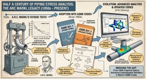
過去逾半個世紀以來,工業界廣泛應用的 ASME B31.1(動力管線)與 ASME B31.3(製程管線)規範,在計算應力增強係數(Stress Intensification Factor, SIF)與柔性係數(Flexibility Factor, k -factor)時,均高度仰賴 1950 年代由 A.R.C. Markl 針對 4 吋標準壁厚無縫管件所進行的疲勞測試數據,並將這些基於特定幾何參數外推的經驗公式編列於 Appendix D 之中。然而,隨著現代管線工程的管徑不斷增大、厚徑比(D/t)趨於極端化,以及高階耐熱合金材料強度的顯著提升,Appendix D 內過於簡化的單一純量公式,已無法精確反映複雜交會管件在三維空間中的受力特徵與局部變形。為此,最新發布的 ASME B31.3(2020/2022 年版)與 ASME B31.1(2024/2026 年版)已正式廢除長期使用的 Appendix D,並強制導入基於現代高精度有限元素分析(FEA)與海量實體驗證數據建構的 ASME B31J 規範。 For over half a century, the widely applied ASME B31.1 (Power Piping) and ASME B31.3 (Process Piping) codes relied heavily on fatigue test data conducted by A.R.C. Markl in the 1950s on 4-inch standard wall seamless pipe components when calculating the Stress Intensification Factor (SIF) and Flexibility Factor (k-factor), compiling these empirical formulas based on specific geometric parameter extrapolations into Appendix D. However, with the continuous increase in pipe diameters, extreme diameter-to-thickness (D/t) ratios in modern piping engineering, and the significant improvement in the strength of advanced heat-resistant alloys, the overly simplified single-scalar formulas in Appendix D can no longer accurately reflect the stress characteristics and local deformations of complex intersecting components in three-dimensional space. To this end, the newly released ASME B31.3 (2020/2022 Editions) and ASME B31.1 (2024/2026 Editions) have officially abolished the long-used Appendix D and mandated the implementation of the ASME B31J code, which is built upon modern high-precision Finite Element Analysis (FEA) and massive empirical validation data.
ASME B31J 的強制導入在工程界引發了深遠的「應力分析衝擊(Stress Analysis Shock)」。其嶄新的數值矩陣與解耦演算法揭示了許多依據舊有規範設計的既有管線,在持續負載與熱位移下,實際上存在著嚴重的隱藏應力超標熱點。本研究旨在深入剖析 B31J 導入後,B31.1 與 B31.3 在持續應力檢核與疲勞壽命評估上的底層物理與數學差異。同時,針對高階潛變增強型鐵素體鋼(如 P91、P92 鋼材)在冷作加工中所面臨的冶金瓶頸,系統性解析 ASME 規範對應變率(5%~20%)放寬的力學基礎,以及其對感應加熱彎管後熱處理(IH-PBHT)適用性的決定性影響。 The mandatory implementation of ASME B31J has triggered a profound “Stress Analysis Shock” in the engineering industry. Its novel numerical matrices and decoupling algorithms reveal that many existing pipelines designed under the old codes actually possess severe hidden stress-exceeding hotspots under sustained loads and thermal displacements. This study aims to deeply analyze the underlying physical and mathematical differences between B31.1 and B31.3 in sustained stress evaluation and fatigue life assessment after the introduction of B31J. Simultaneously, addressing the metallurgical bottlenecks faced during the cold working of advanced creep-strength-enhanced ferritic steels (such as P91 and P92 steels), this study systematically parses the mechanical basis for the ASME code’s relaxation of the strain rate limit (5%~20%) and its decisive impact on the applicability of Induction Heating Post-Bend Heat Treatment (IH-PBHT).
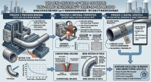
為突破傳統管線設計中常規支架最佳化方案的物理與空間侷限,本研究將重點導入並探討潁璋工程(Ying-Zhang Engineering)所研發之「三合一工法」——即 3D/5D CNC 大半徑冷作彎管、IH-PBHT 單管感應亞臨界彎後熱處理與 QR Code 數位履歷之整合應用。藉由「能彎不銲(Bend-instead-of-weld)」的核心力學理念,論證如何將易受流體沖刷與 Type IV 潛變破壞的傳統電銲接頭,轉化為應力平滑過渡的母材彎曲段,從而全面符合最新 ASME B31.1 與 B31J 對現代高能管線生命週期管理的嚴格要求。 To break through the physical and spatial limitations of conventional support optimization strategies in traditional piping design, this study will focus on introducing and exploring the “Three-in-One Method” developed by Ying-Zhang Engineering—namely, the integrated application of 3D/5D CNC large-radius cold bending, IH-PBHT single-pipe induction subcritical post-bend heat treatment, and QR Code digital traceability. Through the core mechanical concept of “Bend-instead-of-weld,” this study demonstrates how to transform traditional welded joints, which are susceptible to fluid erosion and Type IV creep damage, into stress-smooth transitioned base metal bends, thereby fully complying with the stringent life-cycle management requirements for modern high-energy piping under the latest ASME B31.1 and B31J codes.
二、 方法與規範解析 / II. Methodology and Code Analysis
2.1 規範管轄邊界與基礎強度設計原則之分歧 / 2.1 Divergence in Jurisdictional Boundaries and Fundamental Strength Design Principles
在進行深入的應力解耦分析前,確立 ASME 管線規範的管轄邊界與設計哲學是首要之務。ASME B31.1 的管轄範圍嚴格聚焦於發電站、工業動力廠與區域供熱系統中的管線;特別是直接連接至動力鍋爐、直到第一道隔離閥之間的「鍋爐外部管線(Boiler External Piping, BEP)」。此高壓蒸汽區段同時受到 ASME 鍋爐與壓力容器規範(BPVC Section I)的強制管轄,並要求取得嚴格的 ASME 鋼印認證。相對地,ASME B31.3 則具備最廣泛的工業涵蓋面,統轄煉油廠、化學合成廠、製藥廠以及 LNG 接收站內的所有製程管線(Process Piping);即便在石化工廠內部,輔助蒸汽鍋爐系統在跨越主隔離閥的管轄分界點後,亦將自動由 B31.1 轉換為 B31.3 進行管轄。 Before conducting an in-depth stress decoupling analysis, establishing the jurisdictional boundaries and design philosophies of the ASME piping codes is a top priority. The jurisdiction of ASME B31.1 strictly focuses on piping in power stations, industrial power plants, and district heating systems; particularly the “Boiler External Piping (BEP)” connecting directly from the power boiler up to the first isolation valve. This high-pressure steam section is simultaneously under the mandatory jurisdiction of the ASME Boiler and Pressure Vessel Code (BPVC Section I) and requires strict ASME stamping certification. In contrast, ASME B31.3 possesses the broadest industrial coverage, governing all Process Piping within oil refineries, chemical synthesis plants, pharmaceutical plants, and LNG receiving terminals; even within a petrochemical plant, the auxiliary steam boiler system will automatically transition from B31.1 to B31.3 jurisdiction after crossing the jurisdictional boundary point of the main isolation valve.
在基礎設計強度與安全裕度(Safety Margin)的設定上,兩者存在根本性的數學分歧。ASME B31.1 著眼於發電廠長達 40 年的工廠生命週期,以及發生事故時對公眾與工廠安全的毀滅性影響,因此採用極度保守的設計裕度。歷史上,B31.1 的基本容許應力(S)取自材料在設計溫度下最小抗拉強度(ST)的 1/4,後續為與 ASME Section II Part D Table 1A 保持一致,微調為 1/3.5。反觀 ASME B31.3,其設計理念在於賦予工程師更大的靈活性以追求製程經濟效益,容許較短的 20 至 30 年設計壽命;其容許應力基準取抗拉強度的 1/3 與降伏強度的 2/3 之較低值,基本安全係數約落在 3.0。 Regarding the setting of fundamental design strength and safety margins, a fundamental mathematical divergence exists between the two. ASME B31.1 focuses on the 40-year plant life cycle of power plants and the devastating impact on public and plant safety in the event of an accident, thus adopting extremely conservative design margins. Historically, the basic allowable stress (S) of B31.1 was taken as 1/4 of the specified minimum tensile strength (ST) at the design temperature, which was later fine-tuned to 1/3.5 to align with ASME Section II Part D Table 1A. Conversely, the design philosophy of ASME B31.3 aims to grant engineers greater flexibility to pursue process economic efficiency, allowing a shorter design life of 20 to 30 years; its allowable stress basis takes the lower of 1/3 of the tensile strength or 2/3 of the yield strength, with a basic safety factor of approximately 3.0.
| 比較參數與力學指標 / Comparison Parameters & Mechanical Indicators | ASME B31.1 (動力管線規範 / Power Piping Code) | ASME B31.3 (製程管線規範 / Process Piping Code) |
| 主要管轄場域與系統 / Main Jurisdictional Fields & Systems | 發電廠、鍋爐外部管線 (BEP)、區域供熱 / Power plants, Boiler External Piping (BEP), district heating | 石化煉油、化學合成、製藥與 LNG 終端設施 / Petrochemical refining, chemical synthesis, pharmaceuticals, and LNG terminals |
| 基本安全係數 / Basic Safety Factor | 約 4.0 演進至 3.5 (強調極致可靠性與機械完整性) / ~4.0 evolved to 3.5 (Emphasizes extreme reliability & mechanical integrity) | 約 3.0 (強調工程靈活性與全生命週期經濟性) / ~3.0 (Emphasizes engineering flexibility & lifecycle economics) |
| 典型設計生命週期 / Typical Design Life Cycle | 40 年 / 40 years | 20 – 30 年 / 20 – 30 years |
| 對接銲縫強度折減 (W 因子) / Butt Weld Strength Reduction (W Factor) | 不適用 (仰賴極度嚴苛之 NDE 檢驗預防) / N/A (Relies on extremely strict NDE to prevent) | 強制適用於高溫潛變區間 / Mandatory in the high-temperature creep regime |
2.2 縱向壓力與持續應力檢核之 2024 年版重大變革 / 2.2 2024 Edition Major Revisions on Longitudinal Pressure and Sustained Stress Evaluation
在針對管線系統承受恆定重力與內部壓力所產生的持續應力(Sustained Stress),以及熱位移產生的熱膨脹應力(Expansion Stress)進行評估時,B31.1 與 B31.3 的數學模型展現出截然不同的邏輯。B31.3 在熱膨脹容許應力範圍(SA)的計算中,直接採用將縱向應力整合的公式SA=f⋅[1.25(Sc+Sh )-SL ] 。公式中的 SL代表由壓力與重力等持續負載引起的縱向應力,它會直接消耗並折減可用的熱膨脹應力預算;若持續負載維持在較低水平,剩餘的應力裕度即可轉移給熱膨脹使用,體現了所謂「Liberal Allowable」的彈性設計概念。同時,面對頻繁啟停的高頻循環服役環境,B31.3 大幅陡峭化了疲勞應力範圍折減因子(f)的衰減曲線,顯著收緊了高頻服役下的應力預算。 When evaluating the Sustained Stress caused by constant gravity and internal pressure on the piping system, as well as the Expansion Stress caused by thermal displacement, the mathematical models of B31.1 and B31.3 exhibit distinctly different logics. In calculating the thermal expansion allowable stress range (SA), B31.3 directly adopts a formula that integrates longitudinal stress: SA=f⋅[1.25(Sc+Sh )-SL ]. The SL in this formula represents the longitudinal stress caused by sustained loads such as pressure and gravity, which directly consumes and reduces the available thermal expansion stress budget; if sustained loads are kept at a low level, the remaining stress margin can be transferred for thermal expansion use, embodying the elastic design concept known as “Liberal Allowable.” Meanwhile, facing the high-frequency cyclic service environment of frequent startups and shutdowns, B31.3 significantly steepens the decay curve of the fatigue stress range reduction factor (f), substantially tightening the stress budget under high-frequency service.
另一方面,2024 年版的 ASME B31.1 針對持續應力檢核做出了極其嚴苛的修訂。針對管內壓力產生的縱向壓力(Slp),B31.1 廢除了過去廣泛適用於薄壁管件的近似公式(如PD/4t),因這類公式在面對超超臨界(USC)電廠極端厚徑比的高溫厚壁管線時,會產生嚴重的非保守誤差。新規範明文要求,必須回歸基於厚壁圓筒理論的 Lamé 方程式來進行精確計算:On the other hand, the 2024 edition of ASME B31.1 made extremely stringent revisions to sustained stress evaluation. Regarding the longitudinal pressure stress (Slp) generated by internal pipe pressure, B31.1 abolished the approximation formulas (such as PD/4t) previously widely applied to thin-walled components, because such formulas produce severe non-conservative errors when dealing with high-temperature thick-walled piping with extreme diameter-to-thickness ratios in Ultra-Supercritical (USC) power plants. The new code explicitly requires a return to the Lamé equation based on thick-walled cylinder theory for precise calculation:
Slp=(P⋅d2)/(D2-d2 )
在此公式中,P 為內部設計壓力,D 為名目外徑,而 d 為管線的有效內徑。規範特別強調,在計算有效內徑 d 時,必須嚴格扣除所有的腐蝕裕度(Corrosion Allowance)、沖蝕裕度(Erosion Allowance)以及機械加工裕度(如車牙深度)後,取最惡劣情況下的淨內徑代入運算。此外,B31.1 2024 年版同步刪除了偶發負載評估中對於重合壓力(Coincident Pressure)的舊有定義,統一且簡化了壓力與動態地震或風壓負載的疊加計算邏輯。 In this formula, P is the internal design pressure, D is the nominal outside diameter, and d is the effective inside diameter of the pipe. The code particularly emphasizes that when calculating the effective inside diameter d, all corrosion allowances, erosion allowances, and mechanical machining allowances (such as threading depth) must be strictly deducted, taking the net inside diameter under the worst-case scenario for the calculation. Furthermore, the 2024 edition of B31.1 simultaneously deleted the old definition of Coincident Pressure in occasional load evaluation, unifying and simplifying the superposition calculation logic for pressure and dynamic seismic or wind loads.
2.3 ASME B31J 的力學機制解耦與 SSI 導入 / 2.3 Mechanical Mechanism Decoupling and SSI Introduction in ASME B31J
在過去 B31.3 Appendix D 的計算邏輯中,管件的應力增強係數被簡化為單一純量(i),其數值完全由簡化後的柔性特徵值(Flexibility Characteristic)決定。這種源自 1950 年代的經驗公式存在多重物理盲點:它未考量分支管的外徑與壁厚比例對主運行管(Run pipe)結構剛性的實質影響;更為致命的是,舊規範將管件承受平面內(In-Plane)與平面外(Out-of-Plane)彎矩的影響強行混合,統一取兩者中的最大 SIF 值套用於整個幾何節點,並且草率地將扭轉應力增強係數預設為剛體(即 1.0)。 In the past calculation logic of B31.3 Appendix D, the stress intensification factor of a component was simplified into a single scalar (i), the value of which was completely determined by the simplified Flexibility Characteristic. This empirical formula originating from the 1950s had multiple physical blind spots: it failed to consider the substantive impact of the branch pipe’s outer diameter to wall thickness ratio on the structural rigidity of the run pipe; more fatally, the old code forcibly mixed the effects of In-Plane and Out-of-Plane bending moments borne by the component, uniformly applying the maximum SIF value of the two to the entire geometric node, and hastily defaulting the torsional stress intensification factor to a rigid body (i.e., 1.0).
ASME B31J 的強制導入,為管線應力分析帶來了建立在現代有限元素分析(FEA)與實體疲勞測試基礎上的高精度解耦框架:The mandatory introduction of ASME B31J brings a high-precision decoupling framework for piping stress analysis based on modern Finite Element Analysis (FEA) and physical fatigue testing:
- 自由度維度解耦:B31J 不再使用單一 SIF,而是針對每個複雜管件(如三通、漸縮管、彎頭)提供三組獨立的 SIF 方程式,精確定義了平面內(ii)、平面外(io)以及扭轉(it)三個向量方向的應力放大倍率。這徹底消除了過去將管件彎曲變形與剪切扭轉混為一談的過度保守設計。Degree of Freedom Dimensional Decoupling: B31J no longer uses a single SIF; instead, it provides three independent SIF equations for each complex component (e.g., tees, reducers, elbows), precisely defining the stress amplification multipliers in three vector directions: In-Plane (ii), Out-of-Plane (io), and Torsional (it). This completely eliminates the overly conservative design of the past that conflated component bending deformation with shear torsion.
- 物理破壞機制解耦(SIF vs. SSI):這項變革對應力評估產生了最深遠的影響。B31J 強制將主導「動態局部疲勞破壞」的應力增強係數(SIF)與主導「靜態全截面塑性崩塌」的持續應力指數(Sustained Stress Index, SSI)在物理機制上進行徹底脫鉤。在舊版 Appendix D 的粗略框架下,SSI 往往被簡單定義為 75i,導致工程師在評估恆定重力與壓力造成的靜態崩塌風險時,錯誤地套用了局部高頻疲勞的幾何放大因子。B31J 明文確立了獨立的 SSI 計算邏輯與下限防線(SSI 絕對不得小於 1.0),並要求回歸使用匹配直管的標準截面模數 Z 來執行持續應力的檢核。此舉使厚壁管線能更科學地釋放空間設計潛力,同時防堵薄壁管在靜態負載下的結構盲區。Physical Failure Mechanism Decoupling (SIF vs. SSI): This revision has the most profound impact on stress evaluation. B31J mandates the complete decoupling of the Stress Intensification Factor (SIF), which dominates “dynamic local fatigue failure,” from the Sustained Stress Index (SSI), which dominates “static full cross-section plastic collapse,” in their physical mechanisms. Under the rough framework of the old Appendix D, SSI was often simply defined as 0.75i, causing engineers to mistakenly apply the geometric amplification factor for local high-frequency fatigue when evaluating the static collapse risk caused by constant gravity and pressure. B31J explicitly establishes an independent SSI calculation logic and a lower limit defense line (SSI must absolutely not be less than 1.0), and requires a return to using the standard section modulus Z matching a straight pipe to perform sustained stress evaluation. This move allows thick-walled piping to scientifically release spatial design potential while plugging the structural blind spots of thin-walled pipes under static loads.
目前,工業界廣泛使用的管線應力分析軟體(如 CAESAR II)已透過整合 FEATools 模組,全面支援 B31J 的龐大矩陣運算。當工程師在軟體介面中啟用 B31J 後,系統會自動在背景利用高階曲面有限元素演算法,即時推導出符合該特定幾何形狀的 i-factors、k-factors 與 SSI,並將其直接反饋至線性或非線性的靜動態載荷運算核心中。 Currently, widely used piping stress analysis software in the industry (such as CAESAR II) fully supports the massive matrix calculations of B31J by integrating the FEATools module. When an engineer enables B31J in the software interface, the system will automatically utilize high-order surface finite element algorithms in the background to deduce in real-time the i-factors, k-factors, and SSI conforming to that specific geometry, feeding them directly into the linear or non-linear static and dynamic load calculation cores.
三、 結果:應力重新分布與傳統組件的物理極限 / III. Results: Stress Redistribution and Physical Limits of Traditional Components
3.1 B31J 導入後的隱藏熱點浮現 / 3.1 Emergence of Hidden Hotspots after B31J Implementation
當工程師在 CAESAR II 軟體中,將既有大型高能管線(如 CCPP 的主蒸汽管、熱段再熱管或石化工廠的高壓合成氣管線)的數位模型,由舊版規範切換至強制性的 B31J 模組後,應力分佈結果往往呈現出極端的分化現象,徹底顛覆了原有的設計認知。 When engineers switch the digital models of existing large high-energy pipelines (such as CCPP main steam lines, hot reheat lines, or petrochemical high-pressure syngas lines) from the old code to the mandatory B31J module in CAESAR II software, the stress distribution results often exhibit extreme polarization, completely overturning original design perceptions.
根據 B31J 透過 FEA 反饋的精確數據,對於厚度變化懸殊或分支直徑比(d/D)較小的分支連接件(如 Weldolets)、漸縮管或補強三通,其真實的應力集中效應遠高於 Appendix D 時代的低估值。薄壁母管在承受厚壁支管傳遞的巨大集中彎矩時,極易在管壁交界處產生嚴重的局部降伏。反之,對於傳統的短半徑彎頭(Short Radius Elbows)或是斜接彎管(Mitre Bends),其平面內與平面外的 SIF 預測值則獲得了大幅下修,使得這類管件在熱膨脹迴圈中的保守度減少了約 20% 至 45%。 According to the precise data fed back by B31J via FEA, for branch connections with drastic thickness variations or small branch diameter ratios (d/D) (like Weldolets), reducers, or reinforced tees, their true stress concentration effects are far higher than the underestimated values of the Appendix D era. When a thin-walled run pipe bears the immense concentrated bending moment transmitted by a thick-walled branch pipe, it is highly prone to severe local yielding at the pipe wall junction. Conversely, for traditional Short Radius Elbows or Mitre Bends, their in-plane and out-of-plane SIF predicted values receive substantial downward revisions, reducing the conservatism of these components in thermal expansion loops by about 20% to 45%.
這種力學參數的重新洗牌,加上 2024 年版 B31.1 對縱向壓力應力採用淨內徑與厚壁 Lamé 方程式的嚴格要求,導致許多在舊規範下剛好及格(應力比落在 90%~95% 邊緣)的管線系統,在切換至 B31J 後,於支管交會處(Branch Connections)與高載荷設備端點(Equipment Nozzles)大量浮現應力比超過 100% 容許極限的危險熱點。 This reshuffling of mechanical parameters, combined with the strict requirement of the 2024 edition of B31.1 to use the net internal diameter and thick-walled Lamé equation for longitudinal pressure stress, leads to a situation where many piping systems that barely passed under the old code (with stress ratios on the 90%~95% borderline) exhibit a massive emergence of dangerous hotspots exceeding the 100% allowable limit at Branch Connections and Equipment Nozzles after switching to B31J.
3.2 傳統 1.5D 電銲彎頭的系統性致命缺陷 / 3.2 Systemic Fatal Flaws of Traditional 1.5D Welded Elbows
在空間受限與 B31J 嚴格應力檢核的雙重夾擊下,傳統工程中被廣泛作為轉向樞紐的 1.5D 短半徑電銲彎頭(1.5D Welded Elbows),逐漸暴露出其在系統生命週期中最致命的結構與冶金缺陷:Under the dual squeeze of spatial constraints and strict B31J stress evaluations, the 1.5D Short Radius Welded Elbows traditionally widely used as directional pivots in engineering are gradually exposing their most fatal structural and metallurgical flaws in the system life cycle:
- 冶金衰退與第四型潛變破裂 (Type IV Creep Cracking):傳統1.5D 彎頭無可避免地帶有環向對接銲縫。在 ASME B31.1 的設定中,為反映發電系統對高可靠性的要求,對接銲接接頭的 SIF 最高可被放大至 1.9;而 B31.3 在高溫潛變區間內,更強制要求計算銲縫強度折減因子(W 因子)。對於現代超超臨界機組與 CCPP 中廣泛採用的高階潛變強度增強型鐵素體鋼(CSEF,如 P91、P92 鋼材),其銲接熱影響區(HAZ),特別是處於臨界溫度的細晶區(FGHAZ),在高溫高壓與頻繁啟停熱循環交互作用下,極易發生冶金組織劣化與微洞穴(Cavities)成核,最終導致無預警且毀滅性的第四型潛變破裂。Metallurgical Degradation and Type IV Creep Cracking: Traditional 1.5D elbows inevitably carry circumferential butt welds. In the settings of ASME B31.1, reflecting the high reliability requirements for power generation systems, the SIF of butt welded joints can be amplified up to 1.9; whereas B31.3 mandates the calculation of a weld joint strength reduction factor (W Factor) in the high-temperature creep regime. For advanced Creep-Strength-Enhanced Ferritic steels (CSEF, such as P91, P92 steels) widely adopted in modern ultra-supercritical units and CCPP, their weld Heat-Affected Zones (HAZ), especially the Fine-Grained HAZ (FGHAZ) located at critical temperatures, are highly susceptible to metallurgical structural degradation and micro-cavity nucleation under the interactive effects of high temperature, high pressure, and frequent startup-shutdown thermal cycling, ultimately leading to unpredictable and devastating Type IV creep cracking.
- 流體力學損害與熱衝擊 (FAC & Thermal Shock):1.5D 彎頭的幾何曲率半徑極小,當高溫高壓的主蒸汽或帶有液滴的兩相流高速通過轉向區時,極度不平滑的流道會引發劇烈的內部紊流、邊界層剝離(Boundary Layer Separation)與強烈的二次流現象。這些流體力學異常不僅會造成嚴重的流體加速腐蝕(Flow-Accelerated Corrosion, FAC)不斷削薄管壁,當機組冷態啟動或熱負載劇變時,紊流更會加劇管壁局部的淬火效應(Quenching Effect)與熱衝擊。流固耦合效應若與 B31J 演算法下放大的局部疲勞應力疊加,將使 1.5D 電銲彎頭成為整套高能管線中最易發生早期破裂的定時炸彈。Fluid Mechanical Damage and Thermal Shock: The geometric radius of curvature of 1.5D elbows is extremely small. When high-temperature, high-pressure main steam or two-phase flow with droplets passes through the turning area at high speeds, the extremely unsmooth flow channel triggers severe internal turbulence, Boundary Layer Separation, and strong secondary flow phenomena. These fluid mechanical anomalies not only cause severe Flow-Accelerated Corrosion (FAC) that continuously thins the pipe wall, but when the unit starts up from a cold state or experiences drastic thermal load changes, the turbulence further exacerbates localized Quenching Effects and thermal shocks on the pipe wall. If fluid-solid coupling effects are superimposed with the amplified local fatigue stress under the B31J algorithm, 1.5D welded elbows become ticking time bombs most prone to early rupture in the entire high-energy piping system.
四、 討論:物理成型與熱處理的跨領域技術交匯 / IV. Discussion: Cross-Disciplinary Intersection of Physical Forming and Heat Treatment
為徹底拔除由銲縫與急彎所引發的系統性結構缺陷,將管線設計思維從「傳統銲接彎頭」轉向「一體成型的大半徑冷作無縫彎管」已成為高能管線工程的必然演進趨勢。然而,金屬管材在室溫下的冷作彎曲加工,無可避免地會在其晶格內部引入塑性變形與加工硬化(Strain Hardening)。To thoroughly eradicate the systemic structural defects triggered by welds and sharp bends, shifting the piping design mindset from “traditional welded elbows” to “integrally formed large-radius cold seamless bends” has become the inevitable evolutionary trend in high-energy piping engineering. However, the cold bending processing of metal pipes at room temperature inevitably introduces plastic deformation and Strain Hardening into their crystal lattices.
4.1 應變率控制與極限纖維伸長率(EFE)的物理意涵 / 4.1 Physical Implications of Strain Rate Control and Extreme Fiber Elongation (EFE)
冷作彎管的工程品質防線,首先建立在對「極限纖維伸長率」(Extreme Fiber Elongation, EFE)的精確計算與控制上。在金屬管彎曲的物理過程中,位於彎管外緣(Extrados)的纖維受到極大的拉伸應變,而內緣(Intrados)則承受壓縮應變。根據 ASME BPVC Section VIII UCS-79 或相應的 B31 規定,圓管成型應變率的計算公式大抵遵循以下物理幾何邏輯:The engineering quality defense line of cold-bent pipes is first established on the precise calculation and control of Extreme Fiber Elongation (EFE). During the physical process of metal pipe bending, the fibers located at the Extrados of the bend are subjected to extreme tensile strain, while the Intrados bears compressive strain. According to ASME BPVC Section VIII UCS-79 or corresponding B31 regulations, the calculation formula for the forming strain rate of round pipes generally follows this physical geometric logic:
EFE(%)=ro/R×100≈50t/R
(公式中 ro 代表管材名目外半徑,t 為名目壁厚,而 R 為彎曲中心半徑)。(In the formula, ro represents the nominal outside radius of the pipe, t is the nominal wall thickness, and R is the bend centerline radius).
由公式可知,冷作應變率與彎曲半徑成反比。大量的實體量測與數值分析證實,若採用 5D 彎管,其冷作應變率可普遍控制在 10.0% 左右甚至更低的安全區間,從而大幅減輕了材料內部的晶格扭曲程度。 From the formula, it is known that the cold work strain rate is inversely proportional to the bending radius. A massive amount of physical measurements and numerical analyses confirm that if 5D bends are used, their cold work strain rate can generally be controlled within a safe range of about 10.0% or even lower, thereby significantly mitigating the degree of lattice distortion inside the material.
五、 實務應用與多維度視角剖析:三合一工法之深度實踐 / V. Practical Application and Multi-Dimensional Perspective Analysis: Deep Practice of the Three-in-One Method
面對上述極端服役條件與新規範(B31J、B31.1 2024/2026年版)的雙重挑戰,實務工程界必須提出系統性的解決方案。本章將極度深入地剖析「業主、EPC 承包商、廠務、協力廠商」在管線營運、設計與施作上的痛點,並論證潁璋工程(Ying-Zhang Engineering)「能彎不銲」三合一工法的核心價值與合規性落實。Facing the dual challenges of the aforementioned extreme service conditions and new codes (B31J, B31.1 2024/2026 Editions), the practical engineering sector must propose systematic solutions. This chapter will deeply analyze the pain points in pipeline operation, design, and construction from the perspectives of “Owners, EPC Contractors, Plant Managers, and Subcontractors,” and demonstrate the core value and compliance implementation of the “Three-in-One Method” (“Bend-instead-of-weld”) by Ying-Zhang Engineering.
5.1 業主視角:管線銲道維護管理與全生命週期營運決策 / 5.1 Owner’s Perspective: Piping Weld Maintenance Management and Life-Cycle Operational Decision-Making
對於發電廠或石化工廠業主而言,高能管線的「全生命週期維護成本(OPEX)」與「非計畫性停機風險」是營運決策的重中之重。在傳統 1.5D 銲接彎頭系統中,銲縫不可避免地成為應力集中與潛變劣化(如 Type IV 破裂)的熱點。這迫使業主在每次歲修時必須投入龐大預算進行非破壞性檢驗(NDT,如超音波、射線攝影),甚至需頻繁更換管件。 For power plant or petrochemical plant owners, the “Operational Expenditure (OPEX) over the entire life cycle” and “unplanned outage risks” of high-energy piping are the top priorities in operational decision-making. In traditional 1.5D welded elbow systems, welds inevitably become hotspots for stress concentration and creep degradation (such as Type IV cracking). This forces owners to invest massive budgets in Non-Destructive Testing (NDT, such as ultrasound or radiography) during each turnaround, or even frequently replace pipe components.
透過導入無縫冷作彎管,從源頭物理性地消除最脆弱的轉向區環向對接銲縫,業主能顯著降低生命週期中的 NDT 檢驗成本,並免除因銲道洩漏引發的工安風險。這種基於「避免損壞機制」的營運決策,極大化了廠房機組在頻繁啟停深調峰模式下的資產可靠度。 By introducing seamless cold bends, which physically eliminate the most vulnerable circumferential butt welds in the turning zones from the source, owners can significantly reduce NDT inspection costs during the life cycle and eliminate industrial safety risks triggered by weld leaks. This operational decision based on the “damage avoidance mechanism” maximizes the asset reliability of plant units under the frequent cycling and deep load-following modes.
5.2 EPC 承包商與設計單位視角:空間佈置優化與實務考量 / 5.2 EPC Contractor and Design Unit’s Perspective: Spatial Layout Optimization and Practical Considerations
現代化的 CCPP 廠區往往面臨極度嚴苛的空間受限(Space-constrained)問題。若採用傳統方式擴大熱膨脹環,不僅會佔用龐大的空間足跡(Footprint),更會增加材料成本與系統壓降。 Modernized CCPP plant areas often face extremely stringent Space-constrained issues. If traditional methods are used to expand thermal expansion loops, it will not only occupy a massive Footprint but also increase material costs and system pressure drops.
EPC 廠的管線應力工程師在面對 B31J 嚴格的應力檢核時,若繼續沿用 1.5D 電銲彎頭,經常會遇到設備管嘴載荷(Nozzle Loads)超標的問題,導致難以與旋轉設備(如汽輪機)安全對接。此時,5D 大半徑冷作彎管的導入便成為破局關鍵:其本質上具備優異的自然柔性(Flexibility),且在 B31J 運算下,其 SIF 指數呈現指數級衰減,幾乎逼近於 1.0。這讓 EPC 設計單位能大幅減少對剛性支撐架(Rigid Hangers)的依賴,完美解決跨領域空間干涉(Clash)的實務難題,並將極度敏感的旋轉設備管嘴應力降至最低。 When facing the strict stress evaluation of B31J, if piping stress engineers at EPC firms continue to use 1.5D welded elbows, they frequently encounter issues with Equipment Nozzle Loads exceeding limits, making it difficult to safely connect with rotating equipment (such as steam turbines). At this point, the introduction of 5D large-radius cold bends becomes the key to breaking the deadlock: it inherently possesses excellent natural Flexibility, and under B31J calculations, its SIF index exhibits exponential decay, approaching 1.0. This allows EPC design units to significantly reduce reliance on Rigid Hangers, perfectly solving the practical challenge of cross-disciplinary spatial Clash, and minimizing the nozzle stresses of highly sensitive rotating equipment.
5.3 廠務管理者視角:防範流體力學損害與確保運轉安全 / 5.3 Plant Manager’s Perspective: Preventing Fluid Mechanical Damage and Ensuring Operational Safety
從廠務管理者(Plant Manager)的第一線運轉視角來看,高壓蒸汽管線或兩相流系統的「流體加速腐蝕(FAC)」與「熱衝擊(Thermal Shock)」是威脅廠房安全的兩大隱形殺手。From the frontline operational perspective of a Plant Manager, “Flow-Accelerated Corrosion (FAC)” and “Thermal Shock” in high-pressure steam pipelines or two-phase flow systems are two major invisible killers threatening plant safety.
1.5D 短半徑彎頭因急彎導致嚴重的邊界層剝離與二次流紊流,極易造成局部管壁薄化或啟動時的淬火效應。冷作彎管藉由巨大且平滑的曲率半徑,從流體力學的物理本質上消除了這些劇烈的內部紊流,提供平順的流道。廠務端要求採用冷作彎管,正是為了拔除這種流固耦合(FSI)下引發的早期破裂定時炸彈,確保前線人員安全並維持穩定的製程產能。 1.5D short-radius elbows, due to their sharp bends, lead to severe boundary layer separation and secondary flow turbulence, which easily causes localized pipe wall thinning or quenching effects during startup. Cold bends, with their massive and smooth radii of curvature, eliminate these violent internal turbulences from the physical essence of fluid mechanics, providing a smooth flow channel. The plant management’s requirement to adopt cold bends is precisely to remove this early rupture time bomb triggered under Fluid-Solid Interaction (FSI), ensuring the safety of frontline personnel and maintaining stable process throughput.
5.4 協力廠商視角:高階管線要求與專業因應策略 / 5.4 Subcontractor’s Perspective: High-End Piping Requirements and Professional Response Strategies
從冷作彎管施作協力廠商(如潁璋工程)的角度來看,面對 P91 等對應變與溫度極度敏感的高階耐熱合金,僅符合行業基本規範已遠遠不足以保證最終品質。 From the perspective of cold bending subcontractors (such as Ying-Zhang Engineering), facing high-end heat-resistant alloys like P91 that are extremely sensitive to strain and temperature, merely meeting basic industry standards is far from enough to guarantee final quality.
協力廠商必須具備超越標準的專業能力,制定嚴謹的因應策略。首先,必須全面導入高精度 CNC 電腦數值控制,動態監控並精準計算管材彎曲當下的「極限纖維伸長率(EFE)」。其次,協力廠商應將自身定位為 EPC 與業主的「長期策略夥伴」,從前期的彎管技術諮詢、3D/5D 試彎曲檢驗,到後續的彎後熱處理與無損檢測,提供風險控管的全方位協作服務,以確保出廠管件的機械性能與設計預期百分之百吻合。 Subcontractors must possess professional capabilities that exceed standards and formulate rigorous response strategies. First, high-precision CNC (Computer Numerical Control) must be fully introduced to dynamically monitor and precisely calculate the Extreme Fiber Elongation (EFE) at the moment of pipe bending. Second, subcontractors should position themselves as “long-term strategic partners” to EPCs and owners, providing all-around collaborative services for risk control—from preliminary pipe bending technical consultation and 3D/5D trial bending inspection, to subsequent post-bend heat treatment and non-destructive testing—to ensure that the mechanical properties of the factory-delivered components match design expectations 100%.
5.5 導入潁璋工程「三合一工法」之管理核心價值優化 / 5.5 Management Core Value Optimization of Introducing Ying-Zhang Engineering’s “Three-in-One Method”
為完美整合上述多維度的需求,潁璋工程提倡並徹底落實了「三合一工法」——即深度整合「3D/5D CNC 大半徑冷作彎管」、「IH-PBHT 單管感應亞臨界彎後熱處理」以及「QR Code 雲端數位履歷」。To perfectly integrate the aforementioned multi-dimensional needs, Ying-Zhang Engineering advocated and thoroughly implemented the “Three-in-One Method”—namely, deeply integrating “3D/5D CNC large-radius cold bending,” “IH-PBHT single-pipe induction subcritical post-bend heat treatment,” and “QR Code cloud digital traceability.”
此工法管理的核心價值,在於將傳統工程中各自獨立的製造、冶金與品管孤島予以打通。透過數位履歷系統,每一組出廠的 5D 冷彎管件皆綁定專屬的 QR Code,工程師掃描後即可連入雲端讀取初始材料爐號、CNC 成型當下的 EFE 數值以及 IH-PBHT 時溫曲線。這不僅優化了生產流程的可追溯性,更為未來結合 IoT 感測數據、構建數位孿生(Digital Twin)與動態更新 B31J 疲勞壽命預測,奠定了無可取代的數據基盤。 The core value of this method’s management lies in breaking down the isolated silos of manufacturing, metallurgy, and quality control in traditional engineering. Through the digital traceability system, each factory-delivered 5D cold-bent component is bound with an exclusive QR Code. After scanning, engineers can access the cloud to read the initial material Heat Number, the EFE value at the moment of CNC forming, and the IH-PBHT time-temperature curve. This not only optimizes the traceability of the production process but also establishes an irreplaceable data foundation for integrating IoT sensor data, building a Digital Twin, and dynamically updating B31J fatigue life predictions in the future.
5.6 落實「能彎不銲」設計理念與三合一工法之合規執行 / 5.6 Implementing the “Bend-instead-of-weld” Design Philosophy and Compliance Execution of the Three-in-One Method
「能彎不銲(Bend-instead-of-weld)」絕不僅是一句口號,而是嚴格對接最新 ASME B31.1 與 B31J 規範的合規性展現。 “Bend-instead-of-weld” is by no means just a slogan; it is a manifestation of strict compliance interfacing with the latest ASME B31.1 and B31J codes.
在設計階段,應力工程師藉由導入 B31J 的數值分析框架,確認 5D 彎管的 SIF 近乎 1.0 的力學優勢,並將其回饋至 CAESAR II 軟體中,以符合 B31.1 2024/2026 對厚壁管與持續應力(SSI)的嚴苛解耦要求。在製造階段,三合一工法的實踐確保了管材從室溫下的 CNC 精密冷彎到後續的微觀組織回復,全程置於嚴密的參數監控之下。這種將容易產生應力集中與 Type IV 破裂的環向對接銲縫,徹底轉化為連續平滑母材彎曲段的執行理念,正是現代高能管線突破傳統疲勞瓶頸的唯一解方。 In the design phase, stress engineers use the numerical analysis framework of B31J to confirm the mechanical advantage of 5D bends (SIF approaching 1.0) and feed it back into CAESAR II software to meet the stringent decoupling requirements of B31.1 2024/2026 for thick-walled pipes and Sustained Stress Index (SSI). In the manufacturing phase, the implementation of the Three-in-One Method ensures that the pipe material is under strict parameter monitoring throughout the entire process, from CNC precision cold bending at room temperature to subsequent microstructural recovery. This execution philosophy of thoroughly transforming circumferential butt welds—which are prone to stress concentration and Type IV cracking—into continuous, smooth base metal bends is the only ultimate solution for modern high-energy piping to break through traditional fatigue bottlenecks.
5.7 解析應變率(5%~20%)放寬與 IH-PBHT 之適用 / 5.7 Analysis of Strain Rate Relaxation (5%~20%) and the Applicability of IH-PBHT
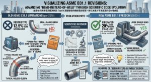
對於 P91/P92 等潛變強度增強型鐵素體鋼(P-No. 15E),高達 20% 的塑性應變曾被視為工程禁忌,因其會產生巨量晶格缺陷,破壞回火麻田散鐵基體,導致材料的潛變延展性呈現斷崖式下降。然而,最新版 ASME B31.1(Table 129.3.3.1-1)明確規範,當冷作應變率超過 5% 時,只要依法強制執行精確的彎後熱處理(PBHT),即可將應變率極限值合法放寬至 20%。 For Creep-Strength-Enhanced Ferritic Steels like P91/P92 (P-No. 15E), a plastic strain of up to 20% was once considered an engineering taboo because it would generate massive lattice defects, destroy the tempered martensite matrix, and cause the material’s creep ductility to drop off a cliff. However, the latest ASME B31.1 (Table 129.3.3.1-1) explicitly specifies that when the cold work strain rate exceeds 5%, as long as a precise Post-Bend Heat Treatment (PBHT) is mandatorily executed according to the code, the strain rate limit can be legally relaxed to 20%.
為符合這項嚴格的法規門檻,潁璋工程導入了極致的「單管感應亞臨界彎後熱處理(IH-PBHT)」。IH-PBHT 的核心冶金技術在於:將高頻感應加熱的目標溫度嚴密鎖定在材料的下臨界溫度(AC1,約 810°C)之下,完全契合規範要求的 730°C 至 770°C 回火區間。 To meet this strict regulatory threshold, Ying-Zhang Engineering introduced the ultimate “Induction Heating Subcritical Post-Bend Heat Treatment (IH-PBHT).” The core metallurgical technology of IH-PBHT lies in strictly locking the target temperature of high-frequency induction heating below the material’s lower critical temperature (AC1 , approx. 810°C), perfectly aligning with the tempering range of 730°C to 770°C required by the code.
在此「亞臨界(Subcritical)」條件下,材料不會發生重新沃斯田鐵化(Re-austenitizing)的相變異,而是啟動了深度的回復機制:Under these “Subcritical” conditions, the material does not undergo Re-austenitizing phase transformation; instead, a deep recovery mechanism is initiated:
- 無溫差釋放殘餘應力:感應渦電流由內而外均勻加熱,消除冷作加工硬化。Temperature-gradient-free residual stress relief: Induction eddy currents heat uniformly from the inside out, eliminating cold work strain hardening.
- 組織穩定化與抗潛變確保:精準的熱能促使高密度差排攀移重組,同時完美保留了 P91 的回火麻田散鐵基體與負責釘扎差排的 MX 碳氮化物析出相,確保其不被粗化。
Microstructural stabilization and creep resistance assurance: Precise thermal energy promotes the climb and rearrangement of high-density dislocations, while perfectly preserving the tempered martensite matrix of P91 and the MX carbonitride precipitates responsible for pinning dislocations, ensuring they do not coarsen.
這一程序的落實,完美滿足了 ASME B31.1 Table 129.3.3.1-1 的規範要求,賦予了 3D/5D 大半徑冷作彎管在極端高壓蒸汽管線上全面取代銲接彎頭的法理基礎與冶金信心。 The implementation of this procedure perfectly meets the requirements of ASME B31.1 Table 129.3.3.1-1, granting 3D/5D large-radius cold bends the legal foundation and metallurgical confidence to comprehensively replace welded elbows on extreme high-pressure steam pipelines.
5.8 2026版 ASME B31J 強制導入下 1.0D/1.5D 銲接彎頭與 3D/5D 冷作彎管之實務工法差異分析 / 5.8 Practical Method Difference Analysis between 1.0D/1.5D Welded Elbows and 3D/5D Cold Bends under the Mandatory Introduction of 2026 ASME B31J
在 2026 年版 ASME B31J 全面強制導入的法規框架下,管線系統中的轉向元件面臨了前所未有的嚴苛檢驗。工程實務上,針對 1.0D 套銲彎頭(Socket-welded elbows)、1.5D 對銲彎頭(Butt-welded elbows)與 3D/5D 數控冷作彎管(CNC Cold Bends)的選擇,在力學表現、冶金風險與製造成本上產生了顯著的分野。Under the regulatory framework of the comprehensive mandatory introduction of the 2026 edition of ASME B31J, directional components in piping systems face unprecedentedly severe inspections. In engineering practice, the choice between 1.0D Socket-welded elbows, 1.5D Butt-welded elbows, and 3D/5D CNC Cold Bends yields significant divergences in mechanical performance, metallurgical risks, and manufacturing costs.
一、 應力強度因子(SIF)解耦與截面橢圓化(Ovalization)之差異 / 1. Differences in SIF Decoupling and Section Ovalization
在舊版 Appendix D 時代,工程設計往往仰賴單一標量的 Markl 疲勞方程式(即 iSa=245,000N-0.2),嚴重低估了短半徑彎頭在複雜環境下的應力集中現象1。ASME B31J 引入三維空間應力解耦矩陣後,1.0D 與 1.5D 銲接彎頭在面外應力(Out-of-plane, io)與扭轉應力(Torsional, it)層面上經常浮現嚴重的超標窘境。其根本物理原因在於柔性特徵值(Flexibility Characteristic, h=T⋅R1/r22)的先天限制;1.0D/1.5D 彎頭的彎曲中心半徑(R1)極小,導致 h 值偏低。當承受熱膨脹交變彎矩時,短半徑彎頭的頂側(Crowns)會發生劇烈的橫截面橢圓化畸變,進而導致剛度退化與局部應力集中2。 In the era of the old Appendix D, engineering design often relied on the single-scalar Markl fatigue equation (i.e., iSa=245,000N-0.2), severely underestimating the stress concentration phenomena of short-radius elbows under complex environments1. After ASME B31J introduced the three-dimensional stress decoupling matrix, 1.0D and 1.5D welded elbows frequently exhibited severe limit-exceeding dilemmas in Out-of-plane (io) and Torsional (it) stress aspects. The fundamental physical reason lies in the inherent limitation of the Flexibility Characteristic (h=T⋅R1/r22); the bend centerline radius (R1) of 1.0D/1.5D elbows is extremely small, resulting in a low h value. When subjected to thermal expansion alternating bending moments, the Crowns of short-radius elbows undergo drastic cross-sectional ovalization distortion, thereby leading to stiffness degradation and local stress concentration2.
相對而言,若採用 5D 大半徑冷作彎管,其 R1 實質放大了 3.3 倍以上,使得 h 值呈線性倍增。這賦予了管件極強的截面穩定性,能有效抵抗外在彎矩引發的幾何畸變,使其 SIF 數值大幅衰減,甚至逼近於完美直管的 1.01。 Comparatively, if 5D large-radius cold bends are used, their R1 is substantially magnified by over 3.3 times, causing the h value to multiply linearly. This grants the component extremely strong cross-sectional stability, capable of effectively resisting geometric distortion triggered by external bending moments, causing its SIF values to decay significantly, even approaching the 1.0 of a perfect straight pipe1.
二、 銲接熱影響區(HAZ)與流體力學損害 / 2. Weld Heat-Affected Zone (HAZ) and Fluid Mechanical Damage
1.0D 套銲彎頭與 1.5D 對銲彎頭無可避免地會在其端點引入銲接熱影響區(HAZ)。在 CCPP 的高溫高壓環境中,材料的細晶區(FGHAZ)與臨界間區(ICHAZ)極易發生 Type IV 潛變開裂2。同時,依照 ASME B31.1 Table 136.4 的嚴格規範,此類處於潛變區間運行的受壓銲縫,必須執行高強度的表面(PT/MT)與 100% 體積(RT/UT)非破壞檢測,大幅墊高了現場施工與檢驗成本3。 1.0D socket-welded elbows and 1.5D butt-welded elbows inevitably introduce Weld Heat-Affected Zones (HAZ) at their ends. In the high-temperature and high-pressure environment of CCPP, the Fine-Grained HAZ (FGHAZ) and Intercritical HAZ (ICHAZ) of the material are highly susceptible to Type IV creep cracking2. At the same time, according to the strict regulations of ASME B31.1 Table 136.4, such pressure-retaining welds operating in the creep regime must undergo high-intensity surface (PT/MT) and 100% volumetric (RT/UT) Non-Destructive Examinations, substantially driving up on-site construction and inspection costs3.
在流體力學方面,1.0D/1.5D 的急彎幾何會引發劇烈的邊界層剝離;而 5D 冷作彎管則因平滑曲率,可使二次流強度(迪安數,Dean Number)大幅衰減,消除流體加速腐蝕(FAC)的風險,並降低 20% 至 30% 的系統局部壓降2。 In terms of fluid mechanics, the sharp bend geometry of 1.0D/1.5D induces severe boundary layer separation; whereas 5D cold bends, due to their smooth curvature, can substantially attenuate secondary flow intensity (Dean Number), eliminate the risk of Flow-Accelerated Corrosion (FAC), and reduce system local pressure drops by 20% to 30%2.
三、 製造品管與壁厚餘裕之經濟考量 / 3. Economic Considerations of Manufacturing Quality Control and Wall Thickness Margin
在導入冷作彎管工法時,必須依循 ASME B16.49 等製造標準控制品質。5D 冷作彎管的局部減薄率較低,實務上僅需預留約 14% 的壁厚餘裕(1.14tm);但若採用 3D 冷作彎管,減薄率急劇上升,需預留高達 25% 的餘裕(1.25tm)。這將迫使 EPC 團隊採購特製的超厚母管,不僅增加材料成本,更會加重管架支撐系統的力學荷重1。因此,5D 彎管在經濟與力學上取得了最佳平衡。在成型後,為消除約 10.0% 的微觀晶格應變,5D 彎管必須強制執行 705°C 至 760°C 的次臨界感應加熱彎後熱處理(IH-PBHT),確保其橢圓度(彎管本體 ≦ 3%,直管切線區 ≦ 1%)與微觀硬度完全合規,保障長期的潛變韌性1。 When introducing the cold bending method, quality must be controlled following manufacturing standards such as ASME B16.49. The localized thinning rate of 5D cold bends is relatively low, practically requiring only about a 14% wall thickness margin (1.14tm); however, if 3D cold bends are used, the thinning rate rises sharply, requiring a margin of up to 25% (1.25tm). This forces EPC teams to procure specially made extra-heavy parent pipes, which not only increases material costs but also exacerbates the mechanical load on the pipe support system1. Therefore, 5D bends achieve the best balance economically and mechanically. After forming, to eliminate approximately 10.0% of micro-lattice strain, 5D bends must undergo a mandatory Subcritical Induction Heating Post-Bend Heat Treatment (IH-PBHT) at 705°C to 760°C to ensure their ovality (≦ 3% in the bend body, ≦ 1% in the straight tangent sections) and micro-hardness are fully compliant, safeguarding long-term creep toughness1.
六、 結論 / VI. Conclusion
ASME B31J 的強制導入與傳統 Appendix D 經驗公式的徹底廢除,象徵著工業管線應力工程正式從粗略的經驗法則邁向高精度數值分析的典範轉移。在 B31.1 與 B31.3 雙重視角的規範框架下,B31J 透過將應力增強係數(SIF)與持續應力指數(SSI)在多個自由度上的徹底解耦,一方面消除了將靜力崩塌與動態疲勞混為一談的盲目保守,另一方面卻也如實揭露了薄壁支管與複雜幾何管件在熱循環服役下的致命脆弱點。The mandatory introduction of ASME B31J and the complete abolition of the traditional Appendix D empirical formulas symbolize the formal paradigm shift of industrial piping stress engineering from rough rules of thumb to high-precision numerical analysis. Under the dual strict regulatory framework of B31.1 and B31.3, B31J, by thoroughly decoupling the Stress Intensification Factor (SIF) and Sustained Stress Index (SSI) across multiple degrees of freedom, eliminates the blind conservatism of conflating static collapse with dynamic fatigue on one hand, while faithfully exposing the fatal vulnerabilities of thin-walled branch pipes and complex geometric components under thermal cycling service on the other.
本研究證實,面對現代 CCPP 電廠與先進石化工廠因頻繁啟停所引發的低週期熱疲勞與潛變破裂挑戰,傳統依賴增設剛性支撐架或採用 1.5D 短半徑銲接彎頭的常規手段已捉襟見肘。這些舊有策略不僅受限於工廠空間足跡與敏感設備管嘴載荷的極限,更無法從根本上解決銲接熱影響區(尤其是 FGHAZ)固有的材質劣化與彎頭急彎導致的流體加速腐蝕(FAC)問題。This study confirms that facing the challenges of low-cycle thermal fatigue and creep rupture triggered by frequent startups and shutdowns in modern CCPP and advanced petrochemical plants, traditional conventional methods relying on adding rigid supports or using 1.5D short-radius welded elbows have fallen short. These old strategies are not only restricted by the limits of plant spatial footprints and sensitive equipment nozzle loads, but they also fundamentally fail to resolve the inherent material degradation in the weld Heat-Affected Zones (especially FGHAZ) and the Flow-Accelerated Corrosion (FAC) problems caused by sharp elbow bends.
ASME B31.1 最新規範將冷作應變率放寬至 20% 的科學修訂,為「能彎不銲(Bend-instead-of-weld)」的先進設計理念提供了堅若磐石的法源依據。潁璋工程(Ying-Zhang Engineering)所提出的「三合一工法」——深度整合 3D/5D CNC 大半徑冷作彎管、IH-PBHT 單管感應亞臨界彎後熱處理以及 QR Code 數位履歷——被證明是應對此一工程挑戰的終極解方。3D/5D 彎管大幅平滑化了幾何應力分佈(使 SIF 趨近於 1.0),而 IH-PBHT 精確地在亞臨界溫度下消除了冷作加工硬化,完美確保了 P91/P92 等高階材料顯微組織的長效穩定性;最終,數位履歷構築了數位孿生的資料基盤,達成了預測性維護的全生命週期目標。這一高度整合的力學與冶金策略,不僅完全契合了 2026 年版 ASME 規範對高能管線在極端環境下的安全要求,更為未來工業重金屬管線的設計與營運管理,樹立了難以超越的工程標竿。The scientific revision in the latest ASME B31.1 code to relax the cold work strain rate to 20% provides a rock-solid legal basis for the advanced design philosophy of “Bend-instead-of-weld.” The “Three-in-One Method” proposed by Ying-Zhang Engineering—deeply integrating 3D/5D CNC large-radius cold bending, IH-PBHT single-pipe induction subcritical post-bend heat treatment, and QR Code digital traceability—is proven to be the ultimate solution to address this engineering challenge. 3D/5D bends vastly smooth out geometric stress distribution (bringing SIF close to 1.0), and IH-PBHT precisely eliminates cold work strain hardening at subcritical temperatures, perfectly ensuring the long-term microstructural stability of high-end materials like P91/P92. Ultimately, the digital traceability builds a data foundation for the Digital Twin, achieving the life-cycle goal of predictive maintenance. This highly integrated mechanical and metallurgical strategy not only fully complies with the safety requirements of the 2026 ASME codes for high-energy piping in extreme environments but also sets an insurmountable engineering benchmark for the design and operational management of future heavy industrial metal piping.
參考文獻 / References
- https://yz-pipe-bending.com.tw/%E5%9F%BA%E6%96%BC-2026-asme-b31j-%E8%A6%8F%E7%AF%84%E4%B9%8B%E5%A4%A7%E5%9E%8B-ccpp-%E5%B0%88%E6%A1%88%E7%AE%A1%E7%B7%9A%E5%B7%A5%E6%B3%95%E5%84%AA%E5%8C%96%EF%BC%9Aepc-%E4%BB%8B%E9%9D%A2%E5%8D%94/
- https://yz-pipe-bending.com.tw/%E5%9F%BA%E6%96%BC-asme-b31j-%E8%A6%8F%E7%AF%84%E4%B9%8B%E9%9B%BB%E5%BB%A0%E9%AB%98%E8%83%BD%E7%AE%A1%E7%B7%9A%E9%A0%90%E8%A3%BD%E5%B7%A5%E6%B3%95%E6%9C%80%E4%BD%B3%E5%8C%96%EF%BC%9A%E5%A4%A7%E5%8D%8A/
- ASME B31.1 NDE Requirements Summary | PDF – Scribd, https://www.scribd.com/document/451530663/tabla-asme-b31-1