
一、 緒論 / 1. Introduction
在當代先進的超臨界(Supercritical, SC)與超超臨界(Ultra-supercritical, USC)火力發電廠以及新世代核能發電設施中,高能管線系統(High-Energy Piping Systems)無疑是整座電廠的運作動脈,持續承受著極端的高溫與高壓操作條件。為因應全球對熱效率提升與碳排放降低的迫切需求,主蒸汽與再熱蒸汽的溫度及壓力標準不斷突破物理極限,這直接推動了新型抗潛變鋼材的研發與廣泛應用。其中,P9x系列鋼材(涵蓋P91、P92等改質9Cr-1Mo鐵素體-麻田散體耐熱鋼)憑藉其在高於 500°C 環境下所展現的卓越潛變強度(Creep Strength)與抗高溫氧化性能,已全面取代傳統的P22低合金鋼材,成為當今業界的基準材料1。P9x鋼材所具備的高許用應力,使工程師得以在維持相同壓力等級的前提下大幅縮減管壁厚度。這種薄壁化設計不僅有效降低了管線系統的總重量,減輕了支撐結構的負擔,更大幅降低了管壁內的熱慣性與熱應力梯度,從而縮短大型發電機組在冷啟動與熱啟動過程中的時間消耗1。 In contemporary advanced Supercritical (SC) and Ultra-supercritical (USC) thermal power plants, as well as next-generation nuclear power facilities, High-Energy Piping Systems are undeniably the operational arteries of the entire plant, continuously withstanding extreme high-temperature and high-pressure conditions. Driven by the urgent global demand for improved thermal efficiency and reduced carbon emissions, the temperature and pressure standards for main steam and reheat steam continue to break physical limits, directly propelling the development and widespread application of new creep-resistant steels. Among them, the P9x series of steels (including modified 9Cr-1Mo ferritic-martensitic heat-resistant steels such as P91 and P92) have completely replaced traditional P22 low-alloy steels, becoming the benchmark material in the industry today due to their outstanding creep strength and high-temperature oxidation resistance in environments above 500°C1. The high allowable stress of P9x steels enables engineers to significantly reduce the pipe wall thickness while maintaining the same pressure rating. This thin-wall design not only effectively reduces the total weight of the piping system and lightens the load on support structures, but also substantially lowers thermal inertia and thermal stress gradients within the pipe wall, thereby shortening the time consumed during cold and hot startups of large generating units1.
然而,P9x鋼材雖然在材料科學領域取得了巨大成功,但其對於熱加工循環、幾何不連續性以及應力集中現象卻極度敏感。在現場實際的管線對接銲接施工中,管內壁的微小幾何缺陷——尤其是內外錯邊(High-Low Misalignment)與內突銲道 / 銲根下垂(Root Sag / Excess Penetration)——往往成為觸發管線早期災難性失效的致命隱患。這些位於管線內部、難以透過常規外部檢測輕易察覺的根部缺陷,在長期承受高溫潛變與反覆熱循環疲勞(Creep-Fatigue Interaction, CFI)的嚴苛交變應力環境下,會產生極高的局部三軸應力集中,進而誘發微觀孔洞(Micro-voids)的成核與延展,最終演變為貫穿管壁的巨觀裂紋2。 However, despite the immense success of P9x steels in the field of materials science, they are extremely sensitive to thermal processing cycles, geometric discontinuities, and stress concentration phenomena. During actual on-site butt welding of piping, minor geometric defects on the inner pipe wall—especially internal/external high-low misalignment and root sag (excess root penetration)—often become fatal hidden dangers that trigger premature, catastrophic failures of the piping. These root defects, located inside the pipe and difficult to detect easily through conventional external inspections, generate extremely high local triaxial stress concentrations when subjected to the severe alternating stress environments of long-term high-temperature creep and repeated creep-fatigue interaction (CFI). This in turn induces the nucleation and propagation of micro-voids, eventually evolving into macroscopic cracks that penetrate the pipe wall2.
本研究報告將系統性地深入剖析P9x高能管線銲接過程中,內外錯邊與內突銲道的生成物理機制、流體力學成因及其對結構完整性的深遠影響。本報告的範疇涵蓋材料的物理冶金相變特性、局部應力集中的固體力學效應,以及潛變-疲勞損傷的微觀機制。同時,本報告將針對國際上具權威性之銲接施工驗收標準——包含ASME B31.1(動力管線規範)、ASME B31.3(製程管線規範)以及ISO 5817(銲接品質等級)——進行全面且細緻的交叉比對與檢討,探討不同工程法規在風險管理哲學與容忍極限值上的根本差異。此外,亦將整合 2026 年版 ASME B31J 規範的強制導入趨勢,探討冷作彎管工法與傳統銲接彎頭的實務差異,並據此提出對應之高品質施工控制與預防策略,以確保高能管線系統的長期運轉安全。This research report will systematically and deeply analyze the physical mechanisms, fluid dynamics causes, and profound impacts on structural integrity of high-low misalignment and excess root penetration during the welding process of P9x high-energy piping. The scope of this report covers the physical metallurgical phase transformation characteristics of the material, the solid mechanics effects of local stress concentration, and the microscopic mechanisms of creep-fatigue damage. Simultaneously, this report will conduct a comprehensive and detailed cross-comparison and review of authoritative international welding acceptance standards—including ASME B31.1 (Power Piping), ASME B31.3 (Process Piping), and ISO 5817 (Welding Quality Levels)—exploring the fundamental differences in risk management philosophies and tolerance limits among various engineering codes. Furthermore, by integrating the mandatory implementation trend of the 2026 edition of the ASME B31J code, this report will examine the practical differences between the cold-formed bending method and traditional welded elbows, proposing corresponding high-quality construction control and preventive strategies to ensure the long-term safe operation of high-energy piping systems.
二、 P9x高能管線之冶金相變特性與環境敏感度分析 / 2. Metallurgical Phase Transformation Characteristics and Environmental Sensitivity of P9x High-Energy Piping
要深刻理解幾何缺陷對P9x管線所造成的巨大威脅,必須首先從微觀層面掌握該材料極為特殊的冶金特性。P91(Grade 91)與P92(Grade 92)鋼材之所以具備卓越的高溫潛變抗力,主要歸功於其精確調控的微量合金元素與極為嚴謹的煉鋼及熱處理製程。在基礎的 9% 鉻與 1% 鉬成分上,P9x合金精準添加了釩(V)、鈮(Nb)與氮(N)等微量元素。這些元素在經過正火與回火處理後的麻田散體基質(Martensitic Matrix)中,會析出極度微細且熱力學穩定的碳氮化物(例如微米級的M23C6型碳化物與奈米級的MX型碳氮化物)。這些析出物沿著原沃斯田鐵晶界與麻田散體板條邊界均勻分佈,透過釘扎差排(Pinning Dislocations)與抑制亞晶界滑移的機制,提供了強大且持久的高溫潛變抗性1。 To deeply understand the immense threat posed by geometric defects to P9x piping, one must first grasp the highly specific metallurgical characteristics of the material at a microscopic level. The reason P91 (Grade 91) and P92 (Grade 92) steels possess exceptional high-temperature creep resistance is primarily due to their precisely controlled trace alloying elements and extremely rigorous steelmaking and heat treatment processes. Building on a base of 9% chromium and 1% molybdenum, P9x alloys are precisely doped with trace elements such as vanadium (V), niobium (Nb), and nitrogen (N). In the martensitic matrix formed after normalizing and tempering treatments, these elements precipitate extremely fine and thermodynamically stable carbonitrides (e.g., micrometer-scale M23C6-type carbides and nanometer-scale MX-type carbonitrides). These precipitates are uniformly distributed along the prior austenite grain boundaries and martensitic lath boundaries, providing powerful and long-lasting high-temperature creep resistance through mechanisms of pinning dislocations and suppressing sub-grain boundary sliding1.
2.1 銲接熱循環下之相變行為與未回火麻田散體之生成 / 2.1 Phase Transformation Behavior Under Welding Thermal Cycles and Generation of Untempered Martensite
P9x鋼材在工廠預製與現場銲接施工中所面臨的最大冶金挑戰,在於其極端的高硬化傾向。當銲接熱輸入導致熱影響區(HAZ)的局部溫度超越材料的AC3 上臨界相變溫度時,該區域的微觀組織會完全沃斯田鐵化(Austenitization),並伴隨著原有強化析出物的粗化或部分溶解2。在隨後的銲道冷卻過程中,由於材料含有豐富的鉻與鉬,其臨界冷卻速率極低,因此即使在靜止空氣中緩慢冷卻,沃斯田鐵也極易發生無擴散相變,轉變為堅硬、極脆且內部充滿高度殘餘應力的未回火麻田散體(Untempered Martensite)1。 The greatest metallurgical challenge faced by P9x steels during shop fabrication and on-site welding lies in their extreme hardening tendency. When the welding heat input causes the local temperature in the heat-affected zone (HAZ) to exceed the material’s AC3 upper critical phase transformation temperature, the microstructure in this region becomes fully austenitized, accompanied by the coarsening or partial dissolution of the original strengthening precipitates2. During the subsequent cooling of the weld, because the material is rich in chromium and molybdenum, its critical cooling rate is extremely low. Thus, even with slow cooling in still air, the austenite easily undergoes a diffusionless phase transformation, converting into untempered martensite, which is hard, extremely brittle, and filled with high residual stress1.
未回火麻田散體的生成,大幅降低了該區域的破裂韌性,使其對任何形式的應力集中或外來缺陷極度敏感。如果在此時管線根部存在由錯邊或銲根下垂所構成的幾何銳角,該處的幾何不連續性將成為應力放大的集中點,任何輕微的機械震動或熱應力波動,皆可能導致脆性微裂紋的瞬間萌生與擴展1。 The generation of untempered martensite drastically reduces the fracture toughness in this region, making it extremely sensitive to any form of stress concentration or external defects. If a sharp geometric angle caused by misalignment or root sag exists at the pipe root at this time, the geometric discontinuity at that location will become a focal point for stress amplification. Any slight mechanical vibration or thermal stress fluctuation could lead to the instantaneous initiation and propagation of brittle micro-cracks1.
2.2 氫致冷裂敏感性與背面充氣保護之絕對必要性 / 2.2 Hydrogen-Assisted Cold Cracking Sensitivity and the Absolute Necessity of Back Purging
伴隨未回火麻田散體而來的另一項致命威脅,是氫致冷裂(Hydrogen-Assisted Cold Cracking, HACC)。P9x銲縫與熱影響區對擴散性氫(Diffusible Hydrogen)具有極高的捕捉與敏化能力10。在氣體鎢弧銲(GTAW)或被覆金屬電弧銲(SMAW)過程中,若銲材未經徹底烘焙(實務上多要求採用 H4 等級,即每 100 克熔敷金屬中擴散氫含量小於 4 毫升的極低氫銲條),或管線根部缺乏嚴密的惰性氣體保護,高溫電弧會輕易將環境中的水氣解離為原子氫。這些體積極小的氫原子會迅速溶入液態熔池,並在冷卻過程中向晶界、差排網以及應力集中區域擴散並富集7。 Another fatal threat accompanying untempered martensite is Hydrogen-Assisted Cold Cracking (HACC). P9x welds and HAZs possess an extremely high trapping and sensitization capacity for diffusible hydrogen10. During Gas Tungsten Arc Welding (GTAW) or Shielded Metal Arc Welding (SMAW), if the welding consumables are not thoroughly baked (in practice, H4 designation is often required, meaning extremely low-hydrogen electrodes with less than 4 ml of diffusible hydrogen per 100 grams of deposited metal), or if the pipe root lacks strict inert gas protection, the high-temperature arc will easily dissociate moisture from the environment into atomic hydrogen. These tiny hydrogen atoms will rapidly dissolve into the liquid weld pool and, during cooling, diffuse and concentrate at grain boundaries, dislocation networks, and stress concentration zones7.
研究數據明確顯示,一旦擴散性氫在錯邊或下垂根部這類高應力區域累積超越臨界濃度,氫原子會顯著降低晶界的內聚力,誘發延遲性的沿晶破裂。此外,P9x鋼材的高鉻含量使其在缺乏氧氣隔離的高溫下極易發生嚴重氧化。因此,針對P9x管線的打底層與熱銲層(Hot pass)施工,國際規範強制要求必須在管內施加 100% 純氬氣(Argon)的背面充氣保護(Back Purging),確保管內氧氣含量降至百萬分之一(ppm)等級7。背壓氣體的控制也是一門極其細緻的流體力學技術:背壓過低無法有效排氣與防止氧化;背壓過高則會將液態熔融金屬向外推擠,形成內凹缺陷;而在壓力控制不穩定的情況下,熔池失去支撐,便會重力下墜形成嚴重的內突銲道13。 Research data clearly shows that once diffusible hydrogen accumulates beyond a critical concentration in high-stress areas such as misaligned or sagging roots, the hydrogen atoms will significantly reduce grain boundary cohesion, inducing delayed intergranular cracking. Furthermore, the high chromium content of P9x steels makes them highly susceptible to severe oxidation at elevated temperatures without oxygen isolation. Therefore, for root pass and hot pass welding of P9x piping, international standards mandate the application of 100% pure argon back purging inside the pipe, ensuring internal oxygen levels are reduced to parts per million (ppm) levels7. Controlling the backing gas pressure is also an extremely delicate fluid dynamics technique: insufficient back pressure fails to effectively purge air and prevent oxidation; excessive back pressure pushes the liquid molten metal outward, forming root concavity defects; and under unstable pressure control, the weld pool loses support and sags due to gravity, forming severe excess root penetration13.
2.3 臨界熱控制:預熱、層間溫度與去氫熱處理 / 2.3 Critical Thermal Control: Preheat, Interpass Temperature, and Dehydrogenation Heat Treatment
為防範氫致裂紋與脆性斷裂,嚴格的溫度控制是銲接P9x鋼材的核心解答。ASME B31.1與ASME Section I等法規強制規定,對於厚度大於 13 mm 的P9x鋼材,在點銲與正式銲接前的最低預熱溫度絕對不可低於 204°C (400°F)1。任何在室溫下進行的無預熱搭橋定位銲(Bridge tacking),皆會立即生成氫裂紋的起始源。 To prevent hydrogen-induced cracking and brittle fracture, strict temperature control is the core answer to welding P9x steels. Codes such as ASME B31.1 and ASME Section I mandate that for P9x steels thicker than 13 mm, the minimum preheat temperature prior to tack welding and formal welding must absolutely not be lower than 204°C (400°F)1. Any bridge tacking performed at room temperature without preheat will immediately generate initiation sites for hydrogen cracks.
在銲接過程中,層間溫度(Interpass Temperature)必須嚴格限制在 350°C 以下。這項上限設計的冶金意義在於,確保每一道銲層在被後續銲層覆蓋前,其溫度能夠下降至麻田散體變態開始溫度(Ms)以下,促使該層金屬發生部分相變。如此一來,後續銲層的熱輸入便能對前一層已變態的麻田散體產生原位回火效應(In-situ Tempering),從而降低整體應力與硬度1。 During the welding process, the interpass temperature must be strictly limited to below 350°C. The metallurgical significance of this upper limit is to ensure that each weld layer cools below the martensite start temperature (Ms) before being covered by the subsequent layer, promoting partial phase transformation in that metal layer. In doing so, the heat input from the subsequent weld layer acts as an in-situ tempering effect on the already transformed martensite of the previous layer, thereby reducing overall stress and hardness1.
銲接完成後,嚴禁將管線直接冷卻至室溫。施工團隊必須立即實施去氫熱處理(Dehydrogenation Heat Treatment, DHT)或氫釋放烘烤(Hydrogen Bake-out),將溫度維持在 300°C 至 350°C 之間並保溫數小時,以驅動殘留的原子氫擴散逸出金屬晶格1。隨後,管線必須在隔熱毯包覆下,極其緩慢地冷卻至麻田散體變態完成溫度(Mf,約 96°C)以下。這一步驟至關重要,若未冷卻至 96°C 以下即開始進行高溫銲後熱處理(PWHT),組織中將殘留不穩定的沃斯田鐵,這些殘留沃斯田鐵在 PWHT 冷卻後會再次轉變為未回火麻田散體,徹底摧毀接頭的潛變韌性1。最終的 PWHT 溫度設定,必須依據具體銲材批次的錳加鎳(Mn+Ni)實際總量進行動態調整,通常控制在 740°C 至 760°C 之間,以避免超過下臨界溫度 AC1 而引發災難性的重新沃斯田鐵化1。 Upon completion of welding, it is strictly forbidden to cool the piping directly to room temperature. The construction team must immediately implement a Dehydrogenation Heat Treatment (DHT) or hydrogen bake-out, maintaining the temperature between 300°C and 350°C for several hours to drive residual atomic hydrogen to diffuse out of the metal lattice1. Subsequently, wrapped in insulating blankets, the piping must be cooled extremely slowly to below the martensite finish temperature (Mf, approximately 96°C). This step is crucial; if high-temperature Post-Weld Heat Treatment (PWHT) begins before cooling below 96°C, unstable austenite will remain in the microstructure. This retained austenite will transform back into untempered martensite upon cooling after PWHT, completely destroying the creep toughness of the joint1. The final PWHT temperature setting must be dynamically adjusted based on the actual total amount of manganese plus nickel (Mn+Ni) in the specific filler metal batch, typically controlled between 740°C and 760°C, to avoid exceeding the lower critical temperature AC1, which would trigger catastrophic re-austenitization1.
三、 內外錯邊之物理成因與固體力學應力集中效應 / 3. Physical Causes of Internal/External Misalignment and Solid Mechanics Stress Concentration Effects
內外錯邊(Internal/External High-Low Misalignment)是指兩對接管線或管件之內徑與外徑端面未能達成完美的幾何共線對齊,從而在管壁厚度方向上產生了突兀的幾何台階(Offset)。這種現象在高能管線的現場佈建中幾乎無法完全避免,但其對P9x材料壽命的破壞力卻是毀滅性的17。 Internal/External High-Low Misalignment refers to the failure of the inner and outer diameter end faces of two mating pipes or fittings to achieve perfect geometric collinear alignment, thereby creating an abrupt geometric offset in the thickness direction of the pipe wall. This phenomenon is almost unavoidable during the field layout of high-energy piping, yet its destructive impact on the lifespan of P9x materials is devastating17.
3.1 錯邊生成之幾何公差與製程淵源 / 3.1 Geometric Tolerances and Manufacturing Origins of Misalignment
錯邊的生成牽涉到多層次的製造與裝配變數。首先,商業級無縫鋼管的製程本質上允許一定範圍的外徑、內徑、壁厚以及真圓度(Out-of-roundness)公差。這意味著即使是標稱規格完全一致的兩根管材,其端面也無法確保 100% 的同心同軸17。其次,在複雜的管線系統中,冷作彎管(Cold Bending)工法被大量運用。根據ASME B31.1與B31.3的規定,冷彎過程會引發管材截面的橢圓化(Flattening)與外弧側的壁厚減薄(Necking Down)。雖然B31.3容許最高達 8% 的橢圓度,但這種幾何變形使得彎管端部與標準直管對接時,必然產生嚴重的內壁錯邊18。 The generation of misalignment involves multi-level manufacturing and assembly variables. Firstly, the manufacturing process of commercial-grade seamless steel pipes inherently allows a certain tolerance range for outer diameter, inner diameter, wall thickness, and out-of-roundness. This means that even two pipes with exactly identical nominal specifications cannot guarantee 100% concentric and coaxial end faces17. Secondly, in complex piping systems, cold bending methods are heavily utilized. According to ASME B31.1 and B31.3 regulations, the cold bending process induces flattening of the pipe cross-section and wall thinning (necking down) on the extrados. Although B31.3 permits a maximum flattening of up to 8%, this geometric deformation inevitably causes severe internal wall misalignment when the bend ends are mated with standard straight pipes18.
進一步言之,當管線系統需連接鍛造閥門、特製鑄件或異徑管件時,端面的壁厚差異更為顯著。若未依照法規要求實施適當的內部機械切削加工(Counterboring)或削度過渡(Tapering),直接對接將形成猶如峭壁般的應力阻礙17。最後,現場裝配(Fit-up)時的定位工裝夾持精度不足,或為了彌補配管長度誤差而強行施加冷拉力(Cold Springing),都會在鎖緊定位銲的瞬間鎖入巨大的殘餘應力。這在重視應變控制的製程管線施工中是被嚴格禁止的,因為它不僅惡化了錯邊,更直接增加了一次應力負載17。 Furthermore, when piping systems need to connect forged valves, customized castings, or components of differing diameters, the wall thickness disparity at the end faces is even more pronounced. If appropriate internal counterboring or tapering is not performed according to code requirements, direct butt jointing will form a cliff-like stress barrier17. Lastly, insufficient clamping precision of alignment tooling during on-site fit-up, or the forced application of cold springing to compensate for pipe length errors, will lock in massive residual stresses the moment tack welds are secured. This is strictly prohibited in strain-control-focused process piping construction, as it not only exacerbates misalignment but also directly adds a primary stress load17.
3.2 應力集中之固體力學理論與公式推導 / 3.2 Solid Mechanics Theory and Formula Derivation for Stress Concentration
在力學分析中,錯邊的破壞力源自於其對管壁內部主應力流(Principal Stress Flow)連續性的粗暴切斷。當高能管線在運行中承受高達數十 MPa 的蒸汽內壓,或因溫度梯度引發強烈的軸向熱膨脹推力時,錯邊台階的幾何偏心(Eccentricity)會迫使應力流線在缺陷根部急劇彎折,從而誘發一附加的局部彎矩(Local Bending Moment)4。 In mechanical analysis, the destructive power of misalignment originates from its brutal severing of the continuity of the principal stress flow inside the pipe wall. When high-energy piping sustains internal steam pressures up to tens of MPa during operation, or strong axial thermal expansion thrusts induced by temperature gradients, the geometric eccentricity of the misalignment offset forces the stress flow lines to bend sharply at the root of the defect, thereby inducing an additional local bending moment4.
依據經典殼體理論(Classical Shell Theory)與線性彈性斷裂力學,當一承受均勻軸向名目應力 σnom的圓柱殼體(即管壁)存在厚度方向的軸對稱錯位量 e 時,該錯位處的局部最大應力σmax 可以透過理論應力集中係數(Theoretical Stress Concentration Factor, Kt)來準確量化4。這層力學關係可透過簡化的數學模型表示為: Based on Classical Shell Theory and linear elastic fracture mechanics, when a cylindrical shell (i.e., pipe wall) subjected to a uniform axial nominal stress σnom contains an axisymmetric offset e in the thickness direction, the local maximum stress σmax at the offset can be accurately quantified through the Theoretical Stress Concentration Factor (Kt)4. This mechanical relationship can be represented by a simplified mathematical model:
Kt=1+Ce (e/t)
其中 e 代表絕對錯邊量,t 為較薄側的管壁厚度,Ce 則為取決於邊界條件與錯邊相對位置的應力集中乘數。研究與實驗數據表明,當錯位發生在均勻拉伸的結構中段時,Ce 的理論極限值趨近於 3 4。因此公式可進一步簡化為:where e represents the absolute misalignment value, t is the pipe wall thickness on the thinner side, and Ce is the stress concentration multiplier dependent on boundary conditions and the relative position of the misalignment. Research and experimental data indicate that when the offset occurs in the midsection of a uniformly stretched structure, the theoretical limit of Ce approaches 3 4. Thus, the formula can be further simplified to:
Kt=1+3(e/t)
這項物理公式揭示了一個嚴酷的現實:如果對接管壁的錯邊量達到了厚度的 10%(即 e/t = 0.1),其理論應力集中係數將達到 1.3。這意味著局部應力瞬間飆升至名目應力的 130%。對於普通碳鋼而言,這或許只會導致局部的塑性降伏,材料會透過應變硬化與幾何變形來重新分佈應力;但對於設計在潛變機制下運作的P9x高能管線而言,這額外增加的 30% 應力是致命的。高溫下金屬的穩態潛變速率(Steady-state Creep Rate, ε ̇)遵循 Norton 潛變定律,與施加應力的次方成正比(ε ̇ =Aσn,其中應力指數 n 對於P9x鋼通常介於 4 到 10 之間)3。因此,局部應力若增加 1.3 倍,將導致該區域的潛變速率暴增約 3 倍至 13 倍,其剩餘潛變壽命將隨之呈對數級別的崩塌。 This physical formula reveals a harsh reality: if the misalignment of the butt-welded pipe wall reaches 10% of the thickness (i.e., e/t = 0.1), its theoretical stress concentration factor will reach 1.3. This means the local stress instantly spikes to 130% of the nominal stress. For plain carbon steel, this might only lead to local plastic yielding, as the material redistributes stress through strain hardening and geometric deformation; however, for P9x high-energy piping designed to operate under creep mechanisms, this additional 30% stress is lethal. The steady-state creep rate (ε ̇ ) of metals at high temperatures follows Norton’s creep law, being proportional to a power of the applied stress (ε ̇ =Aσn, where the stress exponent n for P9x steels usually ranges between 4 and 10)3. Therefore, a 1.3-fold increase in local stress will cause the creep rate in that area to surge by roughly 3 to 13 times, resulting in a logarithmic collapse of its remaining creep life.
3.3 缺口敏感度與疲勞缺口係數 (Kf) 轉換 / 3.3 Notch Sensitivity and Fatigue Notch Factor (Kf) Conversion
進一步考慮發電廠在啟動、併網與停機過程中所產生的巨大熱循環負載,這類低週期疲勞(Low-Cycle Fatigue, LCF)負載會與潛變現象疊加。在疲勞分析中,理論應力集中係數 Kt 必須被轉換為更具實際工程意義的疲勞缺口係數(Fatigue Notch Factor, Kf)。兩者的轉換依賴於材料的缺口敏感度指標(Notch Sensitivity Index, q),其關係式為:Further considering the massive thermal cyclic loads generated during the startup, synchronization, and shutdown processes of a power plant, such Low-Cycle Fatigue (LCF) loads superimpose upon the creep phenomenon. In fatigue analysis, the theoretical stress concentration factor Kt must be converted into the more practically meaningful Fatigue Notch Factor (Kf). The conversion between the two relies on the material’s Notch Sensitivity Index (q), expressed by the relationship:
Kf=1+q(Kt-1)
缺口敏感度 q 的值介於 0 與 1 之間,取決於材料的晶格特性與極限抗拉強度(Ultimate Tensile Strength, Sut)。根據材料力學與 Neuber 常數的實證經驗,具有高抗拉強度與降伏強度的合金鋼(如經過回火麻田散體強化的P91鋼),其 q 值極度接近於 1 19。這意味著Kf ≈ Kt。換言之,P9x鋼材對於幾何缺口幾乎不具備任何彈塑性緩衝與應力鬆弛能力,由錯邊引發的理論應力集中效應,會百分之百地轉化為疲勞壽命的折損因子。當缺陷根部的局部應力超過彈性極限時,根據 Neuber 法則(KσKε=Kt2),缺口處的應變集中係數(Kε)將急遽攀升,直接在熱循環中撕裂材料的微觀晶界19。 The value of the notch sensitivity q ranges between 0 and 1, depending on the material’s lattice characteristics and Ultimate Tensile Strength (Sut). Based on solid mechanics and empirical experience with the Neuber constant, alloy steels with high tensile and yield strengths (such as P91 steel strengthened by tempered martensite) exhibit a q value extremely close to 1 19. This implies that Kf ≈ Kt. In other words, P9x steels possess virtually no elastoplastic buffering or stress relaxation capability for geometric notches. The theoretical stress concentration effect induced by misalignment translates 100% into a fatigue life reduction factor. When the local stress at the root of the defect exceeds the elastic limit, according to Neuber’s rule (KσKε=Kt2), the strain concentration factor (Kε) at the notch will rise sharply, directly tearing the material’s microscopic grain boundaries during thermal cycling19.
四、 內突銲道與銲根下垂之熱流體力學與次級破壞效應 / 4. Thermal Fluid Dynamics of Excess Root Penetration (Root Sag) and Secondary Damage Effects
內突銲道(Excess Root Penetration,亦泛稱為銲根下垂 Root Sag),是指在只能進行單面銲接(Single-sided welding)的管線接頭中,根部熔融金屬無法維持在預期的平齊水平,反而過度凸出並垂入管線內部流道的一種幾何缺陷24。對於直徑較小或內部難以進入的高能管線,一旦形成內突銲道,工程上幾乎無法進行內壁的修磨補救,因此從銲接動態控制源頭進行預防顯得無比重要。 Excess Root Penetration (also broadly known as Root Sag) refers to a geometric defect in single-sided welding pipe joints where the molten metal at the root fails to maintain the expected flush level, instead protruding excessively and drooping into the internal flow channel of the pipe24. For high-energy piping with small diameters or inaccessible interiors, once excess root penetration forms, engineering remediation via internal grinding is nearly impossible; hence, prevention from the source through dynamic weld control is of paramount importance.
4.1 銲接熱流體力學與表面張力平衡之破壞 / 4.1 Welding Thermal Fluid Dynamics and the Breakdown of Surface Tension Equilibrium
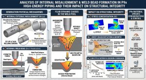
內突銲道的形成機制,深植於高溫熔池內部複雜的熱流體動力學與力學平衡之中。在進行GTAW打底銲接時,懸浮於管線根部間隙之間的液態金屬熔池,無時無刻不受到多重物理向量的拉扯與擠壓。這些力學參數主要包含:促使液態金屬向管內塌陷的重力(Gravity)、來自上方高溫電漿體的電弧吹力(Arc Pressure)、熔池自身的靜水壓力(Hydrostatic Pressure),以及試圖抵抗上述塌陷力量、維持熔池表面平整的液態金屬表面張力(Surface Tension)和由背面充氣保護所提供的背壓(Purge Back-pressure)9。 The formation mechanism of excess root penetration is deeply rooted in the complex thermal fluid dynamics and mechanical equilibrium within the high-temperature weld pool. During GTAW root pass welding, the liquid metal pool suspended across the root gap is constantly subjected to the pulling and squeezing of multiple physical vectors. These mechanical parameters mainly include: Gravity, which drives the liquid metal to collapse into the pipe; Arc Pressure from the high-temperature plasma above; the Hydrostatic Pressure of the weld pool itself; and the opposing forces striving to resist this collapse and maintain surface flatness, namely the liquid metal’s Surface Tension and the Purge Back-pressure provided by the backing gas9.
科學研究指出,當銲接熱輸入(Heat Input)過高,或因操作人員行進速度過慢導致熔池體積與寬度過大時,熔池的幾何尺度將超越表面張力所能負載的臨界半徑。此時,靜水壓力與重力的合力大於表面張力向上的拉伸分量,在重力的無情驅動下,液態金屬便會瞬間向管腔內塌陷,凝固後即形成不可逆的銲根下垂24。此外,裝配參數亦具決定性:若根部間隙(Root Gap)設定過寬(遠超規範建議的 2.0 至 3.5 mm),或鈍邊(Root Face)加工過薄,母材將無法提供足夠的熱傳導散熱路徑與機械支撐力,導致熔池邊界無法迅速凝固,進一步惡化下墜的幅度1。 Scientific research indicates that when the welding Heat Input is too high, or when the weld pool volume and width become excessively large due to the operator’s slow travel speed, the geometric scale of the weld pool will exceed the critical radius that surface tension can support. At this point, the combined force of hydrostatic pressure and gravity exceeds the upward tensile component of the surface tension. Driven mercilessly by gravity, the liquid metal instantly collapses into the pipe cavity, forming irreversible root sag upon solidification24. In addition, fit-up parameters are decisive: if the Root Gap is set too wide (far exceeding the code-recommended 2.0 to 3.5 mm), or if the Root Face is machined too thin, the base metal will fail to provide adequate thermal conduction paths and mechanical support. This prevents the weld pool boundary from solidifying rapidly, further exacerbating the extent of the sag1.
4.2 內突銲道對流場與管壁完整性之次級危害效應 / 4.2 Secondary Hazard Effects of Excess Root Penetration on Flow Field and Pipe Wall Integrity
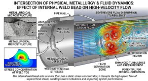
在物理冶金與流體動力學的交集層面,內突銲道絕對不僅僅是一個靜態的應力集中點,它更會對管內高速流動的介質(如高溫高壓超臨界蒸汽)產生極為嚴重的擾流作用(Flow Disruption)。
At the intersection of physical metallurgy and fluid dynamics, excess root penetration is absolutely not merely a static stress concentration point; rather, it produces severe flow disruption on the high-speed flowing medium (such as high-temperature, high-pressure supercritical steam) inside the pipe.
第一層次的物理危害,展現於流體動力學所引發的沖刷腐蝕(Erosion-Corrosion)。在超臨界狀態下運行的蒸汽,具有極高的動能並可能夾帶微小水滴或脫落的氧化皮雜質。當這股高速洪流撞擊到管壁上突出的銲根時,會在其後方產生劇烈的渦流(Vortex)與局部負壓區。持續的物理衝擊與空穴效應(Cavitation)會迅速剝離P9x鋼材表面原本能抵抗高溫的緻密富鉻氧化物保護層,將新鮮的基材直接暴露於高溫氧化環境中,導致該局部管壁厚度加速減薄24。 The first level of physical hazard manifests as Erosion-Corrosion induced by fluid dynamics. Steam operating in a supercritical state possesses extremely high kinetic energy and may entrain tiny water droplets or spalled oxide scale impurities. When this high-speed torrent impacts the protruding root on the pipe wall, it generates violent vortices and localized negative pressure zones downstream. The continuous physical impact and cavitation effects rapidly strip away the dense chromium-rich oxide protective layer on the P9x steel surface—which originally resists high temperatures—directly exposing fresh base material to a high-temperature oxidative environment, resulting in accelerated localized thinning of the pipe wall24.
第二層次的危害則回歸到結構力學本質。局部的流體沖刷減薄,不可避免地增加了該區域的膜應力(Membrane Stress);更為致命的是,內突銲道本身與母材內壁交界處(Weld Toe)形成了一個不規則且銳利的幾何凹角。這個交界處的應力集中效應,同樣適用前述的 Kt 理論,且由於銲道邊緣的曲率半徑通常極小,其局部應力梯度甚至比平緩的錯邊更為險惡19。在高溫與循環應力的催化下,這個微小的幾何突變點,往往成為疲勞微裂紋向管線外壁呈放射狀擴展的最早起源。 The second level of hazard returns to the essence of structural mechanics. Localized fluid erosive thinning inevitably increases the Membrane Stress in that region. Even more fatally, the junction between the excess root penetration itself and the inner wall of the base metal (the Weld Toe) forms an irregular and sharp geometric re-entrant angle. The stress concentration effect at this junction equally obeys the aforementioned Kt theory, and because the radius of curvature at the weld edge is typically extremely small, its local stress gradient is even more treacherous than that of a mild misalignment19. Catalyzed by high temperatures and cyclic stresses, this minuscule geometric discontinuity often becomes the earliest origin for fatigue micro-cracks propagating radially toward the outer wall of the pipe.
五、 潛變-疲勞交互作用 (CFI) 下之終極破壞機制 / 5. Ultimate Failure Mechanisms Under Creep-Fatigue Interaction (CFI)
深入探究內外錯邊與內突銲道為何在P9x管線中被視為絕對不可妥協的致命缺陷,必須將視角縮放至材料微觀組織在高溫下的損傷演化行為。P9x銲接接頭並非單一均質材料,而是一個高度異質的冶金綜合體,由母材(BM)、銲縫金屬(WM)、粗晶熱影響區(CGHAZ)、細晶熱影響區(FGHAZ)以及臨界間熱影響區(ICHAZ,亦常被稱為 Type IV 區域)共同組成2。 To deeply investigate why internal/external misalignment and excess root penetration are viewed as absolutely uncompromising fatal defects in P9x piping, one must zoom into the damage evolution behavior of the material’s microstructure at high temperatures. The P9x welded joint is not a single homogeneous material, but rather a highly heterogeneous metallurgical composite composed of the Base Metal (BM), Weld Metal (WM), Coarse-Grained Heat-Affected Zone (CGHAZ), Fine-Grained Heat-Affected Zone (FGHAZ), and Intercritical Heat-Affected Zone (ICHAZ, often referred to as the Type IV region)2.
5.1 第四型 (Type IV) 裂紋之本質與三軸應力狀態之疊加破壞 / 5.1 The Nature of Type IV Cracking and Superimposed Damage from Triaxial Stress States
在傳統碳鋼或低合金鋼的銲接系統中,銲縫金屬的潛變強度通常設計為低於母材(Undermatched),以保護母材不受過度變形。然而,為了確保P9x鋼材極端的高溫性能,其銲材合金設計使得銲縫金屬在高溫下的潛變強度通常大幅高於母材(Overmatched)20。在這種強度錯配的結構中,整個系統的最弱物理環節,無可避免地落在距離熔合線最遠、受銲接熱循環加熱至 AC1 與 AC3 溫度之間、僅發生部分沃斯田鐵化的臨界間熱影響區(ICHAZ)2。 In traditional carbon steel or low-alloy steel welding systems, the creep strength of the weld metal is typically designed to be lower than the base metal (Undermatched) to protect the base metal from excessive deformation. However, to ensure the extreme high-temperature performance of P9x steels, the filler metal alloy design is such that its high-temperature creep strength is generally much higher than the base metal (Overmatched)20. In this strength-mismatched structure, the weakest physical link in the entire system inevitably falls in the Intercritical Heat-Affected Zone (ICHAZ)—the region farthest from the fusion line that is heated to between the AC1 and AC3 temperatures during the welding thermal cycle, undergoing only partial austenitization2.
在這個特殊的微觀區域內,原本能提供強大潛變抗力的細小MX型與M23C6型析出物,因經歷了不完全的高溫熱循環而發生嚴重粗化或部分溶解,徹底喪失了對差排運動的釘扎能力。根據奈米壓痕(Nanoindentation)測試數據顯示,ICHAZ區域的彈性模數(Elastic Modulus)與硬度(Hardness)均呈現顯著的退化,導致其抗潛變變形能力呈現斷崖式下降2。這便是業界惡名昭彰且難以預防的「第四型 (Type IV) 破壞」的冶金根源。 Within this specific microstructural region, the fine MX-type and M23C6-type precipitates that originally provided robust creep resistance undergo severe coarsening or partial dissolution due to the incomplete high-temperature thermal cycle, completely losing their ability to pin dislocation movement. Nanoindentation test data shows that both the Elastic Modulus and Hardness of the ICHAZ region exhibit significant degradation, leading to a precipitous drop in its resistance to creep deformation2. This is the metallurgical root cause of the industry’s notorious and hard-to-prevent “Type IV Cracking”.
當管線根部存在內外錯邊或下垂缺陷時,結構幾何不連續處所產生的應力集中,會將原本存在於管壁內的均勻雙軸膜應力(Biaxial Membrane Stress)強行轉化為高度局部化的三軸應力狀態(Triaxial Stress State)3。在三軸拉伸應力的強制作用下,材料內部的塑性變形被強烈抑制,導致潛變損傷不再以巨觀變形呈現,而是以微觀空孔(Micro-voids)的萌生與成長速率呈指數型增加為特徵。有限元素分析(FEA)與高溫潛變疲勞測試結果一致確認,在熱力循環的應力保持時間(Dwell Time)內,靜水壓力(Hydrostatic Pressure)的顯著升高會促使潛變空洞在最脆弱的ICHAZ晶界處迅速成核、擴大,並相互聚集(Coalescence)形成微裂紋2。 When internal/external misalignment or sag defects exist at the pipe root, the stress concentration generated at the geometric discontinuity forcibly transforms the otherwise uniform Biaxial Membrane Stress within the pipe wall into a highly localized Triaxial Stress State3. Under the forced action of triaxial tensile stress, plastic deformation within the material is strongly constrained, causing creep damage to no longer manifest as macroscopic deformation, but rather characterized by an exponential increase in the initiation and growth rate of micro-voids. Finite Element Analysis (FEA) and high-temperature creep-fatigue test results consistently confirm that during the dwell time of thermal cycles, a significant elevation in Hydrostatic Pressure prompts creep voids to rapidly nucleate, enlarge, and coalesce at the most vulnerable ICHAZ grain boundaries, forming micro-cracks2.
5.2 應變速率與疲勞損傷之致命耦合 / 5.2 Fatal Coupling of Strain Rate and Fatigue Damage
高能發電管線在機組的冷啟動、熱併網以及週期性停機過程中,會經歷反覆的大幅度熱應變,這構成了潛變-疲勞交互作用(CFI)中的疲勞驅動因子。研究表明,交變應變速率對於P92鋼材接頭的損傷破壞機制有著決定性的影響導向。High-energy power plant piping undergoes repeated, large-amplitude thermal strains during unit cold startups, hot synchronizations, and periodic shutdowns, which constitute the fatigue driving factor in Creep-Fatigue Interaction (CFI). Research indicates that the alternating strain rate has a decisive guiding influence on the damage and failure mechanisms of P92 steel joints.
在較高應變速率(例如 0.002 到 0.005 s-1)的動態負載下,結構損傷以疲勞機制為主導。此時,裂紋極端傾向於直接從應力集中的根部缺陷處(如錯邊台階或內突銲道的銳角邊緣)萌生,並在母材區域迅速擴展穿透管壁,展現出典型的疲勞脆性斷裂特徵。反之,在較低應變速率與漫長的應力保持期下,長時間的高溫應力弛豫(Stress Relaxation)使得主導損傷機制轉換為以潛變空洞為核心的第四型破壞2。 Under dynamic loads with higher strain rates (e.g., 0.002 to 0.005 s-1), structural damage is dominated by fatigue mechanisms. At this point, cracks have an extreme tendency to initiate directly from root defects with stress concentrations (such as misalignment steps or the sharp edges of excess root penetration) and rapidly propagate through the pipe wall in the base metal region, exhibiting typical characteristics of fatigue brittle fracture. Conversely, at lower strain rates combined with lengthy stress dwell periods, prolonged high-temperature Stress Relaxation shifts the dominant damage mechanism to Type IV failure centered on creep voids2.
錯邊與內突缺陷的極端危險之處,在於它們如同催化劑般,同時放大了疲勞與潛變的破壞因子。錯邊所引入的附加偏心彎矩,在系統經歷熱膨脹與冷縮時,會於局部產生巨大的交變塑性應變幅(Alternating Plastic Strain Amplitude);而該處的應力集中,又同時在應力保持期內成倍數地加速了ICHAZ區域的潛變空洞成長。這種高度致命的「損傷疊加」與「機制耦合」效應,正是導致那些未能達到嚴格平齊標準、包含幾何缺陷的P9x銲接接頭,其實際服役壽命往往驟降至理想平齊接頭壽命 40% 到 60% 以下的物理根源3。 The extreme danger of misalignment and excess protrusion defects lies in the fact that they act as catalysts, simultaneously amplifying the destructive factors of both fatigue and creep. The additional eccentric bending moment introduced by misalignment generates massive Alternating Plastic Strain Amplitude locally when the system undergoes thermal expansion and contraction. Meanwhile, the stress concentration at that location exponentially accelerates the growth of creep voids in the ICHAZ region during the stress hold period. This highly lethal “damage superposition” and “mechanism coupling” effect is the precise physical root cause as to why P9x welded joints that fail to meet strict flush standards and contain geometric defects often see their actual service life plummet to below 40% to 60% of an ideally flush joint’s lifespan3.
六、 國際檢驗與驗收標準之深度檢討與比較分析 / 6. In-Depth Review and Comparative Analysis of International Inspection and Acceptance Standards
為有效控制並限縮上述幾何缺陷所衍生的結構災難風險,全球各大工程與壓力容器法規均制定了嚴格且具體量化的驗收標準。然而,因應不同的產業應用領域、流體特性與風險評估哲學,諸如ASME B31.1(動力管線)、ASME B31.3(製程管線)與ISO 5817(銲接品質等級)等權威標準,在具體的尺寸容忍極限值上展現出了顯著的邏輯與數值差異。深入比對並檢討這些標準背後的工程哲學,對於制訂安全且經濟的施工策略至關重要。To effectively control and constrain the risk of structural disasters derived from the aforementioned geometric defects, major global engineering and pressure vessel codes have established strict, specifically quantified acceptance standards. However, accommodating different industrial application fields, fluid characteristics, and risk assessment philosophies, authoritative standards such as ASME B31.1 (Power Piping), ASME B31.3 (Process Piping), and ISO 5817 (Welding Quality Levels) exhibit significant logical and numerical differences in their specific dimensional tolerance limits. An in-depth comparison and review of the engineering philosophies behind these standards is crucial for formulating safe and economical construction strategies.
6.1 ASME B31.1 與 ASME B31.3 之錯邊與下垂驗收比較 / 6.1 Comparison of Misalignment and Root Sag Acceptance Between ASME B31.1 and ASME B31.3
ASME B31.1主要針對發電廠的鍋爐外部管線、主蒸汽與高溫再熱系統。其規範設計的底層思維,建立在極端高溫高壓蒸汽一旦發生爆裂洩漏,將引發周邊設備與人員的災難性後果之上。因此,B31.1的法規語言強烈偏向「指令性」(Prescriptive)與高度保守,對缺陷極限值給出了不容妥協的絕對數值17。相對地,ASME B31.3涵蓋了煉油廠、化工業中從無毒液體到極端劇毒、從深冷低溫到超高溫的廣泛製程環境。其法規哲學偏向「性能導向」(Performance-Based)與「條件導向」,賦予業主與設計工程師更大的彈性來根據製程流體類別定義標準,但相對地,這也要求極為嚴謹的工程計算來支撐其風險豁免或寬容度17。 ASME B31.1 is primarily targeted at boiler external piping, main steam, and high-temperature reheat systems in power plants. The underlying mindset of its code design is based on the premise that a burst or leak of extreme high-temperature and high-pressure steam will cause catastrophic consequences for surrounding equipment and personnel. Consequently, the regulatory language of B31.1 is heavily “Prescriptive” and highly conservative, providing uncompromising absolute numerical values for defect limits17. Conversely, ASME B31.3 covers a broad range of process environments in refineries and the chemical industry, handling everything from non-toxic liquids to extremely lethal fluids, and from cryogenic temperatures to ultra-high temperatures. Its regulatory philosophy leans towards being “Performance-Based” and “Condition-Based,” granting owners and design engineers greater flexibility to define standards based on the process fluid category. Yet, in return, this demands extremely rigorous engineering calculations to support any risk exemptions or tolerances17.
| 幾何缺陷類別 | ASME B31.1 (動力管線 / Power Piping) | ASME B31.3 (製程管線 / Process Piping) | 法規哲學與工程實務之檢討 |
| 內外錯邊 (Internal Misalignment) | 嚴格要求內壁錯邊不得超過 1/16英吋 (約1.5至2.0 mm)。若兩端壁厚不同而導致超過此限,強制要求必須以不大於 30 度的斜角,進行內部切削加工 (Counterboring / Tapering) 以確保平滑過渡 (如 Fig. 127.3 所示)17。
Strictly requires internal wall misalignment not to exceed 1/16 inch (approx. 1.5 to 2.0 mm). If differing wall thicknesses cause this limit to be exceeded, it mandates internal machining (Counterboring/Tapering) with a taper angle no greater than 30 degrees to ensure a smooth transition (as shown in Fig. 127.3)17. |
將容許錯邊極限值交由業主的工程設計規範或製造商的銲接程序規範 (WPS) 定義 (Fig. 328.4.3)。並未給定硬性全域數值,但規定嚴禁使用外力強行對正而引入有害應變,且最終成品必須符合射線與目視檢驗標準17。
Leaves the allowable misalignment limit to be defined by the owner’s engineering design specifications or the manufacturer’s Welding Procedure Specification (WPS) (Fig. 328.4.3). No rigid global numerical value is given, but it prohibits using external force for forced alignment that introduces detrimental strain, and the final product must meet radiographic and visual inspection standards17. |
B31.1 對高溫高能管線展現極度保守的態度,不容許工程師為求施工便利而放寬錯邊標準。B31.3 給予靈活性,然而若為嚴重循環工況,其配套的無損檢測標準將嚴苛到使過大錯邊幾乎無法過關。
B31.1 exhibits an extremely conservative attitude toward high-temperature, high-energy piping, not allowing engineers to relax misalignment standards for construction convenience. B31.3 grants flexibility, but if under Severe Cyclic Conditions, its accompanying NDE standards are so stringent that excessive misalignment will almost certainly fail inspection. |
| 內突銲道 / 銲根下垂 (Excess Root Penetration) | 本文並未針對「單純下垂量」給予獨立明確的單一尺寸公差,其核心要求在於銲縫最薄處不得小於設計厚度,並強烈依賴射線檢驗排除未熔合 (LOF) 與未銲透 (IP)。但對外部加強層有極為細緻的上限表 (Table 127.4.2-1)29。
The text does not provide a separate, explicit single dimensional tolerance for “simple sag amount”; its core requirement is that the thinnest part of the weld must not be less than the design thickness, relying heavily on radiographic inspection to exclude lack of fusion (LOF) and incomplete penetration (IP). However, it provides highly detailed upper limit tables for external reinforcement (Table 127.4.2-1)29. |
針對 Normal Fluid,Table 341.3.2 對未銲透與未熔合有具體限制,針對內突銲道 (Internal Protrusion),通常會參照符號 L 的規範,或依據業主規範限制。在嚴重循環工況下,容忍度極低25。
For Normal Fluid Service, Table 341.3.2 has specific limits for incomplete penetration and lack of fusion. For internal protrusion, it usually refers to the criteria for symbol L or owner specifications. Under Severe Cyclic Conditions, tolerance is extremely low25. |
兩大法規皆隱含認為,只要根部完全熔合,單純的突起不如「未熔合」來得致命。但針對P9x材質,考量到應力集中與流體沖刷,實務界通常會以附屬規範將內突量嚴格限制在 1.5 mm 至 3.0 mm 之間。
Both codes implicitly suggest that as long as the root is fully fused, a simple protrusion is not as fatal as “lack of fusion”. However, for P9x materials, considering stress concentration and fluid erosion, the industry typically uses supplementary specifications to strictly limit internal protrusion to between 1.5 mm and 3.0 mm. |
| 銲趾咬邊 (Undercut) | 對咬邊深度設定了極端嚴格的界線,最大深度不得大於 1/32英吋 (約 0.8 mm),且絕對不允許咬邊使得剩餘管壁厚度薄於最小設計要求。一旦超過 1/32 英吋即視為拒收32。
Sets an extremely strict boundary for undercut depth, which must not exceed 1/32 inch (approx. 0.8 mm), and absolutely prohibits undercut that causes the remaining wall thickness to fall below the minimum design requirement. Anything exceeding 1/32 inch is rejected32. |
正常工況下容許深度 ≦ 1 mm 且不大於名目壁厚的 1/4。然而,在面臨 嚴重循環工況 (Severe Cyclic Service) 時,法規強制要求 零咬邊 (Zero Undercut),任何可見咬邊均須拒收修補33。
Under normal service, an allowable depth of ≦ 1 mm and no more than 1/4 of nominal wall thickness is permitted. However, under Severe Cyclic Service, the code mandates Zero Undercut; any visible undercut must be rejected and repaired33. |
B31.3在面對疲勞與循環負載時對表面缺口採取「零容忍」策略,完美呼應了前述 Kf ≈ 1的理論。由於P9x系統皆具備高循環特徵,實務上B31.1與B31.3的施工均應以零咬邊為追求目標。
B31.3 adopts a “zero tolerance” strategy toward surface notches in the face of fatigue and cyclic loading, perfectly echoing the aforementioned Kf ≈ 1 theory. Since P9x systems all possess high cyclic characteristics, in practice, both B31.1 and B31.3 construction should aim for zero undercut. |
值得特別一提的是,在 ASME B31.3 的驗收實務中,業界常對「未銲透 (Incomplete Penetration, IP)」與「根部未熔合 (Lack of Root Fusion, LOF)」產生判讀爭議。依據 B31.3 委員會的官方解釋(Interpretation B31-94-o59),若銲道未能穿透至根部單側端面的內角,即使其他區域健全,仍被明確歸類為未銲透(IP);而這種缺陷若發生在錯邊的幾何結構下(如 Table 341.3.2 的圖例 c),將因為應力集中的疊加效應而被嚴格限縮驗收長度與深度30。 It is particularly worth mentioning that in the practical acceptance under ASME B31.3, the industry often encounters interpretive disputes regarding “Incomplete Penetration (IP)” versus “Lack of Root Fusion (LOF)”. According to the official interpretation by the B31.3 committee (Interpretation B31-94-o59), if the weld fails to penetrate the inner corner of the root face on one side, even if other areas are sound, it is explicitly classified as incomplete penetration (IP). Should such a defect occur in a misaligned geometric structure (e.g., Table 341.3.2 illustration c), its acceptable length and depth will be strictly constrained due to the superimposed effects of stress concentration30.
6.2 ISO 5817 幾何導向標準之跨層級分析 / 6.2 Cross-Level Analysis of the ISO 5817 Geometry-Oriented Standard
相對於 ASME 體系的指令與性能混合導向,歐洲與國際廣泛採用的 ISO 5817 標準提供了一個純粹基於幾何特徵量測的定量驗收矩陣。該標準將鋼結構與管線的銲接缺陷分為三個品質等級:B(嚴格、Stringent)、C(中等、Intermediate)、D(寬鬆、Moderate)36。對於承受極端壓力、高溫潛變與強烈疲勞負載的高能P9x管線,在對接歐盟 EN 1090-2(鋼結構執行等級)或 ISO 3834(銲接品質管理系統)時,工程合約與設計圖紙中無一例外地會強制指定最高的 Level B 品質等級36。 In contrast to the mixed prescriptive and performance orientation of the ASME system, the widely adopted European and international ISO 5817 standard provides a purely quantitative acceptance matrix based on geometric feature measurements. This standard categorizes welding defects in steel structures and piping into three quality levels: B (Stringent), C (Intermediate), and D (Moderate)36. For high-energy P9x piping subjected to extreme pressure, high-temperature creep, and intense fatigue loads, when interfacing with the EU’s EN 1090-2 (Execution classes for steel structures) or ISO 3834 (Quality requirements for fusion welding), engineering contracts and design blueprints will invariably and mandatorily specify the highest Level B quality level36.
針對內外錯邊(Linear Misalignment,ISO 5817 項目代碼 507),Level B 的驗收限制條件為 h ≦ 0.05t,且最大絕對突起值被封頂於 2 mm(其中 t 為管壁厚度)。這個公式極具啟發性:若高能管線的壁厚為 20 mm,計算得出 0.05 * 20 = 1 mm。此時,ISO 5817 的錯邊容許值僅為 1 mm,這比 ASME B31.1 允許的 2.0 mm 限制要嚴苛足足一倍36。 For internal and external misalignment (Linear Misalignment, ISO 5817 item code 507), the acceptance limit condition for Level B is h ≦ 0.05t , with a hard cap on the maximum absolute protrusion value at 2 mm (where t is the pipe wall thickness). This formula is highly illuminating: if a high-energy pipe has a wall thickness of 20 mm, the calculation yields 0.05 * 20 = 1 mm. In this case, the ISO 5817 allowable misalignment is only 1 mm, which is twice as stringent as the 2.0 mm limit allowed by ASME B31.136.
針對內突銲道 / 銲根下垂(Excess Penetration,ISO 5817 項目代碼 504),Level B 提出了更為精密的幾何動態公式:h ≦ 1+0.2b (其中 h 單位為 mm,b 為背部銲根的實際寬度),且最大突起高度被嚴格封頂於 3 mm25。這種將缺陷高度限制與銲道底寬度直接掛鉤的公式設計,完美反映了應力集中理論的精髓:由於較寬的銲根能提供較大的曲率半徑與較平緩的幾何過渡,其局部的應力集中梯度(Stress Gradient)會隨之下降,因此法規允許較寬銲道擁有稍微大一點的絕對下垂量。然而,在面臨高疲勞風險的 Level B 應用中,無論銲根多寬,3 mm 的絕對上限值依然是不可逾越的底線32。 For internal protrusion / root sag (Excess Penetration, ISO 5817 item code 504), Level B proposes a more precise geometric dynamic formula: h ≦ 1+0.2b (where h is in mm and b is the actual width of the weld root), and the maximum protrusion height is strictly capped at 3 mm25. This formula design, which links the defect height limit directly to the root width, perfectly reflects the essence of stress concentration theory: because a wider root can provide a larger radius of curvature and a gentler geometric transition, the local stress gradient decreases accordingly, allowing the code to permit a slightly larger absolute sag amount for wider welds. However, in Level B applications facing high fatigue risks, no matter how wide the root is, the absolute upper limit of 3 mm remains an insurmountable bottom line32.
七、 預防措施與高品質施工控制之前瞻策略 / 7. Forward-Looking Strategies for Preventive Measures and High-Quality Construction Control
綜合上述針對P9x鋼材之冶金特性、潛變疲勞力學分析以及國際法規的深度探討,要確保高能管線的銲接品質並徹底根絕內外錯邊與內突銲道的威脅,必須摒棄傳統碳鋼的粗放施工模式,轉而在整個工程生命週期中實施極度嚴密、幾乎達到航太等級的品質控制與預防策略。Synthesizing the above in-depth discussions on the metallurgical characteristics, creep-fatigue mechanics analysis, and international codes for P9x steels, ensuring welding quality for high-energy piping and completely eradicating the threats of misalignment and excess root penetration requires abandoning the extensive, loose construction models used for traditional carbon steel. Instead, extremely rigorous, near-aerospace-grade quality control and preventive strategies must be implemented throughout the entire engineering lifecycle.
7.1 嚴苛的管端加工與精準的裝配對正 (Machining and Fit-up Precision) / 7.1 Strict Pipe End Machining and Precise Fit-up Alignment
鑑於P9x對錯邊應力集中的極度敏感,對於壁厚不均、橢圓度超標或因冷作彎管造成幾何偏差的管段,絕不可貪圖便利而利用外力、起重機或千斤頂強行對正。必須嚴格按照 ASME B31.1 Figure 127.3 的規範圖示,將較厚管材的內徑送入車床進行高精度的機械切削加工(Counterboring),並以不超過 30 度的斜角平滑過渡至對接端面,確保兩端內壁完美齊平17。在現場裝配階段,應全面導入專用的高精度對齊工裝(Alignment tooling)。針對管徑小於 150 mm 的管線,可採用搭橋定位銲(Bridge tacking);而管徑大於 150 mm 則強制要求使用外部機械夾具固定。所有定位銲皆必須使用與P9x化學成分完全匹配的專用銲材,且必須在嚴格執行 204°C 最低預熱的條件下進行,以防氫裂紋的萌生1。裝配完成後,品管人員必須使用專用的 Hi-Lo 量規深入內壁進行全圓周測量,確認錯邊量嚴格控制在 1.0 mm 至 1.5 mm 的極限值包絡線以內,方可授權點火銲接1。 Given P9x’s extreme sensitivity to stress concentrations from misalignment, pipe segments with uneven wall thicknesses, excessive out-of-roundness, or geometric deviations caused by cold bending must absolutely not be forcibly aligned using external forces, cranes, or jacks for convenience. One must strictly follow the code illustration of ASME B31.1 Figure 127.3, machining the inner diameter of the thicker pipe on a lathe for high-precision counterboring, and transitioning smoothly to the mating end face with a taper angle not exceeding 30 degrees to ensure perfect flush alignment of the inner walls17. During the on-site fit-up phase, dedicated high-precision alignment tooling must be comprehensively introduced. For pipes with diameters less than 150 mm, bridge tacking may be used; for diameters greater than 150 mm, the use of external mechanical clamps is mandatory. All tack welds must use dedicated filler metal that perfectly matches the chemical composition of P9x, and must be executed under strict adherence to a minimum preheat of 204°C to prevent the initiation of hydrogen cracks1. Upon completion of fit-up, QC personnel must use dedicated Hi-Lo gauges to measure the full circumference inside the pipe, confirming the misalignment is strictly controlled within the envelope limit of 1.0 mm to 1.5 mm before authorizing the striking of the arc for welding1.
7.2 熱輸入管控與熔池動態流體管理 (Dynamic Heat Input Management) / 7.2 Heat Input Control and Dynamic Weld Pool Fluid Management
為防範內突銲道與銲根下垂的發生,必須以科學化的數據嚴格控制氣體鎢弧銲(GTAW)打底層的熱輸入。銲接參數(包含電流、電壓、行進速度)的設定區間,必須確保熔池的靜水壓力與重力總和永遠小於液態金屬的表面張力。若在操作中發現熔池有不穩定或向下墜落的趨勢,銲接技術人員應具備立即將電流調降 10% 至 15% 的反應能力,同時縮短電弧長度,並採用推銲技術(Push technique)精準且連續地添加銲絲以冷卻熔池26。此外,坡口的根部間隙應嚴格控制在 2.0 至 3.5 mm 的狹窄公差區間內,鈍邊厚度的車削必須精準無誤,以期為高溫熔池提供足夠的熱傳導散熱路徑與物理機械支撐1。近年來,高沉積率的 HDMT-GTAW 技術亦被探討用於改善這類熱流體不穩定的問題15。 To prevent the occurrence of excess root penetration and root sag, the heat input of the GTAW root pass must be strictly controlled using scientific data. The setting range of welding parameters (including amperage, voltage, and travel speed) must ensure that the sum of hydrostatic pressure and gravity in the weld pool is always less than the surface tension of the liquid metal. If a trend of instability or downward sagging in the weld pool is observed during operation, the welder must possess the reflex to immediately reduce the current by 10% to 15%, shorten the arc length, and use the push technique to accurately and continuously add filler wire to cool the pool26. In addition, the root gap of the bevel must be strictly controlled within a narrow tolerance range of 2.0 to 3.5 mm, and the machining of the root face thickness must be flawless to provide the high-temperature weld pool with sufficient thermal conduction paths for heat dissipation and physical mechanical support1. In recent years, High Deposition Metal Transfer GTAW (HDMT-GTAW) technology has also been explored to ameliorate such thermal fluid instability issues15.
7.3 背面充氣與防氧化之精密大氣控制 (Precision Back Purging) / 7.3 Precision Atmosphere Control for Back Purging and Oxidation Prevention
在進行P9x鋼材的打底銲與熱銲層施工時,管內必須實施 100% 高純度氬氣(Argon)的背面充氣保護。充氣不僅是為了防止高溫下鉻元素的氧化流失,更是阻絕大氣中水分解離出擴散氫進入銲縫的最後防線7。充氣壓力(背壓)的設定極為微妙且關鍵:壓力過低無法有效排除氧氣(要求殘氧量必須以氧氣測定儀確認降至個位數 ppm 等級),且無法對抗熔池的靜水壓力;但若盲目加大背壓,過高的氣體流速與壓力則會將液態熔池強行向外頂出,導致另一種被法規嚴禁的根部內凹(Root Concavity)缺陷13。工程師必須依據管徑大小、管段容積與洩漏率,在施工現場精準調節流量計與背壓閥,達成流體力學的微妙平衡。 When executing the root pass and hot pass of P9x steels, 100% high-purity argon back purging protection must be applied inside the pipe. Purging is not only to prevent the oxidative loss of chromium at high temperatures, but it is also the last line of defense blocking moisture in the atmosphere from dissociating into diffusible hydrogen and entering the weld7. The setting of purge pressure (back pressure) is extremely delicate and critical: a pressure that is too low cannot effectively displace oxygen (the residual oxygen level must be confirmed by an oxygen monitor to drop to single-digit ppm levels) and cannot counteract the hydrostatic pressure of the weld pool; however, blindly increasing back pressure results in excessive gas flow and pressure that forcibly pushes the liquid weld pool outward, causing another defect strictly prohibited by codes—Root Concavity13. Engineers must precisely adjust the flow meters and back pressure valves on-site based on pipe diameter, segment volume, and leakage rate, achieving a delicate balance in fluid dynamics.
7.4 嚴格貫徹熱處理循環與全方位無損檢測 (Thermal Cycle Enforcement & NDE) / 7.4 Strict Enforcement of Thermal Cycles and Comprehensive NDE
銲接工作一旦展開,中途嚴禁無故中斷使管線冷卻。銲接完成後,必須立即、無縫地將溫度提升至 300°C – 350°C 區間進行去氫熱處理,隨後在高效能保溫材的包覆下,緩慢冷卻至 96°C 以下,徹底完成麻田散體的相變1。最終的銲後熱處理(PWHT)溫度必須參照銲絲出廠報告的 Mn+Ni 實際含量精準設定(通常為 740°C – 760°C)1。熱處理循環結束後,除常規的表面檢測與目視檢驗(VT)外,應搭配高解析度射線檢驗(RT)或先進相控陣超音波檢驗(PAUT),全面掃描根部區域,確認內部絕無未熔合(LOF)、未銲透(IP)或任何超標之幾何錯邊與下垂缺陷,確保品質萬無一失17。 Once welding begins, it is strictly forbidden to interrupt without cause and allow the piping to cool. Upon weld completion, the temperature must immediately and seamlessly be raised to the 300°C – 350°C range for dehydrogenation heat treatment, followed by a slow cooling to below 96°C wrapped in high-efficiency insulation to thoroughly complete the martensitic phase transformation1. The final Post-Weld Heat Treatment (PWHT) temperature must be precisely set with reference to the actual Mn+Ni content from the filler wire’s mill test report (typically 740°C – 760°C)1. After the thermal cycle is complete, in addition to routine surface and Visual Testing (VT), high-resolution Radiographic Testing (RT) or advanced Phased Array Ultrasonic Testing (PAUT) should be paired to comprehensively scan the root area. This verifies the absolute absence of Lack of Fusion (LOF), Incomplete Penetration (IP), or any non-compliant geometric misalignment and sag defects, guaranteeing foolproof quality17.
八、 2026年 ASME B31J 規範全面導入與未來應力強度因子 (SIF) 之演進方向 / 8. Mandatory Implementation of the 2026 ASME B31J Code and Future Evolution of Stress Intensification Factors (SIF)
隨著 2026 年相關規範的全面導入與強制適用,針對金屬管線元件的應力強度因子與柔性因子決定方法,ASME B31J 已確立了其無可取代的核心地位。其未來的更新版計畫與演進方向,正全面朝向全數位化、高精度分析與前沿製造技術整合邁進。With the comprehensive implementation and mandatory enforcement of related codes in 2026, ASME B31J has established an irreplaceable core status concerning the method for determining stress intensification factors and flexibility factors for metallic piping components. Its future update plans and evolutionary directions are fully advancing toward full digitalization, high-precision analysis, and integration with cutting-edge manufacturing technologies.
8.1 全面強制導入與淘汰舊式經驗公式 / 8.1 Mandatory Implementation and Phasing Out of Legacy Empirical Formulas
在最新的 ASME B31 管線規範體系(包含 ASME B31.1 動力管線與 B31.3 製程管線)中,ASME B31J 已被全面強制導入,正式成為計算應力強度因子(SIF)與柔性因子(k)的唯一法定運算標準42。此舉正式淘汰了沿用七十餘年、基於單一方向評估的舊式經驗公式(如 ASME B31.3 Appendix D),並引入了面內、面外與扭轉等多方向的 SIF 幾何動態運算,大幅降低了過去為求保守而過度設計的盲區42。 In the latest ASME B31 piping code system (including ASME B31.1 Power Piping and B31.3 Process Piping), ASME B31J has been comprehensively and mandatorily implemented, officially becoming the sole legal calculation standard for determining the Stress Intensification Factor (SIF) and flexibility factor (k)42. This move officially phases out the legacy empirical formulas (such as ASME B31.3 Appendix D) that have been used for over seventy years based on single-direction assessments. It introduces multi-directional geometric dynamic calculations for SIFs—including in-plane, out-of-plane, and torsional—significantly reducing the blind spots of over-design historically pursued for the sake of conservatism42.
8.2 力學模型解耦與物理機制優化 / 8.2 Decoupling of Mechanical Models and Optimization of Physical Mechanisms
ASME B31J 的演算法革命將應變/應力相關指數(SSI)與 SIF 進行了實質的物理機制解耦,並嚴格確立了計算基線的極限值(例如當理論計算之 SIF < 1.0 時,強制提高並收斂至 1.0;若理論 k ≦ 1.0,則視為剛體並強制設定為 1.0)43。這種解耦機制的導入,徹底終結了過去將局部動態疲勞數據錯誤套用於預測靜態塑性崩塌的狀況,使厚壁高能管線能更科學地釋放物理潛力與設計裕度。 The algorithmic revolution of ASME B31J substantively decouples the Strain/Stress-Correlated Index (SSI) from the SIF in terms of physical mechanisms, strictly establishing limit values for the calculation baseline (for example, when a theoretically calculated SIF < 1.0, it is forcefully raised and converged to 1.0; if theoretical k ≦ 1.0, the component is deemed rigid and mandatorily set to 1.0)43. The introduction of this decoupling mechanism completely ends the past predicament of erroneously applying local dynamic fatigue data to predict static plastic collapse, enabling thick-walled high-energy piping to more scientifically unlock its physical potential and design margins.
8.3 基於高精度 FEA 之數位孿生與預測性維護 / 8.3 High-Precision FEA-Based Digital Twins and Predictive Maintenance
結合高精度有限元素分析(FEA),ASME B31J 未來將深度整合至數位孿生(Digital Twin, DT)系統中42。透過結合實體管線上的 IoT 感測器數據,未來的數位孿生系統能夠針對 P9x 高溫高壓管線在潛變與熱循環退化下的狀態進行即時動態監測,並同步運算更新動態 SIF 與疲勞壽命43。此外,透過結合降階模型(Reduced-Order Models, ROM),該類智慧分析系統能獨立於實體動態進行線上即時運算,從而達成涵蓋高能管線全生命週期的真實預測性維護(Predictive Maintenance)43。 Combined with high-precision Finite Element Analysis (FEA), ASME B31J will be deeply integrated into Digital Twin (DT) systems in the future42. By coupling with IoT sensor data on physical piping, future digital twin systems will be capable of real-time dynamic monitoring of P9x high-temperature, high-pressure piping under states of creep and thermal cyclic degradation, concurrently calculating and updating dynamic SIFs and fatigue life43. Furthermore, by incorporating Reduced-Order Models (ROM), such intelligent analysis systems can perform online, real-time computations independent of physical system dynamics, thereby achieving true Predictive Maintenance spanning the entire lifecycle of high-energy piping43.
8.4 與積層製造及虛擬製程孿生之協同演進 / 8.4 Synergistic Evolution with Additive Manufacturing and Virtual Process Twins
因應前沿製造技術的發展,未來 ASME B31J 的演進藍圖亦涵蓋了積層製造(3D列印)管件的應用43。積層製造技術允許製造出具有複雜幾何形狀且應力最佳化的高效能金屬管件,顛覆了傳統的鍛造與銲接工法。透過建構虛擬製程孿生,工程師可以在數位環境中預測熱場與最佳化列印參數,確保這類新興 3D 列印管線元件的微觀組織(如確保正確的麻田散體相變)與結構完整性,能夠完美應對極端高溫高壓服役需求下的安全極限值。 In response to the development of cutting-edge manufacturing technologies, the future evolutionary blueprint of ASME B31J also encompasses the application of Additive Manufacturing (3D printing) piping components43. Additive manufacturing technology allows for the creation of high-performance metallic fittings with complex geometric shapes and optimized stress distributions, subverting traditional forging and welding methods. By constructing virtual process twins, engineers can predict thermal fields and optimize printing parameters in a digital environment. This ensures that the microstructure (such as guaranteeing correct martensitic phase transformation) and structural integrity of these emerging 3D-printed piping components can perfectly meet the safety limits under extreme high-temperature and high-pressure service demands.
九、 2026版 ASME B31J 強制導入下 1.5D 電銲彎頭與 3D/5D 冷作彎管之實務差異與利害關係人分析 / 9. Practical Differences and Stakeholder Analysis of 1.5D Welded Elbows and 3D/5D Cold Bends Under the 2026 ASME B31J Implementation
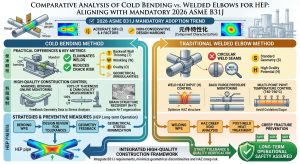
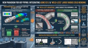
在 2026 版 ASME B31J 規範強制適用的技術變革下,針對高能管線路徑改變處,業界正面臨著傳統「1.5D 預製電銲彎頭(Welded Elbows)」與「3D/5D 大曲率數控冷作彎管(Cold-Formed Bends)」之間的典範轉移43。本章節將針對這兩種工法,從不同利害關係人之實務決策角度進行深度剖析。 Under the technological transformation brought by the mandatory application of the 2026 ASME B31J code, the industry is facing a paradigm shift at locations where high-energy piping changes direction, transitioning between traditional “1.5D prefabricated Welded Elbows” and “3D/5D large-curvature CNC Cold-Formed Bends”43. This section will conduct an in-depth analysis of these two methods from the practical decision-making perspectives of various stakeholders.
9.1 業主視角:管線銲道與冷作彎管維護管理及營運決策 / 9.1 Owner’s Perspective: Maintenance Management and Operational Decisions for Welds vs. Cold Bends
對於發電廠或高階製程設施的業主而言,工廠營運的最大考量在於全生命週期成本(Lifecycle Cost)與高稼動率。For owners of power plants or high-end process facilities, the paramount considerations in plant operations are Lifecycle Cost and high availability.
- 消除第四型 (Type IV) 潛變破裂風險:傳統1.5D 預製電銲彎頭在轉彎最高應力區必須存在環向銲縫,這正是最容易因熱循環誘發第四型潛變疲勞破裂的死穴。業主若導入 3D 或 5D 無縫冷作彎管,等於在幾何結構上徹底拔除了這個風險源43。 Eliminating the risk of Type IV creep cracking: Traditional 1.5D prefabricated welded elbows inevitably possess a circumferential weld in the highest stress zone of the turn, representing the exact Achilles’ heel most susceptible to Type IV creep-fatigue cracking induced by thermal cycling. If owners introduce 3D or 5D seamless cold bends, they effectively eradicate this risk source completely at the geometric structural level43.
- 減少非破壞檢測 (NDE) 與維護成本:每減少一個銲接彎頭,就意味著在建廠階段與未來的歲修排程中,省下兩道高階非破壞檢測(如 PAUT 或 RT)的費用。由於管線銲口減少,未來的維護計畫可以更為精簡,顯著提升了營運與維護管理的決策彈性。
Reducing Non-Destructive Examination (NDE) and maintenance costs: Every welded elbow eliminated equates to saving the cost of two high-tier NDE procedures (such as PAUT or RT) during the plant construction phase and future turnaround schedules. With fewer pipe welds, future maintenance plans can be more streamlined, significantly enhancing decision-making flexibility in operations and maintenance management.
9.2 EPC 承包商設計單位視角:空間佈置與實務考量 / 9.2 EPC Contractor Design Perspective: Spatial Layout and Practical Considerations
對統包商(EPC)的管線應力設計工程師來說,導入 ASME B31J 提供了強大的量化分析依據。For piping stress design engineers at EPC (Engineering, Procurement, and Construction) contractors, the introduction of ASME B31J provides a powerful basis for quantitative analysis.
- 柔性因子 (K) 與 SIF 的優化:依據 ASME B31J 演算法,3D/5D 冷作彎管的應力強度因子(SIF)極度趨近於1.0,相較於傳統 1.5D 彎頭可降低 37% 以上的局部應力放大效應,並且具備更優異的天然柔性45。 Optimization of Flexibility Factor (K) and SIF: According to ASME B31J algorithms, the SIF of 3D/5D cold bends is extremely close to 1.0. Compared to traditional 1.5D elbows, it can reduce the local stress amplification effect by more than 37%, while possessing superior natural flexibility45.
- 資本支出 (CAPEX) 與廠房空間優化:1.5D 彎頭因為缺乏足夠的柔性,過去迫使設計單位必須在管線佈局中加入佔地龐大的 U型膨脹環(Expansion Loops)來吸收熱膨脹。而採用 3D/5D 彎管後,其自身的天然大曲率已足夠消散熱應力,大幅減少了膨脹環的設置,不僅降低了資本支出,更釋放了極具價值的廠房空間43。 Capital Expenditure (CAPEX) and plant space optimization: Because 1.5D elbows lack sufficient flexibility, design units were historically forced to incorporate space-consuming U-shaped Expansion Loops in the piping layout to absorb thermal expansion. By adopting 3D/5D bends, their inherent large curvature is sufficient to dissipate thermal stress, drastically reducing the need for expansion loops. This not only lowers CAPEX but also frees up highly valuable plant floor space43.
9.3 廠務管理者視角:管線銲道與冷作彎管要求 / 9.3 Plant Manager’s Perspective: Requirements for Pipe Welds and Cold Bends
在廠務管理的日常運營中,管線內部的流體動力學與壓降是影響機組效率的關鍵。In the daily operations of plant management, internal piping fluid dynamics and pressure drops are key factors affecting generating unit efficiency.
- 降低流體加速腐蝕 (FAC):當高溫高壓蒸汽流經1.5D 彎頭時,急劇的轉向會在外弧側(Extrados)引發強烈的亂流與流體加速腐蝕(FAC),加速管壁減薄。而 5D 冷作彎管憑藉平緩的幾何過渡,大幅降低了流場紊流度與次級流(Secondary Flow)的沖刷效應,延長了管件壽命43。 Reducing Flow-Accelerated Corrosion (FAC): When high-temperature, high-pressure steam flows through a 1.5D elbow, the sharp turn induces intense turbulence and Flow-Accelerated Corrosion (FAC) on the extrados, accelerating wall thinning. In contrast, a 5D cold bend, aided by its smooth geometric transition, substantially reduces flow field turbulence and the erosive effects of Secondary Flow, extending the lifespan of the fitting43.
- 壓降優化:平緩的 3D/5D 彎曲路徑有助於維持穩定的層流,顯著降低了系統流體壓降,提升了整體發電機組或幫浦的輸送效率48。 Pressure drop optimization: The smooth 3D/5D bending path helps maintain stable laminar flow, significantly reducing system fluid pressure drops and enhancing the overall transport efficiency of generating units or pumps48.
9.4 冷作彎管施作協力廠商視角:管線要求及因應策略 / 9.4 Subcontractor’s Perspective on Cold Bending: Piping Requirements and Response Strategies
站在專業冷作彎管製造商的立場,面對 B31.1 與 B31.3 嚴苛的幾何與應變控制,需要高度精密的生產策略。From the standpoint of professional cold bend manufacturers, facing the stringent geometric and strain controls of B31.1 and B31.3 requires highly precise production strategies.
- 極限纖維伸長率 (EFE) 的控制:傳統1.5D 彎頭的理論彎曲應變極大(ϵ ≈ 33.3%),而 5D 彎管的應變則可大幅降至 10.0%48。協力廠商必須導入數控彎管技術(CNC Cold Bending),精準控制推力與彎矩,防止外弧側減薄與內弧側起皺。 Control of Extreme Fiber Elongation (EFE): The theoretical bending strain of traditional 1.5D elbows is enormous (ϵ ≈ 33.3%), whereas the strain in a 5D bend can be drastically reduced to 10.0%48. Subcontractors must introduce CNC Cold Bending technology to precisely control thrust and bending moments, preventing extrados thinning and intrados wrinkling.
- 尺寸與公差合規因應:協力廠商必須使用先進的內部通蕊軸(Mandrel)與模具設計,方能在極端公差範圍內維持管線真圓度(橢圓度容許極限值常設為≦ 8%)與截面厚度18。 Compliance response for dimensions and tolerances: Subcontractors must utilize advanced internal mandrel and tooling designs to maintain pipe out-of-roundness (ovality limits often set to ≦ 8%) and cross-sectional thickness within extreme tolerance ranges18.
9.5 業界前沿技術「能彎不銲」之三合一工法管理核心價值優化 / 9.5 Value Optimization of the Cutting-Edge “Bend-Instead-of-Weld” 3-in-1 Method
面對 2026 版規範的挑戰與實務痛點,諸如潁璋工程(Yingzhang Engineering)等業界前沿技術發展出了「能彎則彎,不得不銲」的策略思維51。 Facing the challenges and practical pain points of the 2026 code, cutting-edge industry technologies, such as those pioneered by Yingzhang Engineering, have developed the strategic philosophy of “Bend where possible, weld only when necessary“51.
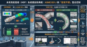
- 三合一工法管理核心:這類前瞻性工程公司成功將「數控冷彎 (CNC Cold Bending)」、「感應加熱管線彎後熱處理 (IH-PBHT)」以及「ASME B31J 高精度力學分析」三者進行了深度的工法整合,構建了所謂的三合一工法43。 Management core of the 3-in-1 method: Such forward-looking engineering companies have successfully integrated three elements—”CNC Cold Bending”, “Induction Heating Post-Bend Heat Treatment (IH-PBHT)”, and “ASME B31J High-Precision Mechanical Analysis”—into a profound method consolidation, constructing the so-called 3-in-1 method43.
- 核心價值優化:這套管理核心將高度依賴師傅經驗的傳統彎管作業,昇華為受嚴格數據化控制的精密成型工法。從設計端源頭即開始優化管口負載,以精準的熱力學控制取代會破壞母材結構的銲接,成為高能管線在結構完整性與專案風險控制上的長期策略夥伴43。 Core value optimization: This management core elevates traditional bending operations—highly dependent on a master’s experience—into a precision forming method under strict data-driven control. Starting straight from the design source to optimize nozzle loads, it replaces welding (which degrades base metal structure) with precise thermodynamic control, acting as a long-term strategic partner for high-energy piping in structural integrity and project risk control43.
9.6 落實以冷作彎管來導入設計(能彎不銲)之核心理念執行與三合一工法之合規 / 9.6 Implementing the “Bend-Instead-of-Weld” Design Philosophy and Compliance of the 3-in-1 Method
要落實「能彎不銲」的理念並確保其完全合規,必須嚴格依循 ASME 的指令性與性能導向要求。To implement the “bend-instead-of-weld” philosophy and ensure its absolute compliance, one must strictly follow the prescriptive and performance-oriented requirements of ASME.
- 彎後熱處理 (PBHT) 的合規落實:針對極限纖維伸長率(EFE)的管理,當應變率大於 5% 但控制在 20% 以下時,三合一工法會強制導入 IH-PBHT(彎後熱處理)。這完全符合 ASME B31.1 對於特定厚度以上材料強制熱處理的保守規定,同時也滿足了 ASME B31.3 中基於伸長率極限值的性能條件18。 Compliant implementation of Post-Bend Heat Treatment (PBHT): Regarding the management of Extreme Fiber Elongation (EFE), when the strain rate exceeds 5% but is controlled below 20%, the 3-in-1 method mandatorily introduces IH-PBHT. This fully complies with the conservative mandate of ASME B31.1 for required heat treatment of materials above a certain thickness, while simultaneously satisfying the performance conditions of ASME B31.3 based on elongation limits18.
- 數位孿生與規範驗證:在執行層面上,該工法不僅將1.5D 的銲縫化為無形,更透過與 ASME B31J 應力解析模型的無縫對接,為 EPC 統包商提供一份「無不合格法規點」的應力計算報告。這確保了在最嚴苛的檢驗環境下,材料的冶金屬性與系統的柔性指標均能超越現行法規的極限值標準,將冷作彎管技術的潛在價值最大化44。 Digital twin and code verification: At the execution level, this method not only renders the 1.5D weld invisible but also—through seamless interfacing with ASME B31J stress analytical models—provides EPC contractors with a stress calculation report featuring “zero non-compliant code points.” This ensures that under the most stringent inspection environments, the metallurgical properties of the material and the flexibility indices of the system can surpass current code limit standards, maximizing the potential value of cold bending technology44.
十、 高壓蒸汽管線洩水坡度 (1°~3°) 設計與凝結水誘發水錘 (CIWH) 防護:1.5D 銲接彎頭與冷作彎管之實務差異 / 10. High-Pressure Steam Piping Drainage Slope (1°~3°) Design and CIWH Protection: Practical Differences Between 1.5D Welded Elbows and Cold Bends
在發電廠與化工業的蒸汽輸送系統中,為防止停機與運轉過程中冷凝水(Condensate)積聚而造成的破壞,管線的幾何佈局必須具備嚴格的洩水坡度。然而,在實務施工中,為了迎合這 1° 到 3° 的微小坡度,採用傳統「1.5D 電銲彎頭」抑或「數控冷作彎管」,將直接決定管線是否會面臨致命的「凝結水誘發水錘」(CIWH)與銲道角錯邊的雙重威脅。In steam transport systems of power plants and the chemical industry, to prevent damage caused by the accumulation of condensate during shutdowns and operations, the geometric layout of piping must feature a strict drainage slope. However, in practical construction, whether to adopt traditional “1.5D welded elbows” or “CNC cold bends” to accommodate this minute 1° to 3° slope directly determines whether the piping will face the dual threats of a fatal “Condensation-Induced Water Hammer” (CIWH) and weld angular misalignment.
10.1 洩水坡度之法規要求與凝結水誘發水錘 (CIWH) 的致命威脅 / 10.1 Regulatory Requirements for Drainage Slopes and the Fatal Threat of Condensation-Induced Water Hammer (CIWH)
依據 ASME B31.1(動力管線規範)與相關工業實踐準則,主蒸汽與凝結水管線必須設置適當的洩水坡度(通常要求為 1:100 至 1:40,約等同於 0.5° 至 1.5°,特定排水條件下甚至要求達 2% 或將近 3° 的傾角),以利凝結水順利靠重力流向卻水器(Steam Trap)或排水低點56。若洩水坡度設計不良或施工精度不足,導致管線內出現積水死角,將誘發極度危險的凝結水誘發水錘(Condensation-Induced Water Hammer, CIWH)現象59。 According to ASME B31.1 (Power Piping) and relevant industrial practice guidelines, main steam and condensate piping must be installed with an appropriate drainage slope (typically required to be 1:100 to 1:40, roughly equivalent to 0.5° to 1.5°; under specific drainage conditions, an incline of up to 2% or nearly 3° may be required) to facilitate the smooth gravity flow of condensate toward steam traps or low drain points56. If the drainage slope is poorly designed or lacks construction precision, resulting in dead legs of pooled water inside the pipe, it will trigger the extremely dangerous phenomenon of Condensation-Induced Water Hammer (CIWH)59.
CIWH 的物理機制與一般流體動能截斷造成的水錘(如快速關閉閥門)不同:當次冷凝結水(Sub-cooled Condensate)積聚於管段死角,而高溫高壓蒸汽通過時,蒸汽會被瞬間冷卻而劇烈凝結。由於蒸汽轉化為液態時體積會急遽縮小,該區域將瞬間形成極低壓的真空穴(Vapor Pocket)。兩側的水柱會在強大壓差驅動下,以極高速度向真空中心撞擊並引發極具破壞性的震波59。CIWH 所產生的強大動能與水段塞(Water Slug)衝擊,足以輕易撕裂管線支撐系統、破壞閥件,甚至導致 P9x 高能管線的接頭發生災難性爆裂61。 The physical mechanism of CIWH differs from ordinary water hammer caused by the abrupt interruption of fluid kinetic energy (such as rapid valve closure): when sub-cooled condensate accumulates in a pipe dead leg and high-temperature, high-pressure steam passes through, the steam is instantly cooled and violently condenses. Because steam shrinks drastically in volume when transitioning to a liquid phase, an extremely low-pressure vapor pocket forms instantaneously in that area. Driven by the massive pressure differential, columns of water on both sides rush toward the vacuum center at extremely high speeds, colliding and triggering highly destructive shockwaves59. The immense kinetic energy and water slug impacts generated by CIWH are enough to easily tear apart piping support systems, destroy valves, and even cause catastrophic bursts at the joints of P9x high-energy piping61.
10.2 1.5D 電銲彎頭在坡度佈建上的實務死角與角錯邊 (Angular Misalignment) 缺陷 / 10.2 Practical Blind Spots and Angular Misalignment Defects of 1.5D Welded Elbows in Slope Layouts
為了在現場管路中創造這 1° 至 3° 的洩水坡度,使用傳統的 1.5D 電銲彎頭(標準出廠角度通常為絕對的 45° 或 90°)會遭遇嚴峻的幾何匹配問題。因為彎頭角度是固定的,施工人員在組對時,往往會面臨兩種高風險的妥協方案:To create this 1° to 3° drainage slope in field piping, using traditional 1.5D welded elbows (which typically have standard factory angles of an absolute 45° or 90°) encounters severe geometric matching problems. Because the elbow angle is fixed, construction personnel during fit-up often face two high-risk compromise scenarios:
- 強行引入角錯邊(Angular Misalignment):為了使水平直管產生 1° 到 3° 的斜角,銲工會在對接 90° 彎頭時強行微調角度。這種組對方式會導致坡口根部一側間隙極小,另一側間隙過大62。這在幾何上無可避免地會引發前述的未銲透(Incomplete Penetration)與內突銲道(Excess Penetration)缺陷。此外,強行組對鎖入的殘餘應力加上不平整的內部銲縫,會使該處的應力集中極限值暴增。 Forcibly introducing Angular Misalignment: To impart a 1° to 3° slant to a horizontal straight pipe, welders will forcibly tweak the angle when butting up against a 90° elbow. This fit-up method results in a bevel root gap that is extremely small on one side and excessively large on the other62. Geometrically, this inevitably triggers the aforementioned Incomplete Penetration and Excess Penetration defects. Furthermore, the residual stress locked in by forced fit-up, combined with the uneven internal weld, causes the stress concentration limit value at that location to skyrocket.
- 實施斜切與斜接管口(Miter Cuts):部分施工單位試圖透過微小的斜切來補償角度。然而,依據 ASME B31.1 (104.3.3) 規範,對於承受高溫、高壓且具備可壓縮性(Compressible)的蒸汽流體,斜接彎頭(Miter Bends)是被極度嚴格限制甚至禁止使用的,因為其幾何突變處會引發難以計算的應力集中與疲勞損傷63。 Executing Miter Cuts: Some construction units attempt to compensate for the angle through minute miter cuts. However, according to the ASME B31.1 (104.3.3) code, for steam fluids that withstand high temperatures, high pressures, and are compressible, Miter Bends are extremely strictly restricted or even prohibited, as the abrupt geometric changes induce incalculable stress concentrations and fatigue damage63.
更嚴重的是,若因這 1° 到 3° 的角錯邊而在彎頭底側形成微小的「反向斜坡」(Adverse Slope),該處將成為完美的「積水死角」。當管線在起停機階段,冷凝水將無法順利排空,直接為 CIWH 提供了溫床65。 Even more seriously, if a minute “Adverse Slope” forms at the bottom side of the elbow due to this 1° to 3° angular misalignment, that spot becomes a perfect “pooling dead leg”. During the startup and shutdown phases of the piping, condensate will be unable to drain smoothly, directly providing a breeding ground for CIWH65.
10.3 3D/5D 數控冷作彎管 (CNC Cold Bend) 應對坡度設計的絕對優勢 / 10.3 Absolute Advantages of 3D/5D CNC Cold Bends in Slope Design
面對嚴苛的 1° 到 3° 洩水坡度要求,採用「能彎不銲」的大曲率數控冷作彎管(3D/5D Cold Bends)展現了決定性的工程優勢:Faced with stringent 1° to 3° drainage slope requirements, adopting large-curvature CNC cold bends (3D/5D Cold Bends) under the “bend-instead-of-weld” philosophy presents decisive engineering advantages:
- 客製化精準角度,實現零角錯邊:數控冷作彎管技術(CNC Cold Bending)不受限於標準的 45° 或 90°。工程師可直接在車間內,精確地將鋼管彎折成 87°、5° 或 92°,以完美吸收並匹配設計圖紙上的 1° 至 3° 洩水坡度66。這意味著管端與後續直管的對接是100%同軸平齊的,徹底消除了現場為了湊角度而產生的「角錯邊」,從根本上確保了銲道根部的熔合品質,避免了內突銲道的產生。 Customized precise angles to achieve zero angular misalignment: CNC Cold Bending technology is not restricted to standard 45° or 90° angles. Engineers can precisely bend steel pipes to 87°, 88.5°, or 92° directly in the workshop to perfectly absorb and match the 1° to 3° drainage slope on the design blueprints66. This means the abutment of the pipe end with the subsequent straight pipe is 100% coaxial and flush, completely eliminating the “angular misalignment” generated on-site while trying to match angles. This fundamentally ensures the fusion quality of the weld root and avoids the formation of excess root penetration.
- 平滑過渡,消滅積水死角與 CIWH 威脅:由於冷作彎管是一體成型且具備平滑漸變的大曲率半徑,管內不存在因銲縫或斜切造成的突兀台階。這保證了冷凝水能夠在 1° 到 3° 的連續坡度下,順暢無阻地滑落至卻水器。消滅了局部的積水死角,即等同於從物理機制上徹底拔除了「凝結水誘發水錘(CIWH)」發生的可能性50。 Smooth transitions to eliminate pooling dead legs and CIWH threats: Because cold bends are integrally formed and possess a smooth, gradually transitioning large radius of curvature, there are no abrupt steps inside the pipe caused by welds or miter cuts. This guarantees that condensate can slide smoothly and unhindered down to the steam trap under a continuous slope of 1° to 3°. Eliminating localized pooling dead legs equates to thoroughly eradicating the possibility of “Condensation-Induced Water Hammer (CIWH)” occurring from a physical mechanics perspective50.
因此,在高壓蒸汽管線的坡度佈建實務中,以冷作彎管取代 1.5D 銲接彎頭,不僅是解決現場組對困難與銲道缺陷的工法優化,更是防範破壞性水錘、延長管線生命週期、確保系統安全的極限值管理策略。Therefore, in the practical slope layout of high-pressure steam piping, replacing 1.5D welded elbows with cold bends is not merely a method optimization to solve on-site fit-up difficulties and weld defects; it is a limit-value management strategy to prevent destructive water hammers, extend the piping lifecycle, and ensure system safety.
十一、 結論 / 11. Conclusion
P9x高能管線在當今追求極致熱效率的超臨界與超超臨界發電廠中,扮演著承受極端溫度與壓力考驗的核心動脈角色。本深度研究報告之分析明確顯示,內外錯邊與內突銲道(銲根下垂)絕對不應被視為單純的視覺幾何瑕疵;它們實則牽動了流體動力學的高速擾動、理論應力集中係數(Kt)的劇烈放大,以及極端致命的高溫潛變-疲勞交互作用(CFI),是加速微裂紋萌生與導致管線災難性破裂的核心觸發機制。P9x high-energy piping plays the role of a core artery enduring extreme temperature and pressure trials in today’s supercritical and ultra-supercritical power plants that pursue ultimate thermal efficiency. The analysis in this in-depth research report clearly indicates that internal/external misalignment and excess root penetration (root sag) must absolutely not be viewed merely as visual geometric flaws; in reality, they drive high-speed disturbances in fluid dynamics, drastic amplifications of the theoretical stress concentration factor (Kt), and the extremely fatal high-temperature Creep-Fatigue Interaction (CFI). They are the core triggering mechanisms that accelerate micro-crack initiation and lead to catastrophic pipeline ruptures.
基於P9x材料高度依賴析出強化與回火麻田散體相變來獲取高溫潛變抗力的本質,其對氫致冷裂(HACC)與幾何缺口的敏感度遠超傳統鋼材。由錯邊與下垂所引入的局部偏心彎矩與三軸拉伸應力,會將破壞性能量無情地集中於銲接接頭最脆弱的臨界間熱影響區(ICHAZ),誘發無巨觀變形預警的第四型潛變破壞;而過度下垂的內突銲道不僅縮減了有效流通截面積,更會因流體的猛烈沖刷腐蝕而急遽加速管壁的劣化與減薄。Based on the inherent nature of P9x materials, which heavily rely on precipitation strengthening and tempered martensitic phase transformations to acquire high-temperature creep resistance, their sensitivity to Hydrogen-Assisted Cold Cracking (HACC) and geometric notches far exceeds that of traditional steels. The localized eccentric bending moments and triaxial tensile stresses introduced by misalignment and sag mercilessly concentrate destructive energy into the weakest Intercritical Heat-Affected Zone (ICHAZ) of the welded joint, inducing Type IV creep failure without any macroscopic deformation warning. Furthermore, excessively sagging internal protrusions not only reduce the effective cross-sectional flow area but also precipitously accelerate wall degradation and thinning due to fierce fluid erosive corrosion.
在國際驗收標準的工程哲學中,無論是遵循高度保守、將尺寸限制視為絕對紅線的ASME B31.1,還是基於性能導向、對嚴重循環疲勞工況採取「零容忍」嚴厲態度的ASME B31.3,抑或是以精密幾何比例公式動態設限的ISO 5817 (Level B),其底層的核心精神皆高度一致:必須窮盡一切工程手段,將局部的應力集中係數控制在材料的彈性與潛變安全包絡線之內。In the engineering philosophies of international acceptance standards—whether adhering to the highly conservative ASME B31.1 which treats dimensional limits as absolute red lines, or the performance-oriented ASME B31.3 which adopts a strict “zero tolerance” attitude towards severe cyclic fatigue conditions, or ISO 5817 (Level B) which dynamically sets limits using precise geometric proportion formulas—their underlying core spirits are highly consistent: all possible engineering measures must be exhausted to control the local stress concentration factors within the material’s elastic and creep safety envelopes.
在未來的工廠製造與現場管理上,除了傳統的精密裝配與熱輸入控制外,導入 ASME B31J 以及「能彎不銲」的大曲率冷作彎管工法,無疑將成為業界的新典範。特別是在滿足嚴格的洩水坡度以防範凝結水誘發水錘(CIWH)時,冷作彎管精準的客製化角度與平滑流道,能徹底免除 1.5D 彎頭帶來的角錯邊與積水死角風險。唯有徹底摒棄僥倖心態,透過嚴格的數位化設計、精準的應變與熱處理控制,並根絕不必要的銲接幾何缺陷,方能確保 P9x 高能管線在長達數十萬小時的極端服役週期內,完美展現其應有的結構完整性與不妥協的安全可靠度。In future shop manufacturing and on-site management, alongside traditional precision fit-up and heat input controls, the introduction of ASME B31J and the “bend-instead-of-weld” large-curvature cold bending method will undoubtedly become a new paradigm in the industry. Particularly when satisfying strict drainage slopes to prevent Condensation-Induced Water Hammer (CIWH), the precisely customized angles and smooth flow channels of cold bends completely eliminate the risks of angular misalignment and pooling dead legs brought about by 1.5D elbows. Only by thoroughly discarding a leave-to-chance mentality—through rigorous digital design, precise strain and heat treatment control, and the eradication of unnecessary welding geometric defects—can it be ensured that P9x high-energy piping will perfectly exhibit its deserved structural integrity and uncompromising safety and reliability over an extreme service lifecycle spanning hundreds of thousands of hours.
參考文獻 / References
- Welding P91 Steel: Essential Requirements – WeldFabWorld, https://www.weldfabworld.com/p91-material-requirement/
- A Study of the Creep-Fatigue Damage Mechanism of a P92 Welded, https://www.mdpi.com/2075-4701/15/1/53
- Significant reduction in creep life of P91 steam pipe elbow caused, https://pmc.ncbi.nlm.nih.gov/articles/PMC10909855/
- Stress concentration factor in plates with transverse butt-weld, http://www.zgkjcx.com/Article/UploadFiles/201101/20110110154734408.pdf
- Stress Concentration Factors Due to Misalignment at Girth Welds in, https://www.mdpi.com/2077-1312/12/2/231
- Creep-Fatigue Life Property Of P91 Welded Piping Subjected To, https://tlooto.com/paper/150261699875
- WELDING SOLUTIONS FOR GRADE 91, https://cdnstorevoestalpine.blob.core.windows.net/image-container/812658/original/BW_Grade_91_EN_2021_GL_135_Preview.pdf
- Hydrogen diffusion in creep-resistant 9% Cr P91 multi-layer weld, https://mediatum.ub.tum.de/doc/1536986/document.pdf
- Assessment of Metallurgy & Welding Procedures of P91 Piping, https://www.odonnellconsulting.com/projects/welding-procedures-p91-pipe/
- Hydrogen induced cold cracking of creep resistant ferritic P91 steel, https://www.semanticscholar.org/paper/Hydrogen-induced-cold-cracking-of-creep-resistant-Pandey-Saini/9bbc0b4c413b72f642443a631b654e3a4756a7bc
- (PDF) Hydrogen effect on mechanical properties and cracking of, https://www.researchgate.net/publication/365600781_Hydrogen_effect_on_mechanical_properties_and_cracking_of_creep-resistant_9_Cr_P92_steel_and_P91_weld_metal
- Mechanical Properties of P91 Steel (X10CrMoVNb9-1) during … – PMC, https://pmc.ncbi.nlm.nih.gov/articles/PMC11396704/
- Purging While Welding | PDF | Corrosion – Scribd, https://www.scribd.com/document/187830539/Purging-While-Welding
- Hydrogen Cracking in Welds — Causes & Prevention | WeldFabWorld, https://www.weldfabworld.com/hydrogen-cracking-welds-causes-prevention-best-practices/
- WELDING ROOT BEAD IN P91 WITH SMAW – Tip Tig USA, https://tiptigusa.com/wp-content/uploads/2020/11/ACHIVEVING-TOUGHNESS-IN-P91-WELDS-FROM-ROOT-TO-CAP-USING-A-HIGH-DEPOSITION-METAL-TRANSFER-HDMT-GTAW-PROCES38464.pdf
- Weld Metals for P91 – Tough Enough?, https://netlite.com.my/wp-content/uploads/2021/10/P91-EPRI-USA-June-2000.pdf
- ASME Permitted Misalignment for Piping, https://qualityinspectionforms.com/weld-codes-standards/asme-permitted-misalignment-for-piping
- ASME B31.1 與ASME B31.3 在冷作彎管要求上差異分析研究(A, https://yz-pipe-bending.com.tw/asme-b31-1-%E8%88%87-asme-b31-3-%E5%9C%A8%E5%86%B7%E4%BD%9C%E5%BD%8E%E7%AE%A1%E8%A6%81%E6%B1%82%E4%B8%8A%E7%9A%84%E5%B7%AE%E7%95%B0%E5%88%86%E6%9E%90%E7%A0%94%E7%A9%B6-a-comparative-analysis-of-cold/
- Stress Concentration, https://s1b0d3d77136c1679.jimcontent.com/download/version/1531108625/module/14143373530/name/Roark-Ch06.pdf
- Creep Properties of P91 Pipe Welds | PDF – Scribd, https://www.scribd.com/document/697411421/1464420041579544
- Creep-Fatigue Life Property of P91 Welded Piping Subjected to, https://www.researchgate.net/publication/372528500_Creep-Fatigue_Life_Property_of_P91_Welded_Piping_Subjected_to_Bending_and_Torsional_Moments_at_High_Temperature
- 2-4: Stress Concentration Caused by Sudden Change in Form – NJIT, https://web.njit.edu/~sengupta/met%20301/Stress%20Concentration.pdf
- Stress Concentration Analysis Explained With Examples – SimuTecra, https://simutecra.com/blogs/stress-concentration-analysis-explained-example
- EXCESSIVE PENETRATION – Welding Inspector, https://berryfitriandi.blogspot.com/2016/10/excessive-penetration.html
- A review of the causes and acceptance of shape imperfections – TWI, https://www.twi-global.com/technical-knowledge/job-knowledge/a-general-review-of-the-causes-and-acceptance-of-shape-imperfections-part-2-068
- Investigation of Weld Root Defects in High-Power Full-Penetration, https://www.mdpi.com/1996-1944/15/3/1095
- Misalignment and Root Gap Standards | PDF – Scribd, https://www.scribd.com/document/358775792/Internal-Misalign
- Analysis of Cracking Causes of P91 Welding Seam of High Pressure, https://www.researchgate.net/publication/349983446_Analysis_of_Cracking_Causes_of_P91_Welding_Seam_of_High_Pressure_Steam_Guide_Pipe_of_Supercritical_Unit
- 1 Interpretations | PDF | Pipe (Fluid Conveyance) | Welding, https://www.scribd.com/document/397910671/b31-1-Interpretations
- ASME B31.3 Acceptance criteria for welds – Eng-Tips, https://www.eng-tips.com/threads/asme-b31-3-acceptance-criteria-for-welds.326321/
- Excess Root Penetration | Eng-Tips, https://www.eng-tips.com/threads/excess-root-penetration.112657/
- Weld defect acceptance/rejection criteria as per ASME B31.1 Power, https://www.weldingandndt.com/weld-defect-acceptance-rejection-criteria-as-per-asme-b31-1-power-piping/
- ASME B31.3 Table 341.3.2 Criteria | PDF | Welding – Scribd, https://www.scribd.com/document/730317414/tabla-y-figura-341-3-2-ASME-B-31-3
- ASME B31.3 Welding Acceptance Criteria | PDF – Scribd, https://www.scribd.com/document/944867417/Acceptance-Criteria-See
- ASME B31.3 B31.1 Pipe Weld Undercut Limits – Rejection Criteria, https://industrialmonitordirect.com/blogs/knowledgebase/asme-b313-and-b311-pipe-weld-undercut-limits-and-rejection-criteria
- ISO 5817: weld quality levels B, C and D – SpawBaza, https://spawacz.waw.pl/en/weld-defects/weld-quality-levels-iso-5817/
- INTERNATIONAL STANDARD ISO 5817, https://uscc.ua/uploads/page/images/normativnye%20dokumenty/dstu/vigotovlennya-mk-mizhnarodna-gilka-standarty/78-dstu-iso-5817-2016-zvaryuvannya.pdf
- What do ISO 5817 quality levels B, C and D mean? – NTB SpecPro, https://ntbspecpro.com/en/iso-5817-quality-levels/
- ISO 5817 Welding Defect Acceptance Levels: B, C, D – AES Innovation, https://aesinn.com/en/test-ve-olcum-hizmetleri/iso-5817-ergitme-kaynakli-baglantilarda-kusur-kabul-seviyeleri-b-c-d-kalite-seviyeleri/
- ISO 5817 Level B vs C vs D: Weld Quality Comparison 2026, https://www.therness.com/blog/iso-5817-level-b-vs-c-vs-d-weld-quality-comparison/
- Weld Joint Preparation According to ASME B31.3 and B31.1, https://gbcspa.com/en/weld-joint-preparation-asme-b31/
- Mastering ASME B31J Piping Stress Analysis for Plant Integrity, https://epcland.com/asme-b31j-piping-stress-analysis/
- 2026版ASME B31J 強制導入下高能管線工程之典範轉移:基於1, https://yz-pipe-bending.com.tw/2026%E7%89%88-asme-b31j-%E5%BC%B7%E5%88%B6%E5%B0%8E%E5%85%A5%E4%B8%8B%E9%AB%98%E8%83%BD%E7%AE%A1%E7%B7%9A%E5%B7%A5%E7%A8%8B%E4%B9%8B%E5%85%B8%E7%AF%84%E8%BD%89%E7%A7%BB%EF%BC%9A%E5%9F%BA%E6%96%BC-b31/
- 基於2025/2026 ASME B31.1 與B31J 最新規範複循環機組動力管線冷, https://yz-pipe-bending.com.tw/%E5%9F%BA%E6%96%BC-2025-2026-asme-b31-1-%E8%88%87-b31j-%E6%9C%80%E6%96%B0%E8%A6%8F%E7%AF%84%E8%A4%87%E5%BE%AA%E7%92%B0%E6%A9%9F%E7%B5%84%E5%8B%95%E5%8A%9B%E7%AE%A1%E7%B7%9A%E5%86%B7%E4%BD%9C%E5%BD%8E/
- 2026 ASME B31J 規範下冷作彎管曲率半徑(R值)選用準則與實務應用, https://yz-pipe-bending.com.tw/%E9%AB%98%E9%BB%8F%E5%BA%A6%E9%9D%9E%E7%89%9B%E9%A0%93%E6%B5%81%E9%AB%94%E7%AE%A1%E7%B7%9A%E8%BC%B8%E9%80%81%E4%B9%8B%E6%B5%81%E5%9B%BA%E8%80%A6%E5%90%88%E8%88%87%E5%8A%9B%E5%AD%B8%E6%9C%80%E4%BD%B3/
- 基於2026 年版ASME B31J 規範之CCPP 高能蒸汽管線冷作彎管工法, https://yz-pipe-bending.com.tw/%E5%9F%BA%E6%96%BC-2026-%E5%B9%B4%E7%89%88-asme-b31j-%E8%A6%8F%E7%AF%84%E4%B9%8B-ccpp-%E9%AB%98%E8%83%BD%E8%92%B8%E6%B1%BD%E7%AE%A1%E7%B7%9A%E5%86%B7%E4%BD%9C%E5%BD%8E%E7%AE%A1%E5%B7%A5%E6%B3%95/
- 基於2026 ASME B31.1/B31.3 (B31J) 之高能管線佈局優化策略:冷作, https://yz-pipe-bending.com.tw/%E5%9F%BA%E6%96%BC-2026-asme-b31-1-b31-3-b31j-%E4%B9%8B%E9%AB%98%E8%83%BD%E7%AE%A1%E7%B7%9A%E4%BD%88%E5%B1%80%E5%84%AA%E5%8C%96%E7%AD%96%E7%95%A5%EF%BC%9A%E5%86%B7%E4%BD%9C%E5%BD%8E%E7%AE%A1/
- 基於2026 ASME B31J 規範之CCPP 高能管線設計最佳化, https://yz-pipe-bending.com.tw/%E5%9F%BA%E6%96%BC-2026-asme-b31j-%E8%A6%8F%E7%AF%84%E4%B9%8B-ccpp-%E9%AB%98%E8%83%BD%E7%AE%A1%E7%B7%9A%E8%A8%AD%E8%A8%88%E6%9C%80%E4%BD%B3%E5%8C%96%EF%BC%9Aa106-%E7%A2%B3%E9%8B%BC%E5%A4%A7%E5%8D%8A/
- Pipe Stress & Flexibility Calculator, https://designcalculators.co.in/pipe-stress-flexibility
- Elbow vs Bend: Key Differences Explained | Pipe (Fluid Conveyance), https://www.scribd.com/document/456651232/Difference-between-pipe-and-elbow
- 潁璋工程興業有限公司– 冷作彎管, https://yz-pipe-bending.com.tw/
- 專案管線工程中「銲接與冷作彎曲混合式工法」之技術, https://yz-pipe-bending.com.tw/%E7%AE%A1%E7%B7%9A%E5%B7%A5%E7%A8%8B%E4%B8%AD%E3%80%8C%E9%8A%B2%E6%8E%A5%E8%88%87%E5%86%B7%E4%BD%9C%E5%BD%8E%E6%9B%B2%E6%B7%B7%E5%90%88%E5%BC%8F%E5%B7%A5%E6%B3%95%E3%80%8D%E4%B9%8B%E6%8A%80%E8%A1%93/
- ASME B31.1 規範中”設計者”定義之引入對大型EPC 專案技術核可與, https://yz-pipe-bending.com.tw/asme-b31-1-%E8%A6%8F%E7%AF%84%E4%B8%AD%E8%A8%AD%E8%A8%88%E8%80%85%E5%AE%9A%E7%BE%A9%E4%B9%8B%E5%BC%95%E5%85%A5%E5%B0%8D%E5%A4%A7%E5%9E%8B-epc-%E5%B0%88%E6%A1%88%E6%8A%80%E8%A1%93%E6%A0%B8%E5%8F%AF/
- 2026 ASME 規範下1 動力管線施工工法之深度剖析:5D 冷作彎, https://yz-pipe-bending.com.tw/2026-asme-%E8%A6%8F%E7%AF%84%E4%B8%8B-b31-1-%E5%8B%95%E5%8A%9B%E7%AE%A1%E7%B7%9A%E6%96%BD%E5%B7%A5%E5%B7%A5%E6%B3%95%E4%B9%8B%E6%B7%B1%E5%BA%A6%E5%89%96%E6%9E%90%EF%BC%9A5d-%E5%86%B7%E4%BD%9C%E5%BD%8E/
- About – 潁璋工程興業有限公司, https://yz-pipe-bending.com.tw/about/
- Aircon Condensate Drain Pipe Sizing and Slope Standards, https://skyblueaircon.com/blog/condensate-drain-pipe-sizing-slope-standards-drainage-pipe-clearing
- What is Steam Piping? Design Considerations for Steam Piping, https://whatispiping.com/steam-piping/
- Steam Pipe Slope – Eng-Tips, https://www.eng-tips.com/threads/steam-pipe-slope.300860/
- (PDF) How to Prevent Condensation-Induced Water Hammer, https://www.researchgate.net/publication/362318197_How_to_Prevent_Condensation-Induced_Water_Hammer
- (PDF) A comprehensive review on pressurized thermal shock, https://www.researchgate.net/publication/343082045_A_comprehensive_review_on_pressurized_thermal_shock_predictive_preventive_and_safety_issues
- CCPP 高壓蒸汽管線抗動態負荷之最佳化設計:冷作彎管工法與管線, https://yz-pipe-bending.com.tw/ccpp-%E9%AB%98%E5%A3%93%E8%92%B8%E6%B1%BD%E7%AE%A1%E7%B7%9A%E6%8A%97%E5%8B%95%E6%85%8B%E8%B2%A0%E8%8D%B7%E4%B9%8B%E6%9C%80%E4%BD%B3%E5%8C%96%E8%A8%AD%E8%A8%88%EF%BC%9A%E5%86%B7%E4%BD%9C%E5%BD%8E/
- Fall/Winter 2024 by Sulfuric Acid Today – Issuu, https://issuu.com/sulfuricacidtoday/docs/fall_winter_2024
- What is a Miter Bend? Design Formulas for Miter Bend Calculation, https://whatispiping.com/miter-bend-calculation-formula/
- 1 allowable miter in steam pipe | Eng-Tips, https://www.eng-tips.com/threads/b31-1-allowable-miter-in-steam-pipe.222102/
- 複循環電廠高壓蒸汽管線洩水坡度設計與管件工法比較:斜切對銲, https://yz-pipe-bending.com.tw/%E8%A4%87%E5%BE%AA%E7%92%B0%E9%9B%BB%E5%BB%A0%E9%AB%98%E5%A3%93%E8%92%B8%E6%B1%BD%E7%AE%A1%E7%B7%9A%E6%B4%A9%E6%B0%B4%E5%9D%A1%E5%BA%A6%E8%A8%AD%E8%A8%88%E8%88%87%E7%AE%A1%E4%BB%B6%E5%B7%A5%E6%B3%95/
- How To Bend Pipes For Pipeline? – YouTube, https://www.youtube.com/watch?v=EFI4zrc_GNo
- JSW Pipeline Cold Bending Services, https://www.pipetechservice.com/pipeline-cold-bending/