
摘要 / Abstract
高能管線(High Energy Piping, HEP)系統廣泛應用於火力發電、汽電共生、先進燃氣複循環發電廠(CCPP)以及各類具備高溫高壓蒸汽流體之重工業設施中。其主要特徵為在極端溫度與壓力環境下傳輸過熱蒸汽或鍋爐給水。這類管線若發生破裂或材料失效,將釋放極大的熱能與動能,導致毀滅性的工安事故與難以估量的經濟損失。因此,高能管線的設計、製造、傳統配管裝配、銲接、非破壞性檢驗(NDE)以及試車前的調試,均須遵循極為嚴格的工程規範與標準作業程序(SOP)1。High Energy Piping (HEP) systems are widely utilized in thermal power generation, cogeneration, advanced combined-cycle power plants (CCPP), and various heavy industrial facilities involving high-temperature and high-pressure steam fluids. Their primary characteristic is the transport of superheated steam or boiler feedwater under extreme temperature and pressure environments. If such piping ruptures or experiences material failure, it releases immense thermal and kinetic energy, leading to catastrophic industrial accidents and incalculable economic losses. Therefore, the design, manufacturing, traditional piping fit-up, welding, non-destructive examination (NDE), and pre-commissioning procedures for high energy piping must strictly adhere to rigorous engineering codes and standard operating procedures (SOP)1.
在國際主流工程與學術實務中,美國機械工程師學會(ASME)所頒布之 B31.1《動力管線規範》(Power Piping Code)與 ASME 鍋爐及壓力容器法規(BPVC)構成了高能管線建置與生命週期完整性評估的核心法規框架1。本研究旨在透過嚴謹的學術分析視角,針對傳統配管工法於高能管線建置過程中的標準作業程序進行深度解構,並進一步對比先進冷作彎管工法。分析範疇涵蓋管壁厚度之應力力學模型、銲接程序檢定體系、裝配幾何寬容度、高階耐熱鋼之潛變機制與銲後熱處理(PWHT)、非破壞性檢驗斷裂力學,以及蒸汽吹管(Steam Blowing)流體力學。透過探討各工程環節間的基礎物理機制,本報告提供了一套具備高度技術洞察之高能管線系統生命週期安全建構架構。In mainstream international engineering and academic practice, the ASME B31.1 Power Piping Code and the ASME Boiler and Pressure Vessel Code (BPVC) form the core regulatory framework for the construction and lifecycle integrity assessment of HEP1. This study aims to deeply deconstruct the standard operating procedures of traditional piping fabrication in HEP construction through a rigorous academic analytical perspective, while further comparing them with advanced cold bending methods. The scope of analysis covers stress mechanics models for wall thickness, welding procedure qualification systems, geometric fit-up tolerances, creep mechanisms and post-weld heat treatment (PWHT) in advanced heat-resistant steels, NDE fracture mechanics, and the fluid dynamics of steam blowing. By exploring the fundamental physical mechanisms bridging these engineering phases, this report provides a highly insightful technical framework for ensuring the lifecycle safety of high energy piping systems.
一、 法規管轄權界定與管壁厚度設計之應力力學模型 / I. Code Jurisdiction and Stress Mechanics Modeling for Wall Thickness Design
高能管線的法規適用性主要由 ASME B31.1 主導,其設計理念著眼於發電廠需要長達數十年之長週期運轉與極高的熱力學可靠度。在 B31.1 的法規定義中,系統被嚴格區分為「鍋爐外部管線」(Boiler External Piping, BEP)與「非鍋爐外部管線」(Non-Boiler External Piping, NBEP)1。The regulatory applicability of HEP is primarily governed by ASME B31.1, whose design philosophy focuses on the requirement for decades of long-term operation and extremely high thermodynamic reliability in power plants. Under the B31.1 code definitions, the system is strictly categorized into Boiler External Piping (BEP) and Non-Boiler External Piping (NBEP)1.
BEP 指的是連接鍋爐主體至特定閥門(通常為鍋爐外的第一或第二個隔離閥)之間的管線。在法規管轄權上,BEP 受到 ASME Section I (Power Boilers) 的直接管轄,其設計、製造與檢驗必須具備國家委員會(National Board)授權檢驗師(AI)的查驗,並強制打上 ASME “S” 或 “PP” 法定鋼印1。相對而言,NBEP 涵蓋了其他所有發電廠內的動力管線(如部分主蒸汽、再熱蒸汽、給水與冷凝水管線),NBEP 雖不需法定鋼印,但仍須嚴格遵守 B31.1 之所有設計與製造規則1。BEP refers to the piping connecting the boiler proper to specific valves (typically the first or second isolation valve outside the boiler). In terms of code jurisdiction, BEP is directly governed by ASME Section I (Power Boilers); its design, fabrication, and examination must be verified by an Authorized Inspector (AI) commissioned by the National Board and mandatorily stamped with the ASME “S” or “PP” symbol1. In contrast, NBEP covers all other power piping within the plant (e.g., portions of main steam, reheat steam, feedwater, and condensate piping). Although NBEP does not require a statutory stamp, it must still strictly comply with all design and fabrication rules of B31.11.
1.1 ASME B31.1 與 B31.3 之設計哲學比較與適用性 / 1.1 Comparison of Design Philosophies and Applicability Between ASME B31.1 and B31.3
在重工業建廠工程實務中,經常需要辨析 ASME B31.1(動力管線)與 ASME B31.3(製程管線)的適用邊界。B31.1 的設計裕度相對保守,其應力允許值反映了電力設施無法容忍非計畫性停機的特性4。兩者在設計壓力計算、銲後熱處理極限值及非破壞檢驗的判定邏輯上存在本質差異。B31.1 對於同等材質與厚度的檢驗與熱處理要求通常更為嚴苛,且不採用 B31.3 中基於流體服務類別(Fluid Service Category)的分類法7。In heavy industrial plant engineering practice, it is often necessary to distinguish the applicability boundaries between ASME B31.1 (Power Piping) and ASME B31.3 (Process Piping). B31.1 has a relatively conservative design margin, with allowable stress values reflecting the intolerance of power facilities for unplanned outages4. Fundamental differences exist between the two regarding design pressure calculations, post-weld heat treatment thresholds, and evaluation logic for non-destructive examinations. B31.1 typically imposes stricter examination and heat treatment requirements for equivalent materials and thicknesses, and it does not adopt the Fluid Service Category classification method found in B31.37.
| 比較項目 / Comparison Item | ASME B31.1 (動力管線 / Power Piping) | ASME B31.3 (製程管線 / Process Piping) |
| 主要應用領域 / Primary Application Areas | 發電廠、鍋爐外部管線、高溫高壓蒸汽系統 / Power plants, BEP, high-temp/high-pressure steam systems1 | 煉油廠、石化廠、化學製程管線 / Refineries, petrochemical plants, chemical process piping8 |
| 法規管轄權限 / Jurisdictional Authority | BEP 需受 ASME Sec. I 管轄並具備 “S” 或 “PP” 鋼印 / BEP is governed by Sec. I and requires “S” or “PP” stamp1 | 無特定的鍋爐法定鋼印要求 / No specific statutory boiler stamp requirement1 |
| 銲後熱處理 (PWHT) / Post-Weld Heat Treatment | 針對碳鋼材料,較薄壁厚即可能要求 PWHT,極限嚴格 / Strict limits; PWHT may be required for carbon steel even at lower thicknesses8 | PWHT 的厚度豁免極限值相對較高,條件較為彈性 / Higher thickness exemption thresholds for PWHT, more flexible conditions8 |
| 非破壞檢驗 (NDE) / Non-Destructive Exam | 依據銲道類型與溫壓條件決定強制檢驗比例 / Mandatory inspection percentages determined by weld type and pressure/temp conditions1 | 依據流體服務類別決定檢驗比例 / Inspection percentages determined by fluid service categories7 |
1.2 直管受內壓之管壁厚度計算理論 (Paragraph 104.1.2) / 1.2 Theoretical Calculation of Wall Thickness for Straight Pipe Under Internal Pressure (Paragraph 104.1.2)
高能管線的核心力學設計在於抵抗高溫潛變(Creep)與內部高壓所產生的環向應力(Hoop Stress)。根據彈性力學中的薄壁與厚壁圓筒理論,ASME B31.1 段落 104.1.2 提供了直管承受內壓時之壓力設計厚度計算公式12:The core mechanical design of high energy piping lies in resisting high-temperature creep and the hoop stress generated by high internal pressure. Based on thin- and thick-walled cylinder theories in elasticity, ASME B31.1 Paragraph 104.1.2 provides the pressure design thickness calculation formula for straight pipe under internal pressure12:
t=P⋅Do/2(SEW+Py)
公式中各項變數具備深刻的物理與力學意義:The variables in the formula possess profound physical and mechanical significance:
- t:壓力設計厚度,即純粹為抵抗內壓所需之理論最小金屬厚度12。 / Pressure design thickness, the theoretical minimum metal thickness required purely to resist internal pressure12.
- P:內部設計表壓力12。 / Internal design gauge pressure12.
- Do:管線外徑(Outside diameter)。法規選擇外徑而非內徑作為計算基準,是因標準管材規格(NPS)的外徑為固定值,便於標準化設計12。 / Outside diameter of the pipe. The code utilizes the OD because the outside diameter in nominal pipe size (NPS) standards is a fixed value, facilitating standardized design12.
- SE:最大允許應力(S)與縱向銲縫效率(E)之乘積,該數值取自1 附錄 A 之應力表,反映了材料在特定溫度下的降伏強度或潛變破裂強度之安全折減12。 / The product of maximum allowable stress (S) and longitudinal weld joint efficiency (E), taken from B31.1 Appendix A. It reflects the safety reduction of the material’s yield strength or creep rupture strength at a specific temperature12.
- W:銲縫強度折減係數。這是近代法規針對高溫管線引入的重要參數。在溫度低於潛變範圍時,預設為1.0;但進入潛變溫度範圍後,W 值將小於 1.0,以補償銲縫金屬與熱影響區在高溫下的長期潛變破裂強度低於母材之現象12。 / Weld Strength Reduction Factor (WSRF). This is a critical parameter introduced in modern codes for high-temperature piping. It defaults to 1.0 below the creep range; however, upon entering the creep temperature range, the W value becomes less than 1.0 to compensate for the fact that the long-term creep rupture strength of the weld metal and heat-affected zone at high temperatures is lower than that of the base metal12.
- y:溫度係數(Temperature coefficient),取自 Table 104.1.2-1。此係數用以補償管壁在高溫下,應力由內壁向外壁重新分佈(Stress redistribution)的非線性力學效應。對於肥粒鐵鋼材,當溫度低於 482°C 時 y = 0.4;進入潛變範圍後(> 510°C)可高達0.712。 / Temperature coefficient, taken from Table 104.1.2-1. This coefficient compensates for the non-linear mechanical effect of stress redistribution from the inner wall to the outer wall at high temperatures. For ferritic steels, y = 0.4 when the temperature is below 482°C; it can reach up to 0.7 upon entering the creep range (> 510°C)12.
在得出壓力設計厚度 t 後,工程設計尚未完成。必須加上額外的機械餘裕(如螺紋與溝槽深度)、腐蝕餘裕與沖蝕餘裕(統稱為 A),得出最小需求壁厚 tm = t + A 12。更關鍵的是,無縫鋼管在煉鋼廠軋製過程中存在負容許差(Mill Under-tolerance,依據 ASTM 規範通常為 12.5%)。因此,採購規格之標稱厚度(torder)必須進一步以幾何級數放大,即 torder=tm/(1-0.125)12。若工程師忽略此軋製容許差,直接以 tm 進行採購,將導致實際交付之管材在薄端處低於法規設計底限,這在授權檢驗師的審查中屬於致命且必須退件的重大缺失12。After obtaining the pressure design thickness t, the engineering design is not yet complete. Additional mechanical allowances (such as thread and groove depths), corrosion allowances, and erosion allowances (collectively termed A) must be added to derive the minimum required wall thickness tm = t + A 12. More crucially, seamless steel pipes exhibit a negative mill under-tolerance during the steel mill rolling process (typically 12.5% according to ASTM standards). Therefore, the nominal thickness for procurement specifications (torder) must be further scaled up geometrically, meaning torder=tm/(1-0.125)12. If engineers overlook this mill tolerance and procure directly using tm, the actual delivered pipes will fall below the code’s design minimum at the thinner ends, constituting a fatal non-compliance that will result in rejection during the Authorized Inspector’s review12.
從此力學公式可延伸出深度的工程洞察:在極端高溫高壓條件(例如超臨界機組主蒸汽管線 1,500 psi,超過 510°C 的潛變區)下, Py項在分母中不再僅是微小的誤差修正值,其對整體壁厚分母的影響可達 6% 甚至更高12。同時,EPRI(美國電力研究院)指南特別強調了 W 係數的引入,證明了傳統假設「銲縫與母材等強」的觀念在潛變範圍內已完全失效14。Profound engineering insights can be extended from this mechanical formula: Under extreme high-temperature and high-pressure conditions (e.g., supercritical unit main steam piping at 1,500 psi in the creep region above 510°C), the Py term in the denominator is no longer just a minor error correction; its impact on the overall wall thickness denominator can reach 6% or higher12. Simultaneously, guidelines from EPRI (Electric Power Research Institute) specifically emphasize the introduction of the W factor, proving that the traditional assumption of “equal strength between weld and base metal” is entirely invalid within the creep range14.
二、 傳統配管裝配工序與幾何公差控制 / II. Traditional Piping Fit-Up Procedures and Geometric Tolerance Control
在 ASME B31.1 第五章(Chapter V: Fabrication, Assembly, and Erection)中,針對高能管線在現場的傳統配管裝配(Fit-up)、邊緣準備(Edge Preparation)與假銲(Tack Welding)制定了極為嚴格且量化的幾何寬容度。相較於新興的 5D 大曲率半徑冷作彎管工法(Cold Bending),傳統配管工法高度依賴對接銲,因此坡口的加工精度直接決定了銲道的抗疲勞與抗潛變能力20。In ASME B31.1 Chapter V (Fabrication, Assembly, and Erection), extremely strict and quantified geometric tolerances are established for the traditional piping fit-up, edge preparation, and tack welding of high energy piping in the field. Compared to the emerging 5D large-radius cold bending methodology, traditional piping fabrication relies heavily on butt welds; thus, the machining precision of the bevel directly determines the weld’s fatigue and creep resistance20.
2.1 坡口幾何與裝配公差 / 2.1 Bevel Geometry and Fit-Up Tolerances
管線對接銲(Butt Weld)的冶金與幾何品質,在很大程度上取決於初始的裝配對心。B31.1 規定,相鄰管件的內部錯位(Internal Misalignment,工程術語稱 Hi-Lo)最大不得超過 1/16 英吋(約 1.6 mm)22。內部錯位若過大,將在管根部形成應力集中點(Stress Riser),並在高速蒸汽流過時產生強烈的流體擾動,進而誘發熱疲勞裂紋。The metallurgical and geometric quality of pipe butt welds depends largely on initial fit-up alignment. B31.1 stipulates that the maximum internal misalignment (engineering term “Hi-Lo”) between adjacent piping components must not exceed 1/16 inch (approx. 1.6 mm)22. If the internal misalignment is too large, it forms a stress riser at the weld root and creates intense fluid turbulence when high-speed steam flows through, subsequently inducing thermal fatigue cracking.
當連接的兩管件存在壁厚差異,導致內部錯位大於 1/16 英吋時,法規禁止強行拉平,必須透過精密的內孔加工(Boring)或打磨,將過渡區域的斜度控制在最大 30 度(即 3:1 的幾何錐度),以確保應力線的平滑過渡22。此外,B31.1 亦規範,管線彎曲處的扁平度(Flattening)不得超過公稱外徑的 5%,而在銲接端部的扁平度則被嚴格限制在 3% 以內24。When joining two components with differing wall thicknesses resulting in an internal misalignment greater than 1/16 inch, the code prohibits forceful alignment. It mandates precision internal boring or grinding to control the transition slope to a maximum of 30 degrees (i.e., a 3:1 geometric taper) to ensure a smooth transition of stress lines22. Furthermore, B31.1 specifies that flattening at pipe bends must not exceed 5% of the nominal outside diameter, while flattening at the weld ends is strictly limited to within 3%24.
對於承插銲(Socket Weld),由於銲接收縮與管線服役時的熱膨脹會在根部產生極大的剪切應力,法規強制要求管子插入套筒底端後,必須向外拔出(Withdrawn)約 1/16 英吋(1.6 mm)的間隙再進行銲接,以避免熱膨脹頂破承插接頭22。對於 T 型或角銲(Fillet Weld),裝配間隙最大不得超過 3/16 英吋;若間隙大於 1/16 英吋,則角銲的銲腳尺寸(Leg size)必須依據間隙量等比例增加,以補償有效喉深(Throat thickness)的物理損失4。For socket welds, because weld shrinkage and thermal expansion during service generate immense shear stress at the root, the code mandatorily requires the pipe to be withdrawn approximately 1/16 inch (1.6 mm) after bottoming out in the socket prior to welding, in order to prevent thermal expansion from cracking the socket joint22. For T-joints or fillet welds, the fit-up gap must not exceed 3/16 inch; if the gap exceeds 1/16 inch, the fillet weld leg size must be proportionally increased by the amount of the gap to compensate for the physical loss of effective throat thickness4.
2.2 表面清潔與假銲 (Tack Weld) 管控 / 2.2 Surface Cleaning and Tack Weld Control
銲接前的表面清潔是防止冶金缺陷的第一道防線。必須徹底清除坡口表面及兩側至少 1 英吋(通常 WPS 建議 25 mm 以上)範圍內的油污、鐵鏽、氧化皮、油脂與漆料23。其背後的物理化學機制在於,殘留的碳氫化合物在高溫電弧的熱解作用下會釋放出游離態的原子氫。這些微小的氫原子會輕易溶入液態熔池,若未能在金屬凝固降溫前擴散溢出,便會積聚於熱影響區(HAZ)的晶界與差排處,引發極具破壞性的延遲性氫誘發裂紋(Hydrogen-Induced Cracking, HIC),或稱為冷裂紋23。Pre-weld surface cleaning is the first line of defense against metallurgical defects. Oil, rust, mill scale, grease, and paint must be thoroughly removed from the bevel surface and at least 1 inch (usually >25 mm recommended by WPS) on either side23. The underlying physicochemical mechanism is that residual hydrocarbons will release free atomic hydrogen under the pyrolytic action of the high-temperature arc. These minuscule hydrogen atoms easily dissolve into the liquid weld pool; if they fail to diffuse out before the metal solidifies and cools, they will accumulate at grain boundaries and dislocations within the heat-affected zone (HAZ), causing highly destructive delayed hydrogen-induced cracking (HIC), also known as cold cracking23.
假銲(Tack welds)雖然是裝配過程中的臨時固定手段,但法規要求其冶金質量必須與正式銲道等同,且執行假銲的銲工必須具備合格的 ASME Section IX 資格。B31.1 規定,若假銲出現裂紋或嚴重缺陷,必須在正式銲接前徹底刨除或研磨至露出健全金屬22。在使用消耗性嵌件(Consumable inserts)的特殊高階銲接中,銲接於嵌件上的 GTAW 假銲點若出現微裂紋,必須在正式打底銲時重新完全熔合(Re-fused),以徹底消除物理缺陷22。Although tack welds are temporary securing measures during the fit-up process, the code requires their metallurgical quality to be equivalent to the final weld, and the welder performing the tack welds must hold valid ASME Section IX qualifications. B31.1 mandates that if tack welds exhibit cracks or severe defects, they must be entirely chipped or ground down to sound metal prior to final welding22. In specialized high-end welding using consumable inserts, if GTAW tack welds on the inserts display micro-cracks, they must be completely re-fused during the formal root pass to thoroughly eliminate physical defects22.
三、 銲接程序檢定與變數控制體系 (ASME Section IX) / III. Welding Procedure Qualification and Variable Control System (ASME Section IX)
在傳統配管工法中,銲接接頭的品質決定了高能管線的整體生命週期。ASME B31.1 明文強制規定,所有壓力邊界的銲接程序與銲工資格,均須嚴格依照 ASME Section IX(BPVC 第九卷)進行檢定1。然而,工程實務中常見的誤解是將 Section IX 視為單一的驗收標準。事實上,Section IX 僅為「資格檢定標準」(Qualification Standard),其自身並不包含生產銲道的非破壞檢驗驗收標準,也不決定是否需要銲後熱處理;所有的驗收基準皆須回歸至施工法規(即 B31.1)9。In traditional piping fabrication, the quality of the welded joints determines the overall lifecycle of the high energy piping. ASME B31.1 explicitly mandates that all welding procedures and welder qualifications for pressure boundaries must be strictly qualified in accordance with ASME Section IX (BPVC Section IX)1. However, a common misconception in engineering practice is treating Section IX as a standalone acceptance standard. In reality, Section IX is purely a “Qualification Standard”; it inherently contains no non-destructive examination acceptance criteria for production welds, nor does it dictate whether PWHT is required. All acceptance benchmarks must revert to the construction code (i.e., B31.1)9.
3.1 WPS、PQR 與 WPQ 之嚴密鏈結關係 / 3.1 The Strict Linkage among WPS, PQR, and WPQ
ASME Section IX (Part QG & QW) 建立了一套基於物理數據的證明與指導體系,確保銲接冶金的可重複性。其核心文件鏈包含29: ASME Section IX (Part QG & QW) establishes an evidentiary and guidance system based on physical data to ensure the repeatability of welding metallurgy. Its core documentation chain includes29:
- 程序檢定紀錄:此為客觀的實驗數據證據文件,記錄了試片銲接時的「真實量測數值」(如實際使用的電流、電壓、預熱溫度),而非範圍。PQR 必須附上實驗室的拉伸試驗(Tension tests)與彎曲試驗(Bend tests)等破壞性測試結果,證明該程序能達到母材法定的最低拉伸強度與足夠的延展性28。 Procedure Qualification Record (PQR): This is an objective evidentiary document of experimental data, recording the “actual measured values” used during the welding of the test coupon (such as actual current, voltage, preheat temperature), rather than ranges. The PQR must be accompanied by destructive testing results from a laboratory, such as tension tests and bend tests, proving that the procedure can achieve the specified minimum tensile strength and sufficient ductility of the base metal28.
- 銲接程序規範:這是一份提供給現場銲接技師遵循的書面指令,詳列了製程中允許的各項變數範圍29。每一個 WPS 上所列出的參數範圍,都必須有至少一份(或多份)合格的 PQR 在背後作為物理支撐28。 Welding Procedure Specification (WPS): This is a written directive provided for field welders to follow, detailing the permissible ranges of various variables during the manufacturing process29. Every parameter range listed on a WPS must be physically supported by at least one (or more) qualified PQRs28.
- 銲工技能檢定:透過實際銲接試片並進行射線或彎曲測試,證明特定銲工具備足夠的手感穩定度與技術,能執行特定 WPS 並產出無缺陷之健全銲道1。 Welder Performance Qualification (WPQ): Through actual welding of a test coupon and subsequent radiographic or bend testing, this demonstrates that a specific welder possesses sufficient manual stability and skill to execute a specific WPS and produce a sound, defect-free weld1.
3.2 QW-400 變數分類機制與合規監控 / 3.2 QW-400 Variable Classification Mechanism and Compliance Monitoring
在 ASME Section IX 中,決定現有 PQR 是否仍然有效,或是否需要重新銲接試片的核心在於「變數」(Variables)的分類機制。任何偏離現有 WPS 規範的變更,將依據其對銲道機械性質與冶金組織的影響程度,被嚴格劃分為三大類29:In ASME Section IX, determining whether an existing PQR remains valid or whether a new test coupon needs to be welded hinges on the “Variables” classification mechanism. Any deviation from the existing WPS specifications is strictly divided into three major categories based on its degree of impact on the mechanical properties and metallurgical structure of the weld29:
| 變數類別 / Variable Category | 定義與冶金影響 / Definition and Metallurgical Impact | 實務範例 / Practical Examples | 法規處置方式 / Code Disposition |
| 基本變數 (Essential Variables) | 直接影響銲接接頭之機械性質(如抗拉強度、潛變抗力、延展性)。 / Directly affect the mechanical properties of the welded joint (e.g., tensile strength, creep resistance, ductility). | 母材群組 (P-Number) 變更、銲材可用性群組 (F-Number) 改變、取消或增加 PWHT、母材厚度超出 QW-451 合格範圍30。 / Change in P-Number, F-Number, addition/deletion of PWHT, base metal thickness exceeding QW-451 limits30. | 強制要求:必須停止生產,重新施銲試片,並經破壞性測試通過後制定新的 PQR30。 / Mandatory: Stop production, weld a new test coupon, pass destructive testing, and establish a new PQR30. |
| 非基本變數 (Non-essential Variables) | 經驗證實對金屬機械性質無顯著負面影響之施工變數。 / Construction variables empirically proven to have no significant negative impact on metal mechanical properties. | 坡口設計角度微調(如 60° 變為 70°)、背面清根方法改變、表面清潔方法改變30。 / Minor adjustment to bevel angle (e.g., 60° to 70°), change in back gouging method, change in surface cleaning method30. | 無須製作新的 PQR,僅需由工程師以書面形式修訂並升版 WPS 文件即可30。 / No new PQR is required; engineers merely need to formally revise and up-rev the WPS document30. |
| 補充基本變數 (Supplementary Essential Variables) | 僅在施工法規要求進行衝擊試驗(Notch-toughness)時,才會生效並升級為基本變數。 / Become active and upgraded to essential variables only when the construction code requires notch-toughness (impact) testing. | 銲接位置改變、熱輸入量(Heat Input)顯著增加、層間溫度上限提高30。 / Change in welding position, significant increase in Heat Input, raised maximum interpass temperature30. | 視同基本變數處理,必須進行新的試片銲接,並額外通過衝擊試驗的 PQR30。 / Treated as essential variables; requires welding a new test coupon and a PQR that additionally passes impact testing30. |
深度解析這些變數可發現其背後的冶金考量。例如,降低預熱溫度被嚴格視為基本變數,因為預熱不足會加速銲道的冷卻速率(Cooling rate),導致熱影響區產生極硬且脆的麻田散鐵(Martensite)組織,大幅增加冷裂紋的風險32。相對地,若銲接熱輸入量(Heat Input)超過 PQR 所驗證的上限,會導致金屬在奧斯田鐵區停留時間過長,引發晶粒嚴重粗化,使其衝擊韌性呈現斷崖式下降;因此在有衝擊要求時,熱輸入量的增加被列為補充基本變數32。Deeply analyzing these variables reveals the underlying metallurgical considerations. For example, decreasing the preheat temperature is strictly regarded as an essential variable, because insufficient preheat accelerates the weld’s cooling rate, leading to the formation of an extremely hard and brittle martensite structure in the heat-affected zone, drastically increasing the risk of cold cracking32. Conversely, if the welding heat input exceeds the upper limit verified by the PQR, it causes the metal to dwell in the austenitic region for too long, triggering severe grain coarsening that leads to a cliff-like drop in notch toughness; hence, when impact properties are required, an increase in heat input is listed as a supplementary essential variable32.
在傳統配管實務中,為避免銲接製程超出 PQR 的涵蓋範圍(特別是採用 GTAW 打底加上 SMAW 填料的多程序銲接,每種程序的熔填厚度均有獨立的合格上限),現今高能管線專案逐漸導入數位化銲接監控系統。藉由紅外線熱像儀與即時電壓/電流數據擷取,自動計算熱輸入量並記錄層間溫度,確保所有「基本變數」皆被嚴格框定於 PQR 的核可範圍內,形成防篡改的生產稽核軌跡28。In traditional piping practice, to prevent the welding process from exceeding the PQR’s covered ranges (especially in multi-process welding using GTAW root and SMAW fill, where each process has independent deposited thickness limits), modern HEP projects are gradually introducing digital welding monitoring systems. By utilizing infrared thermal cameras and real-time voltage/current data acquisition to automatically calculate heat input and record interpass temperatures, these systems ensure that all “essential variables” are strictly confined within the PQR’s approved bounds, creating an immutable production audit trail28.
四、 冶金熱力學與銲前/銲後熱處理 (Preheat & PWHT) 機制 / IV. Metallurgical Thermodynamics and Preheat / Post-Weld Heat Treatment (PWHT) Mechanisms
高能管線(尤其是在超臨界機組與先進複循環電廠的熱重熱管線)大量採用含鉻、鉬等合金元素的抗潛變耐熱鋼,如 P11 (1.25Cr-0.5Mo)、P22 (2.25Cr-1Mo) 以及 Grade 91 (9Cr-1Mo-V)1。這類合金材料的強度來自於極為複雜的微觀組織沉澱硬化,對熱循環極度敏感。因此,預熱與銲後熱處理(PWHT)不僅是為了消除殘留應力,更是重塑冶金組織、避免潛變失效的決定性程序1。High energy piping (especially hot reheat lines in supercritical units and advanced combined-cycle power plants) extensively utilizes creep-resistant heat-resistant steels alloyed with elements such as chromium and molybdenum, such as P11 (1.25Cr-0.5Mo), P22 (2.25Cr-1Mo), and Grade 91 (9Cr-1Mo-V)1. The strength of these alloy materials derives from highly complex microstructural precipitation hardening, making them extremely sensitive to thermal cycling. Therefore, preheat and post-weld heat treatment (PWHT) are not merely to relieve residual stress; they are decisive procedures for reconstituting the metallurgical structure and averting creep failure1.
4.1 預熱與層間溫度控制的熱力學邊界 / 4.1 Thermodynamic Boundaries for Preheat and Interpass Temperature Control
預熱(Preheat)的主要物理作用在於減緩銲道的冷卻速率,提供足夠的熱力學時間讓溶解於熔池中的氫原子擴散逸出,同時防止熱影響區形成脆性微觀組織。依據 B31.1 第 131 節,碳鋼材料在一般厚度下最低預熱溫度為 50°F(約 10°C),但當母材公稱厚度超過 1 英吋(25 mm)且碳含量大於 0.30% 時,法規強制最低預熱溫度提高至 200°F(約 95°C)1。The primary physical function of preheat is to slow the cooling rate of the weld, providing sufficient thermodynamic time for hydrogen atoms dissolved in the weld pool to diffuse out, while concurrently preventing the formation of brittle microstructures in the heat-affected zone. According to B31.1 Section 131, the minimum preheat temperature for carbon steel at general thicknesses is 50°F (approx. 10°C); however, when the nominal base metal thickness exceeds 1 inch (25 mm) and carbon content is greater than 0.30%, the code mandates raising the minimum preheat temperature to 200°F (approx. 95°C)1.
在幾何分佈上,預熱區域必須涵蓋銲點周圍全方向至少 3 英吋或材料厚度的 1.5 倍(取其大者),以確保熱梯度的平緩35。層間溫度的上限則受限於 WPS 之規定,過高的層間溫度將使鋼材長時間處於晶粒粗化區,導致韌性下降,這在多道銲接(Multi-pass welding)中尤為重要30。Geometrically, the preheat zone must encompass an area at least 3 inches or 1.5 times the base metal thickness (whichever is greater) in all directions around the point of welding, to ensure a gentle thermal gradient35. The upper limit of the interpass temperature is restricted by the WPS stipulations; excessively high interpass temperatures force the steel to dwell for prolonged periods in the grain-coarsening zone, causing a drop in toughness, which is particularly critical in multi-pass welding30.
4.2 PWHT 之法規幾何規範與實務參數 / 4.2 PWHT Code Geometric Specifications and Practical Parameters
ASME B31.1 Table 132 規範了不同材料群組(P-Number)的 PWHT 保持溫度(Holding temperature)與最短持溫時間。Table 132.2 則給出了免除 PWHT 的厚度與條件極限值13。ASME B31.1 Table 132 dictates the PWHT holding temperature and minimum holding time for different material groups (P-Numbers). Table 132.2 provides the thickness and conditional exemption thresholds for PWHT13.
| 材料群組 / Material Group (P-Number) | 代表性材質 / Representative Material | PWHT 保持溫度範圍 / PWHT Holding Temperature Range | 最短持溫時間規則 / Minimum Holding Time Rule | 厚度豁免條件極限值 / Thickness Exemption Limits (Table 132.2) |
| P-No. 1 | 碳鋼 / Carbon Steel (如 A106 Gr.B) | 595 – 650 °C (1,100 – 1,200 °F)34 | 每 25 mm 厚度持溫 1 小時 (最少 15 分鐘);超過 50mm 則每增 25mm 增 15 分 / 1 hr per 25 mm (min 15 mins); above 50mm, add 15 mins per 25mm34. | 管壁厚度低於一定極限值,且滿足最低預熱 95°C 及多道銲接要求時可豁免 PWHT / Exempt if below thickness limit and meets min preheat of 95°C and multi-pass requirements34. |
| P-No. 4/5A | 低合金鋼 / Low-alloy Steel (P11, P22) | 依據具體成分略有不同 / Varies slightly by composition | 通常以 2.5 分鐘/mm 估算,最少 1 小時 / Often estimated at 2.5 mins/mm, min 1 hr37. | 條件極度嚴格,高能管線實務中幾乎不豁免 / Extremely strict conditions; practically never exempted in HEP practice. |
| P-No. 15E | Grade 91 (9Cr-1Mo-V) | 730 – 775 °C (1,350 – 1,425 °F)34 | 最少 30 分鐘 / Minimum 30 mins34 | 發電廠高能管線規範中,P91 絕不允許任何 PWHT 豁免 / Power plant HEP specs absolutely forbid any PWHT exemption for P9134. |
在實施局部 PWHT 時,法規對於熱力學邊界有嚴格的幾何定義。加熱帶(Heating band)的寬度必須至少為銲道最寬處兩側向外延伸 3 倍的管壁厚度,且不小於最厚金屬件厚度的 2 倍35。保溫帶(Insulation band)的寬度則須至少為加熱帶的兩倍,以確保降溫過程的軸向熱梯度不至於產生巨大的熱應力,導致銲道二次撕裂37。When conducting local PWHT, the code imposes strict geometric definitions for thermodynamic boundaries. The width of the heating band must extend outward from either side of the widest part of the weld by at least 3 times the pipe wall thickness, and be no less than twice the thickness of the thickest part being welded35. The insulation band width must be at least twice the width of the heating band, ensuring that the axial thermal gradient during the cooldown process does not generate immense thermal stress, which could lead to secondary tearing of the weld37.
熱電偶(Thermocouple)的配置是 PWHT 品質監控的核心。法規要求每一銲口至少配置兩組熱電偶,呈 180 度對稱分佈,且必須放置於距離銲道中心約 1.5 倍母材厚度處,並使用電容放電銲接(Capacitor discharge welding)牢固固定,以精準擷取真實金屬表面溫度,而非加熱毯的溫度37。熱處理過程中的升降溫速率亦受到嚴格控制(通常要求高於 600°F 後升降溫速率不得超過 600°F/hr)34。Thermocouple placement is the crux of PWHT quality monitoring. The code requires at least two thermocouples per weld joint, distributed 180 degrees apart, placed approximately 1.5 times the base material thickness from the weld center, and firmly affixed using capacitor discharge welding to accurately capture the true metal surface temperature rather than the heating blanket temperature37. The heating and cooling rates during heat treatment are also strictly controlled (typically requiring rates not to exceed 600°F/hr once above 600°F)34.
五、 高階耐熱鋼 (Grade 91) 之潛變劣化機制與壽命預測 / V. Creep Degradation Mechanisms and Life Prediction for Advanced Heat-Resistant Steels (Grade 91)
Grade 91 (P91) 鋼的優異高溫潛變抗力,源自於其特殊的回火麻田散鐵(Tempered Martensite)基體,以及均勻散佈於基體上的細小 M23C6碳化物與 MX 型(如 Nb/V)碳氮化物。這些奈米級的析出物能有效地釘紮(Pinning)差排(Dislocations)與亞晶界,抑制高溫下的金屬塑性流動38。The superior high-temperature creep resistance of Grade 91 (P91) steel originates from its distinct tempered martensite matrix, along with fine M23C6 carbides and MX-type (e.g., Nb/V) carbonitrides uniformly dispersed across the matrix. These nanoscale precipitates effectively pin dislocations and sub-grain boundaries, suppressing plastic flow of the metal at high temperatures38.
5.1 Type IV Cracking(第四型裂紋)之微觀物理機制 / 5.1 Micro-Physical Mechanisms of Type IV Cracking
然而,銲接時高達數千度的熱循環會對 P91 母材的微觀組織造成毀滅性的破壞。在熱影響區(HAZ)中,加熱峰值溫度剛好超過 AC3 相變溫度的區域,會形成「細晶熱影響區」(Fine-Grained HAZ, FGHAZ)與「兩相區熱影響區」(Intercritical HAZ, ICHAZ)38。However, the thermal cycling during welding, reaching thousands of degrees, inflicts devastating damage on the P91 base metal’s microstructure. Within the heat-affected zone (HAZ), regions where the peak heating temperature just exceeds the AC3 transformation temperature will form a “Fine-Grained HAZ (FGHAZ)” and an “Intercritical HAZ (ICHAZ)”38.
在這些細晶區域,原有的強化析出物發生粗化或部分溶解,冷卻後無法恢復為理想的細小彌散狀態。後續高達 760°C 的 PWHT 程序,雖然消除了殘留應力,卻進一步加速了這些未溶解碳化物的粗化,並伴隨 Laves 相的析出,導致該區域的潛變強度急遽下降,成為整個管線系統中最軟弱的一環38。In these fine-grained regions, the original strengthening precipitates coarsen or partially dissolve, and upon cooling, fail to revert to their ideal, finely dispersed state. The subsequent PWHT procedure at up to 760°C, while relieving residual stress, further accelerates the coarsening of these undissolved carbides, accompanied by the precipitation of the Laves phase. This leads to a sharp decline in creep strength in this zone, rendering it the weakest link in the entire piping system38.
在高溫高壓的長期服役條件下,這個軟化的 FGHAZ/ICHAZ 區域成為應力集中的焦點。金屬基體的弱化導致在此處優先成核出潛變孔洞(Creep cavities)。隨著時間推移,這些楔型孔洞(Wedge-type cavities)沿著晶界不斷結合、擴展,最終形成巨觀裂紋並導致災難性的管線斷裂38。這種遠離熔合線(Fusion line)、發生在熱影響區外緣細晶區的破壞模式,在物理冶金學上被稱為 Type IV Cracking(第四型裂紋)36。這也是 B31.1 在計算高溫管壁厚度時,強制引入銲縫強度折減係數 W 的根本原因,因為 Type IV Cracking 決定了高能管線銲接接頭的最終物理壽命12。Under long-term service conditions involving high temperature and high pressure, this softened FGHAZ/ICHAZ region becomes the focal point of stress concentration. Matrix weakening causes creep cavities to preferentially nucleate here. Over time, these wedge-type cavities continually coalesce and propagate along the grain boundaries, ultimately forming macroscopic cracks and causing catastrophic pipe rupture38. This failure mode—occurring in the outer fine-grained region of the HAZ, far from the fusion line—is termed Type IV Cracking in physical metallurgy36. This is also the fundamental reason why B31.1 mandatorily introduces the Weld Strength Reduction Factor (W) in high-temperature wall thickness calculations, as Type IV Cracking dictates the ultimate physical life of HEP welded joints12.
5.2 潛變壽命預測模型:Larson-Miller 參數 (LMP) / 5.2 Creep Life Prediction Model: Larson-Miller Parameter (LMP)
由於潛變破壞往往需要數十年才會發生,工程界無法等待如此漫長的測試時間。因此,學術與工業界廣泛採用 Larson-Miller Parameter (LMP) 進行加速壽命預測45。此熱力學參數方程式定義為:Because creep failure often takes decades to manifest, the engineering community cannot afford such protracted testing times. Consequently, academia and industry widely adopt the Larson-Miller Parameter (LMP) for accelerated life prediction45. This thermodynamic parametric equation is defined as:
LMP=T(C+logtr )
其中: / Where:
- T 為絕對溫度(K 或 °R)。 / T is absolute temperature (K or °R).
- tr為潛變破裂時間(Rupture time,單位為小時)。 / tr is rupture time (in hours).
- C 為材料常數(Material constant,對於大多數鋼材通常取 20 左右)45。 / C is the material constant (typically around 20 for most steels)45.
LMP 參數的物理意義在於,它將溫度與時間轉換為單一的等效參數。工程師可藉由短時間、極高溫的蠕變試驗,建立 LMP 與施加應力之間的曲線關係。隨後,將實際服役的較低工作溫度代入公式,即可精確外推(Extrapolate)出高能管線在發生 Type IV Cracking 之前的剩餘壽命(tr)46。此方程式深刻揭示了溫度(T)的微小升高,將導致管線壽命呈對數級距的縮減,印證了高能管線在運轉期間進行嚴格溫度管控的極端重要性。The physical significance of the LMP is that it converts temperature and time into a single equivalent parameter. Engineers can establish the curve relationship between LMP and applied stress through short-duration, ultra-high-temperature creep tests. Subsequently, by substituting the actual, lower operating temperature of service into the formula, they can accurately extrapolate the remaining life (tr) of the HEP before Type IV Cracking occurs46. This equation profoundly reveals that even a minor elevation in temperature (T) will result in an exponential, logarithmic reduction in piping life, validating the extreme importance of strict temperature management during HEP operation.
六、 非破壞性檢驗 (NDE) 之斷裂力學與技術演進 / VI. Non-Destructive Examination (NDE) Fracture Mechanics and Technical Evolution
依據 ASME B31.1 Table 136.4,高能管線的非破壞性檢驗比例並非由單一的「檢驗等級」(如核能法規的 Class 1/2/3)定義,而是基於「銲道類型」(對接、承插、角銲)與「服役溫度/壓力」來決定強制性的最低檢驗要求1。According to ASME B31.1 Table 136.4, the NDE percentages for high energy piping are not defined by singular “inspection classes” (such as Nuclear Code Class 1/2/3), but are rather based on “weld type” (butt, socket, fillet) and “service temperature/pressure” to determine the mandatory minimum examination requirements1.
所有壓力邊界銲道均須進行 100% 目視檢驗(VT)。在達到特定溫壓極限值以上時,對接銲強制要求進行體積性檢驗(Volumetric examination),如射線檢驗(RT)或超音波檢驗(UT);而承插銲與角銲由於幾何形狀限制,僅要求進行表面檢驗(Surface examination),如磁粉(MT)或液滲(PT)1。All pressure boundary welds require 100% visual examination (VT). When specific temperature and pressure thresholds are exceeded, butt welds are mandatorily required to undergo volumetric examination, such as radiographic testing (RT) or ultrasonic testing (UT); meanwhile, due to geometric constraints, socket welds and fillet welds only require surface examinations, such as magnetic particle (MT) or liquid penetrant (PT) testing1.
6.1 ASME Section V 與 B31.1 之法規分工機制 / 6.1 Code Division Mechanism Between ASME Section V and B31.1
如同 Section IX 處理銲接檢定,ASME Section V 是一部涵蓋 NDE 基礎物理方法與程序指南的法規。Section V 的 Article 2 詳盡定義了 RT 的操作標準(包含射源選擇、幾何不清晰度、以及透過影像品質指示器 IQI 進行解析度驗證),Article 4 則規範了 UT 的基礎操作與校正塊(Calibration block)要求9。Just as Section IX handles welding qualifications, ASME Section V is a code covering foundational physical NDE methods and procedural guidelines. Article 2 of Section V exhaustively defines RT operational standards (including source selection, geometric unsharpness, and resolution verification via image quality indicators, IQI), while Article 4 governs basic UT operations and calibration block requirements9.
然而,Section V 刻意排除了驗收標準(Acceptance criteria)。亦即,Section V 只告訴檢驗員「如何找尋缺陷」,但一條銲道是否合格(如允許的最大氣孔尺寸、夾渣長度或未熔合的極限),必須回歸至 B31.1 第 136.4 節的規範中進行工程判定9。However, Section V deliberately excludes acceptance criteria. That is, Section V only instructs the inspector “how to look for defects,” but whether a weld is acceptable (e.g., maximum allowable porosity size, slag inclusion length, or limits on lack of fusion) must revert to the specifications in B31.1 Paragraph 136.4 for engineering adjudication9.
6.2 相控陣超音波檢測 (PAUT) 之技術導入與法規認可 / 6.2 Technological Introduction and Code Recognition of Phased Array Ultrasonic Testing (PAUT)
傳統上,高能管線的體積檢驗高度仰賴射線檢驗(RT)。然而,RT 不僅具備嚴重的游離輻射工安風險,其物理原理(二維衰減投影)導致其對垂直於射線方向的平面型缺陷(如層間未熔合、危險的冷裂紋)偵測靈敏度極差9。Traditionally, volumetric examination of HEP has relied heavily on radiographic testing (RT). However, RT not only poses severe occupational hazards due to ionizing radiation, but its physical principle (two-dimensional attenuation projection) also results in extremely poor detection sensitivity for planar defects oriented perpendicular to the beam path (e.g., inter-run lack of fusion, dangerous cold cracks)9.
為了解決此一限制,相控陣超音波檢測(Phased Array Ultrasonic Testing, PAUT)結合飛行時間衍射(TOFD),已成為替代 RT 的主要工業與學術趨勢。ASME 藉由 Code Case 181 以及 B31.1 附錄 O(Appendix O),正式允許在具備性能展示(Performance Demonstration)的前提下,以 PAUT 替代 RT 進行生產銲道檢驗49。To overcome this limitation, Phased Array Ultrasonic Testing (PAUT) combined with Time of Flight Diffraction (TOFD) has become the primary industrial and academic trend replacing RT. Through Code Case 181 and B31.1 Appendix O, ASME officially permits the substitution of PAUT for RT in production weld examinations, provided a Performance Demonstration is conducted49.
依據 ASME Section V Article 4,PAUT 的檢驗程序極度精密,必須建立「距離振幅校正曲線」(DAC Curve),並詳細定義超音波探頭陣列的聚焦法則(Focal laws)、發射延遲控制與電子射束偏轉(Electronic beam steering)角度9。這項技術不僅消除了輻射危害,藉由全矩陣捕捉(FMC)與全聚焦方法(TFM),PAUT 能以類似醫學斷層掃描的方式,提供高解析度的銲道截面影像(S-Scan)。這種技術能精確量測缺陷在管壁深度方向的尺寸(Dimensioning of indications),使得基於三維斷裂力學(Fracture mechanics)的適用性評估(Fitness-For-Service)成為可能9。According to ASME Section V Article 4, PAUT examination procedures are exceedingly precise, requiring the establishment of a Distance Amplitude Correction (DAC) curve, and detailed definitions of focal laws, firing delay controls, and electronic beam steering angles for the ultrasonic probe array9. This technology not only eradicates radiation hazards but, through Full Matrix Capture (FMC) and the Total Focusing Method (TFM), enables PAUT to provide high-resolution weld cross-sectional images (S-Scans) akin to medical tomography. This allows for accurate dimensioning of indications along the pipe wall’s depth axis, making Fitness-For-Service assessments based on 3D fracture mechanics a reality9.
七、 系統流體力學調試:化學清洗與蒸汽吹管 (Steam Blowing) / VII. System Fluid Dynamics Pre-commissioning: Chemical Cleaning and Steam Blowing
高能管線在完成物理建造與靜水壓測試(通常為 1.5 倍設計壓力,持壓至少 10 分鐘)後,內部必然殘留著製造與施工過程中的鐵鏽、氧化皮(Mill scale)、銲渣、防鏽油及金屬碎屑13。若未經徹底清潔即導入高溫高速蒸汽,這些硬質顆粒將隨蒸汽高速撞擊下游極端精密的汽輪機(Steam Turbine)葉片,造成不可逆的沖蝕與損壞54。因此,投產前必須進行化學清洗與蒸汽吹管(Steam Blowing)54。After completing physical construction and hydrostatic testing (typically 1.5 times the design pressure, held for at least 10 minutes), HEP internals invariably retain rust, mill scale, weld slag, anti-rust oils, and metal debris from manufacturing and construction processes13. If high-temperature, high-velocity steam is introduced without thorough cleaning, these hard particles will crash into the downstream, highly sensitive steam turbine blades at high speeds, causing irreversible erosion and damage54. Hence, chemical cleaning and steam blowing must be executed prior to commissioning54.
7.1 前置化學清洗與鈍化程序 / 7.1 Pre-Chemical Cleaning and Passivation Procedures
在進行蒸汽吹管前,系統通常必須先經過嚴密的化學處理,以去除深層的油脂與氧化皮。標準程序包含:Before proceeding with steam blowing, the system must typically undergo rigorous chemical treatments to remove deep-seated greases and mill scale. Standard procedures include:
- 脫脂清洗:注入 3% 濃度的表面活性劑與脫脂劑溶液,加熱至 30°C-40°C 或 40°C-60°C 並循環 1-2 小時,直至油脂被完全乳化並排出系統59。 Degreasing: Inject a 3% concentration surfactant and degreasing solution, heat to 30°C-40°C or 40°C-60°C, and circulate for 1-2 hours until the grease is thoroughly emulsified and drained from the system59.
- 酸洗:使用草酸(Oxalic acid, 30%)、甲醇與腐蝕抑制劑的混合液,針對管壁的氧化鐵進行深度化學還原。此過程需嚴格監控 pH 值趨勢,完成後以清水沖洗,直到進出口的 pH 值平衡在極低的容差範圍內(約5 單位以內)59。 Acid Cleaning / Pickling: Utilize a mixture of oxalic acid (30%), methanol, and corrosion inhibitors to conduct deep chemical reduction of iron oxides on the pipe walls. The pH trend must be strictly monitored during this process. Afterwards, rinse with fresh water until the inlet and outlet pH values balance within a very tight tolerance (approx. 0.5 units)59.
- 中和與鈍化:為防止酸洗後高度活化的金屬表面發生二次鏽蝕,必須立刻進行磷酸鹽塗層或鈍化處理,隨後注入 60°C-80°C 的乾燥熱空氣或氮氣徹底吹乾管線,建立保護膜59。 Neutralization and Passivation / Phosphate Coating: To prevent secondary rusting on the highly activated metal surfaces post-acid cleaning, phosphate coating or passivation must be applied immediately. Subsequently, inject 60°C-80°C dry, oil-free hot air or nitrogen to thoroughly dry the piping and establish a protective film59.
7.2 蒸汽吹管之流體動力學與清洗力比 (CFR) / 7.2 Fluid Dynamics of Steam Blowing and Cleaning Force Ratio (CFR)
蒸汽吹管的核心物理機制在於利用流體高速流動(特別是在排氣端達到音速)所產生的巨大動能與拖曳力(Drag force),將附著於管壁的堅硬氧化皮與殘渣剝離並帶出系統55。為了保證吹管有效,吹管時的流體剪切力必須超過未來機組滿載運轉(MCR)時的最大流體剪切力。The core physical mechanism of steam blowing involves leveraging the immense kinetic energy and drag force generated by high-velocity fluid flow (especially reaching sonic speeds at the exhaust end) to shear off and carry away hard mill scale and debris clinging to the pipe walls55. To ensure effective blowing, the fluid shear force during the blow must exceed the maximum fluid shear force expected during future Maximum Continuous Rating (MCR) operations.
此一流體力學關係在工程上被定義為「清洗力比」(Cleaning Force Ratio, CFR)或「擾動因子」(Disturbance Factor, DF)55。其無因次方程式定義為: In engineering, this fluid dynamic relationship is defined as the “Cleaning Force Ratio” (CFR) or “Disturbance Factor” (DF)55. Its dimensionless equation is defined as:
CFR(DF)=(CFB)/(CFM)=(mB2⋅vB)/(mM2⋅vM )≥1.0
- CFB 與 CFM 分別為吹管期間與正常運轉時的管壁清洗力(Cleaning Force)。 / CFB and CFM are the Cleaning Forces during the blow and normal operation, respectively.
- mB 與 mM 分別為吹管期間與正常運轉時的蒸汽質量流率(Mass flow rate,單位 kg/s)。 / mB and mM are the steam mass flow rates during the blow and normal operation (kg/s).
- vB與 vM 分別為吹管期間與正常運轉時的蒸汽比容(Specific volume,單位 m³/kg)55。 / vB and vM are the steam specific volumes during the blow and normal operation (m³/kg)55.
學術基準嚴格要求 CFR 必須絕對大於 1.0,工程設計目標通常設定在 1.2 至 1.7 之間,方為有效清洗55。為了達到極高的蒸汽速度(產生流體堵塞 Choked flow 與震波衝擊),吹管作業通常在較低壓力但極高流速的條件下進行,利用龐大的比容(vB)來補償質量流率,以確保滿足動量守恆條件55。此外,在臨時排放閥門瞬間開啟時,巨大的動態負載因子(Dynamic Load Factor, DLF,通常可達 2.0)會對管線支架造成極大衝擊,因此臨時管線的應力分析必須比照 ASME B31.1 正式管線的規範進行設計與支撐55。Academic baselines strictly require CFR to be absolutely greater than 1.0, and engineering design targets are generally set between 1.2 and 1.7 to be deemed effective55. To attain extremely high steam velocities (triggering choked flow and shockwaves), blowing operations are usually performed under conditions of lower pressure but extremely high flow rates, utilizing massive specific volumes (vB) to compensate for mass flow rates, thus satisfying momentum conservation55. Additionally, when the temporary exhaust valve suddenly opens, an enormous Dynamic Load Factor (DLF, which can reach 2.0) violently impacts piping supports; hence, the stress analysis for temporary piping must be designed and supported to the identical specifications as permanent ASME B31.1 piping55.
7.3 標靶板 (Target Plate) 檢驗與微觀潔淨度驗收 / 7.3 Target Plate Examination and Microscopic Cleanliness Acceptance
潔淨度是否達標的最終客觀證據,來自於安裝在蒸汽臨時排出口末端的「標靶板」(Target Plate)24。標靶板通常由拋光的軟銅、鋁或青銅材質製成,表面必須達到鏡面等級(Mirror finish),不允許有任何預存的刮痕56。The ultimate objective evidence of whether cleanliness has been achieved comes from the “Target Plate” installed at the end of the temporary steam exhaust pipe24. Target plates are typically fabricated from polished soft copper, aluminum, or bronze; their surfaces must possess a mirror finish without any pre-existing scratches56.
隨蒸汽排出的碎屑會以極高動能撞擊標靶板,留下不同深度的凹痕(Impacts)。ASME B31.1 法規本身並不直接提供打靶的微觀驗收數據,具體的允收標準取決於汽輪機製造商的極限要求58。常見的業界學術驗收標準如下: Debris exiting with the steam strikes the target plate with immense kinetic energy, leaving impacts of varying depths. The ASME B31.1 code itself does not directly provide microscopic acceptance criteria for target impacts; specific acceptance limits depend on the turbine manufacturer’s requirements58. Common industrial/academic acceptance standards include:
| 驗收標準類別 / Acceptance Standard Class | 撞擊坑數量與尺寸容許度限制 / Impact Count & Size Tolerance Limits | 適用範圍與備註 / Application Scope & Notes |
| 嚴格標準 (Option 1) / Strict Standard | 不允許任何 > 0.2 mm 的撞擊坑;且每平方英吋內微小撞擊坑(Micro-impacts)不得超過 3 個58。 / No impacts > 0.2 mm; max 3 micro-impacts per square inch58. | 最常見於現代高階汽輪機(如 GE, Siemens)主蒸汽系統之嚴格要求。 / Most common strict requirement for modern high-end steam turbine (e.g., GE, Siemens) main steam systems. |
| 條件寬容標準 (Option 2) / Conditional Tolerant Standard | 允許小於 0.5 mm 的撞擊坑最多 10 個,但前提是這些凹痕必須僅集中於標靶板的幾何中心區域58。 / Up to 10 impacts < 0.5 mm allowed, provided they are concentrated only in the plate’s geometric center58. | 適用於部分中低壓輔助設備或非核心汽輪機。 / Applicable to certain low/med-pressure auxiliary equipment or non-core turbines. |
| 極端潔淨標準 (Option 3) / Extreme Cleanliness Standard | 表面在 10 倍放大鏡下觀察呈現完全無損,零可視凹痕58。 / Mirror-like finish with zero visible indentations under 10x magnification58. | 極端敏感系統之特殊要求。 / Special requirement for extremely sensitive systems. |
吹管作業必須反覆進行(常採用連續吹管法或熱衝擊累積降壓吹管法),直到「連續兩次」的打靶結果皆符合上述驗收標準,方可正式宣告管線內部潔淨度合格,系統始得對接汽輪機進入併網試車階段56。The blowing operation must be repeated (often employing continuous blowing or cyclic thermal-shock depressurization blowing) until “two consecutive” target plate results meet the aforementioned criteria. Only then can internal piping cleanliness be officially certified, allowing the system to couple with the steam turbine for synchronization and commissioning56.
八、 高能管線建置之多維度實務決策與先進冷作彎管工法導入 / VIII. Multi-Dimensional Practical Decision-Making for HEP Construction and Introduction of Advanced Cold Bending Methods
在前述 ASME B31.1 嚴謹法規與冶金機制的框架下,高能管線(尤其超臨界機組與複循環電廠的主蒸汽管線)的生命週期不僅是單純的材料與應力計算,更牽涉到業主營運、EPC 空間設計、廠務維護以及現場協力廠商的實務平衡。近年來,「以彎代銲」或「能彎不銲」的大半徑冷作彎管技術,逐漸成為解決傳統配管痛點的關鍵工法。Within the framework of the rigorous ASME B31.1 code and metallurgical mechanisms discussed above, the lifecycle of high energy piping (especially main steam lines in supercritical units and CCPPs) transcends mere material and stress calculations; it intricately involves operational balances among owners, EPC spatial design, plant maintenance, and field subcontractors. In recent years, large-radius cold bending technology—championing “bend-instead-of-weld”—has progressively emerged as the critical methodology to resolve the pain points of traditional piping.
8.1 業主、EPC 與廠務管理者之營運與設計決策 / 8.1 Operational and Design Decisions by Owners, EPCs, and Plant Managers
- 業主的營運決策與生命週期考量 / Owner’s Operational Decisions and Lifecycle Considerations 從業主角度出發,最大的資產風險在於高能管線的「第四型潛變裂紋(Type IV Cracking)」與「流體加速腐蝕(Flow-Accelerated Corrosion, FAC)」60。傳統的對接彎頭(Welded Elbows)將最脆弱的銲接熱影響區(HAZ)暴露於流場的高擾動區域。流體通過彎頭時會產生迪恩二次渦流(Dean Vortices)與離心力,導致極大的壁面剪應力(WSS),加速 FAC 破壞60。採用一體成型的大曲率冷作彎管,可直接消滅該高應力區的銲縫,大幅降低廠區非計畫性停機的風險與日後需提撥的銲道 NDE 檢測預算60。From the owner’s perspective, the greatest asset risks in HEP are “Type IV Creep Cracking” and “Flow-Accelerated Corrosion (FAC)”60. Traditional Welded Elbows expose the highly vulnerable welding HAZ to high-turbulence flow regions. Fluid passing through an elbow generates Dean Vortices and centrifugal forces, inducing immense wall shear stress (WSS) and accelerating FAC destruction60. By utilizing integrally formed large-curvature cold bends, the weld seam in this high-stress zone is eradicated outright, drastically mitigating the risks of unplanned plant outages and reducing future budgets allocated for NDE weld inspections60.
- EPC 承包商之空間佈置與系統級應力設計 / EPC Contractor’s Spatial Layout and System-Level Stress Design EPC 設計單位在考量傳統 1.5D 銲接彎頭與 3D/5D 冷作彎管時,核心焦點在於「應力強度因子(Stress Intensification Factor, SIF)」與空間幾何的妥協。依據 ASME B31J 規範,1.5D 短半徑彎頭的 SIF 極高,為了確保安全,往往需要額外增加 19% 至 25% 的厚度裕度61。相對地,3D 或 5D 的大半徑冷作彎管,其 SIF 值逼近於 1.0(等同於直管),成型過程中的極小減薄量通常可被標準無縫管材原有的 12.5% 製造負容許差(Mill tolerance)所吸收61。這不僅大幅降低了材料採購成本,亦提高了系統柔性,簡化了熱膨脹的管架支撐配置。When EPC design teams weigh traditional 1.5D welded elbows against 3D/5D cold bends, their core focus is on the compromise between the “Stress Intensification Factor (SIF)” and spatial geometry. According to the ASME B31J code, the SIF for short-radius 1.5D elbows is extremely high; to ensure safety, an additional thickness margin of 19% to 25% is often necessary61. Conversely, the SIF for 3D or 5D large-radius cold bends approaches 1.0 (equivalent to straight pipe). The minimal thinning during forming can usually be absorbed by the standard seamless pipe’s inherent 12.5% negative mill tolerance61. This not only significantly cuts material procurement costs but also enhances system flexibility, simplifying the configuration of pipe supports for thermal expansion.
- 廠務管理者之維護與合規要求 / Plant Manager’s Maintenance and Compliance Requirements 對於負責後續接管的廠務管理者而言,ASME 系統移交時的合規性是首要考量。龐大的銲口數量意味著極高的檢驗與維護數據負擔,若有任何銲口遺失 PQR、PWHT 溫度圖表或非破壞檢測報告,將導致 ASME Form CC-1(管線系統合規證書)與 Form CC-2(管件組件合規證書)無法順利簽署62。因此,廠務端極度傾向採用預製率高、銲口數量最少化的管線佈置,以確保最終移交文件的完整性與日後維修保養的便捷性62。For plant managers responsible for post-handover operations, compliance during the ASME system handover is paramount. An immense number of weld joints translates to a massive burden of inspection and maintenance data. If a single weld lacks its PQR, PWHT temperature charts, or NDE reports, it will obstruct the successful signing of ASME Form CC-1 (Piping System Certificate of Compliance) and Form CC-2 (Piping Component Certificate of Compliance)62. Consequently, plant operations heavily favor piping layouts with high pre-fabrication rates and minimized weld counts to guarantee the integrity of final handover documentation and the convenience of future maintenance62.
8.2 協力廠商之實務因應與「潁璋工程三合一工法」之導入 / 8.2 Subcontractor Practical Responses and the Introduction of “Ying-Zhang Engineering’s 3-in-1 Method”
- 協力廠商的實施痛點與因應 / Subcontractor Implementation Pain Points and Responses
對於現場第一線的配管與銲接協力廠商而言,傳統高階耐熱鋼(如 P91, P92)的高能管線銲接可謂「步步驚心」。從裝配階段極其嚴苛的 1/16 英吋內部錯位容忍度,到銲接時嚴密的層間溫度控制,再到動輒十數小時以上的局部 PWHT。只要任一環節失誤,極易產生高溫裂紋並面臨昂貴的切管重工。因此,將管線大量轉移至工廠預製,並以彎管取代彎頭,成為協力廠商管控現場工安與專案進度的關鍵策略。For frontline piping and welding subcontractors in the field, welding HEP constructed from advanced heat-resistant steels (e.g., P91, P92) is a perilous endeavor. From the excruciatingly strict 1/16-inch internal misalignment tolerance during fit-up, to the rigorous interpass temperature control during welding, right through to localized PWHT lasting well over a dozen hours—a misstep in any link easily spawns high-temperature cracking, forcing expensive pipe cut-outs and rework. Hence, aggressively shifting piping scope to factory pre-fabrication and replacing elbows with cold bends has become a pivotal strategy for subcontractors to control field safety and project schedules.
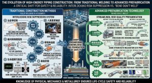
- 潁璋工程「能彎不銲」理念與三合一工法之核心價值 / Ying-Zhang Engineering’s “Bend-Instead-of-Weld” Concept and the Core Value of the 3-in-1 Method 為徹底發揮冷彎優勢並解決現場痛點,導入潁璋工程(Ying-Zhang Engineering)所提倡的「三合一工法」(3D/5D CNC 大半徑冷作彎管 + IH-PBHT 單管感應亞臨界彎後熱處理 + QR Code 雲端數位履歷),被視為是發揮大半徑優勢的唯一解方61。此工法管理的核心價值在於徹底落實「能彎不銲」的設計理念,從源頭將易受流體沖刷與疲勞破壞的銲縫轉化為連續平滑的母材彎曲段64。針對高能管線,此工法的執行不僅是製造手段的升級,更是嚴格對接 ASME B31.1 與 B31J 規範的合規性展現64。其具體包含三大核心技術: To thoroughly leverage the advantages of cold bending and resolve field pain points, adopting Ying-Zhang Engineering’s “3-in-1 Method” (3D/5D CNC large-radius cold bending + IH-PBHT single-pipe induction subcritical post-bend heat treatment + QR Code cloud digital resume) is regarded as the definitive solution61. The core managerial value of this methodology lies in rigorously executing the “bend-instead-of-weld” design philosophy, fundamentally transforming welds—highly susceptible to fluid erosion and fatigue—into continuous, smooth base-metal bends from the very source64. For HEP, executing this method is not merely an upgrade in manufacturing capability; it is a manifestation of strict compliance aligned with ASME B31.1 and B31J codes64. It comprises three core technologies:
- 3D/5D CNC 大半徑冷作彎管 (3D/5D CNC Large-Radius Cold Bending):利用高精度的數控成型,精準避開流體渦流脫落造成的共振區間(斯楚哈爾數 Strouhal Number 0.4~0.5),從物理幾何上消除銲縫弱點64。 / Utilizes high-precision CNC forming to accurately bypass the resonance interval caused by vortex shedding (Strouhal Number 0.4~0.5), physically and geometrically eliminating weld vulnerabilities64.
- IH-PBHT 單管感應亞臨界彎後熱處理 (IH-PBHT Single-Pipe Induction Subcritical Heat Treatment):針對高階合金鋼成型後的微觀組織劣化,進行極度精確的局部退火熱處理修復64。 / Conducts hyper-accurate localized annealing heat treatment to repair microstructural degradation in advanced alloy steels post-forming64.
- QR Code 雲端數位履歷系統 (QR Code Cloud Digital Resume System):將每一段管件的材料證明、冷彎幾何參數與 IH-PBHT 熱處理溫度曲線無縫綁定於雲端。這使得 EPC 與廠務管理者能一鍵追溯所有品質數據,極大化地簡化了 ASME Form CC-1 / CC-2 的合規簽署流程62。 / Seamlessly binds material certs, cold-bend geometric parameters, and IH-PBHT thermal curves to the cloud for each pipe segment. This allows EPCs and plant managers to trace all quality data with a single click, maximally streamlining the ASME Form CC-1 / CC-2 compliance signature process62.
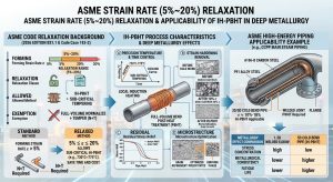
8.3 應變率 (5%~20%) 放寬與 IH-PBHT 適用之深度冶金解析 / 8.3 In-depth Metallurgical Analysis of Strain Rate (5%~20%) Relaxation and IH-PBHT Application
冷作彎管雖可免除銲接,但室溫下的巨量塑性變形會導致材料嚴重「應變硬化(Strain Hardening)」,造成差排密度激增與腐蝕電位(Ecorr)顯著負移60。對於 P-No.15E(如 Grade 91/92)這類對熱力學極度敏感的潛變強化鋼,如何進行彎後熱處理(PBHT)是決定其最終壽命的關鍵。While cold bending omits welding, massive plastic deformation at room temperature induces severe “Strain Hardening” in the material, triggering an exponential spike in dislocation density and a significant negative shift in corrosion potential (Ecorr)60. For thermodynamically hypersensitive creep-strengthened steels like P-No.15E (Grade 91/92), how Post-Bend Heat Treatment (PBHT) is conducted dictates their ultimate lifespan.
- 應變率放寬與 ASME Code Case 183-2 的法規依據 / Strain Rate Relaxation and ASME Code Case 183-2 Statutory Basis 依據力學幾何,冷作彎管的最大外緣應變率 ϵ 可概估為ϵ=r/R1 ×100% (r 為管外徑的一半,R1 為彎曲半徑)61。對於 5D 彎管(彎曲半徑為管外徑的 5 倍),其應變率約落在 10% 左右61。針對此區間,最新版的 ASME B31.1 Code Case 183-2 進行了極為關鍵的法規放寬:當冷作應變率介於5%≤ϵ≤20% 時,法規允許僅實施「局部次臨界回火(Subcritical Tempering PBHT,溫度區間 730°C 至 775°C)」,而無須進行整管的重新正常化與回火(N&T)64。Based on mechanical geometry, the maximum extrados forming strain rate ϵ of cold bends can be approximated as ϵ=r/R1 ×100% (r being half the outside diameter, R1 the bend radius)61. For 5D bends (bend radius is 5 times the pipe OD), the strain rate lands at roughly 10%61. Targeting this interval, the latest ASME B31.1 Code Case 183-2 provides a pivotal code relaxation: when cold forming strain is between 5%≤ϵ≤20%, the code permits local “Subcritical Tempering PBHT (temp range 730°C to 775°C)” without requiring full-pipe Renormalizing and Tempering (N&T)64.
- IH-PBHT 次臨界處理的微觀物理與 Larson-Miller 參數還原 / Micro-Physics of IH-PBHT Subcritical Processing and Larson-Miller Parameter Restoration 傳統銲接實務中,銲材常添加鎳(Ni)與錳(Mn),這會導致該區域材料的下臨界轉變溫度(AC1)大幅下探至 760°C 甚至更低61。若熱處理溫度過高跨越了AC1 線,材料基底將崩潰進入(沃斯田鐵+鐵素體)兩相區(Intercritical Region),冷卻後會生成極端硬脆的「鮮明未回火麻田散鐵(Fresh Martensite)」61。In traditional welding practices, filler metals frequently contain Nickel (Ni) and Manganese (Mn), which severely depress the material’s lower critical transformation temperature (AC1) in that zone to 760°C or even lower61. If heat treatment temperatures overshoot the AC1 line, the matrix collapses into the (Austenite + Ferrite) Intercritical Region; upon cooling, it generates extremely brittle “Fresh un-tempered Martensite”61.
針對 5D 彎管 10% 的應變率,潁璋工程的 IH-PBHT(單管感應亞臨界彎後熱處理)技術透過高頻電磁感應,提供了遠勝於傳統加熱毯的升降溫均勻度與精準溫控64。它能嚴格將溫度控制在 730°C 至 775°C 的次臨界範圍內,在不超越相變點誘發新麻田散鐵的前提下,有效消除冷作引發的差排網並穩定 M23C6 碳化物64。這種處理將受損金屬的拉森-米勒參數(Larson-Miller Parameter, LMP)完美恢復至安全區間,徹底確保了 P9x 高階合金鋼在未來幾十年承受反覆熱循環下的潛變抗力與系統完整性64。Addressing the 10% strain rate of 5D bends, Ying-Zhang Engineering’s IH-PBHT (Induction Heating Post-Bend Heat Treatment) utilizes high-frequency electromagnetic induction, delivering heating/cooling uniformity and precision vastly superior to traditional heating blankets64. It strictly reigns temperatures within the 730°C to 775°C subcritical zone. Without breaching the phase transformation point and triggering new martensite, it effectively annihilates cold-work-induced dislocation networks and stabilizes M23C6 carbides64. This processing immaculately restores the damaged metal’s Larson-Miller Parameter (LMP) to safe envelopes, resolutely assuring the creep resistance and system integrity of P9x advanced alloys under decades of thermal cycling64.
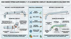
8.4 高能管線洩水坡度 (1°~3°) 設計下之幾何衝突與實務工法差異 / 8.4 Geometric Conflicts and Practical Method Differences under HEP Drainage Slope (1°~3°) Design
在工業蒸汽分配系統中,確保管線具備適當的洩水坡度(Drainage slope)是防止「凝結水誘發水錘現象」(Condensate Induced Water Hammer, CIWH)與流體加速腐蝕(FAC)的絕對必要條件66。ASME B31.1 與 B31.3 實務上通常要求蒸汽主管道與凝結水管線具備至少 1/8 英吋每英呎(即 1:96,約 0.6°)的坡度,而在某些高流速或需要克服流體拖曳力(Drag force)的嚴苛製程中,設計端更會指定 1° 至 3°(約 1.75% 至 5.2%)之非標準洩水坡度66。然而,此一設計要求在實務現場施作時,卻經常與傳統鍛造管件(銲接彎頭與套銲接頭)產生嚴重的幾何與法規衝突。In industrial steam distribution systems, ensuring adequate drainage slope is an absolute necessity to prevent “Condensate Induced Water Hammer (CIWH)” and Flow-Accelerated Corrosion (FAC)66. ASME B31.1 and B31.3 practically require steam mains and condensate lines to have a slope of at least 1/8 inch per foot (i.e., 1:96, approx. 0.6°). Moreover, in stringent processes with high velocities or where fluid drag forces must be overcome, design engineers frequently specify non-standard drainage slopes ranging from 1° to 3° (approx. 1.75% to 5.2%)66. However, implementing this design requirement in the field routinely triggers severe geometric and statutory conflicts with traditional forged fittings (welded elbows and socket-weld joints).
- 傳統套銲接頭 (Socket Weld Joints) 在洩水坡度下的困境 / The Dilemma of Traditional Socket Weld Joints Under Drainage Slopes 套銲接頭廣泛應用於 NPS 2 以下的小管徑高能管線中。ASME B31.1 第 127.3(e) 節強制規定,管子插入套筒底端後,必須向外拔出保持「約 1/16 英吋(1.6 mm)」的軸向間隙(Gap),以吸收銲接熱循環與服役期間的熱膨脹,避免疲勞裂紋25。 Socket weld joints are widely applied in small-bore HEP under NPS 2. ASME B31.1 Paragraph 127.3(e) mandatorily dictates that after bottoming out in the socket, the pipe must be withdrawn to maintain an axial gap of “approximately 1/16 inch (1.6 mm)” to absorb welding thermal cycles and in-service thermal expansion, thereby preventing fatigue cracks25.
然而,標準的套銲彎頭均為精準的 90° 或 45°。若為了營造 2° 的管線洩水坡度,配管人員必須在套筒內部將管子「傾斜(Tilt)」插入。這會導致管線外徑(OD)的單側死死抵住套筒內壁,而另一側則產生極大的空隙,徹底破壞了法規要求的均勻 1/16 英吋間隙27。這種幾何上的不對稱,不僅在系統升溫時會引發強烈的二次彎曲應力(Secondary bending stress)與熱疲勞(Thermal fatigue)69,其管端縫隙更容易成為積聚凝結水的死角,進一步誘發局部腐蝕與水錘破壞。However, standard socket weld elbows are forged precisely at 90° or 45°. To fabricate a 2° piping drainage slope, pipefitters must insert the pipe into the socket with a “tilt.” This causes one side of the pipe’s outside diameter (OD) to jam dead against the socket’s inner wall, while creating a massive void on the opposite side, completely destroying the uniformly distributed 1/16-inch gap demanded by code27. Such geometrical asymmetry not only induces intense secondary bending stress and thermal fatigue during system heat-up69, but the crevice at the pipe end also becomes a dead zone for condensate pooling, further instigating localized corrosion and water hammer destruction.
- 傳統電銲對接彎頭 (Butt-Welded Elbows) 的內部錯位 (Hi-Lo) 危機 / The Internal Misalignment (Hi-Lo) Crisis of Traditional Butt-Welded Elbows
對於 NPS 2 以上的管線,通常採用對接銲彎頭(電銲彎頭)。與套銲接頭類似,標準彎頭皆為 90° 成品。若要使其與具備 1°~3° 傾角的直管對接,會形成一個 V 字型的「角偏差(Angular offset)」。For piping above NPS 2, butt-welded elbows are generally employed. Similar to socket fittings, standard elbows are strictly 90° manufactured parts. Attempting to butt-weld them to a straight pipe pitched at a 1°~3° angle creates a V-shaped “angular offset.”
ASME B31.1 第 127.3 節嚴格限制內部錯位(Hi-Lo)最大不得超過 1/16 英吋,且根部間隙(Root gap)極限通常限制在 3/16 英吋以內22。若將大管徑(例如 10 吋)的直管傾斜 2° 對接於 90° 彎頭,其開口兩端的根部間隙差異將高達 0.35 英吋(約 9 mm)。這使得銲工根本無法進行符合 WPS 規範的打底銲(Root pass),極易產生未熔合(Lack of fusion)與過度穿透(Burn-through)等致命缺陷23。若要強行修正,現場只能對彎頭的端面進行非標準角度的斜切與重新車削坡口,此舉不僅耗工費時,更可能因切削過多而導致端部管壁低於最小需求厚度(tm),成為法規審查的重大違規。ASME B31.1 Paragraph 127.3 strictly limits internal misalignment (Hi-Lo) to a maximum of 1/16 inch, with root gaps generally limited to within 3/16 inch22. If a large-bore straight pipe (e.g., 10-inch) is pitched at 2° and abutted to a 90° elbow, the disparity in the root gap across the opening ends spikes to roughly 0.35 inches (approx. 9 mm). This renders welders entirely incapable of executing a WPS-compliant root pass, inviting fatal defects like lack of fusion and burn-through23. To forcibly rectify this on-site, crews must resort to non-standard miter cutting and re-machining of the elbow’s bevel face. This not only consumes excessive time and labor but also runs the heavy risk of over-machining, causing the end wall to dip below the minimum required thickness (tm)—constituting a major violation during statutory inspections.
- CNC 大曲率冷作彎管 (Cold-Formed Bends) 的根本性解方 / The Fundamental Solution of CNC Large-Radius Cold-Formed Bends
相較於傳統電銲彎頭與套銲接頭的幾何死局,3D/5D CNC 大曲率冷作彎管展現了無可比擬的實務優勢71。 Compared to the geometric dead-ends of traditional butt-welded and socket-welded elbows, 3D/5D CNC large-radius cold bends exhibit unparalleled practical supremacy71.
透過高精度的數位控制(CNC)彎管機,工程師可直接在工廠將無縫鋼管成型為完全符合設計需求之非標準角度(例如精準的 88.5° 或 92° 以完美匹配 1.5° 的洩水坡度)71。這種「任意角度成型」的工法帶來了兩大決定性好處: Via high-precision CNC bending machines, engineers can form seamless pipe in the factory to non-standard angles that flawlessly match design requirements (e.g., precisely 88.5° or 92° to perfectly accommodate a 1.5° drainage slope)71. This “arbitrary angle forming” capability yields two decisive advantages:
- 消除裝配應力與銲道缺陷 (Elimination of Fit-up Stress and Weld Defects):彎管兩端的直管段(Tangent length)可與相鄰管線保持絕對的 180° 同軸心對齊,根部間隙與 Hi-Lo 完美一致,使得現場銲口能輕鬆通過嚴格的 ASME B31.1 裝配寬容度審查與後續的 PAUT 非破壞檢測71。 / The tangent lengths at both ends of the bend can maintain absolute 180° coaxial alignment with adjoining pipes. Root gaps and Hi-Lo are perfectly consistent, allowing field welds to effortlessly pass strict ASME B31.1 fit-up tolerance checks and subsequent PAUT examinations71.
- 優化流場與徹底消除積水死角 (Optimization of Flow Field and Eradication of Pooling Dead Zones):冷彎一體成型的平滑內弧,徹底消滅了套銲接頭的縫隙與傳統銲接彎頭的銲渣突起,為蒸汽凝結水提供了一條無阻礙的層流(Laminar flow)排放路徑68。這從物理源頭上消除了凝結水滯留的可能,最大幅度地降低了高能管線發生凝結水誘發水錘(CIWH)與沖蝕的工安風險。 / The smooth inner arc of the integral cold bend completely eradicates the crevices of socket joints and the weld slag protrusions of traditional elbows, furnishing an unobstructed laminar flow drainage path for steam condensate68. This structurally neutralizes the possibility of condensate pooling at the physical source, maximally suppressing the industrial safety risks of CIWH and erosion in HEP.
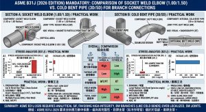
8.5 2026版 ASME B31J 強制導入下:支管 1.0D/1.5D 套銲彎頭與 3D/5D 冷作彎管之應力與實務工法差異 / 8.5 Under the 2026 Mandatory Implementation of ASME B31J: Stress and Practical Method Differences Between 1.0D/1.5D Socket Elbows and 3D/5D Cold Bends for Branch Piping
在2026版 ASME B31J(管線幾何與應力強度因子規範)的強制導入下,高能管線系統的應力分析標準發生了典範轉移。特別是針對公稱管徑 NPS 2 以下的支管(Branch pipes)系統,傳統高度依賴的 1.0D 與 1.5D 套銲彎頭(Socket-welded elbows)在面對嚴苛的應力計算與熱疲勞檢驗時,暴露出極大的實務侷限性,而 3D/5D 大半徑冷作彎管則成為最佳的替代解方。Under the mandatory implementation of the 2026 edition of ASME B31J (Standard for Standardized Method to Develop Stress Intensification Factors and k-Factors for Piping Components), the stress analysis benchmarks for HEP systems have undergone a paradigm shift. Particularly for branch piping systems below NPS 2, the traditionally heavily relied-upon 1.0D and 1.5D socket-welded elbows expose massive practical limitations when confronting grueling stress calculations and thermal fatigue inspections, positioning 3D/5D large-radius cold bends as the optimal alternative solution.
- 1.0D & 1.5D 套銲彎頭在 ASME B31J 下的應力與裝配挑戰 / Stress and Fit-up Challenges of 1.0D & 1.5D Socket Elbows under ASME B31J
套銲彎頭長期以來被廣泛用於小管徑支管的轉向設計,但依據最新的 ASME B31J 規範指出,短半徑(如 1.0D 或 1.5D)彎頭具備極高的應力強度因子(SIF)。為了在極端的熱膨脹與高壓環境下維持壓力邊界的安全,1.5D 彎頭的母材必須額外補償約 19% 至 25% 的厚度裕度61。 Socket elbows have long been widely utilized for directional changes in small-bore branches. Yet, the latest ASME B31J code specifies that short-radius (e.g., 1.0D or 1.5D) elbows command extremely high Stress Intensification Factors (SIF). To sustain pressure boundary safety under extreme thermal expansion and high-pressure environments, the base material of a 1.5D elbow must compensate with an additional thickness margin of roughly 19% to 25%61.
更嚴峻的挑戰在於現場裝配。誠如 8.4 節所述,依據 ASME B31.1 第 127.3(e) 節的強制規定,套銲接頭施銲前,管端插入套筒後必須向外拔出(Withdrawn)以保持約 1/16 英吋(1.6 mm)的軸向膨脹間隙(Gap)25。此間隙的物理意義在於吸收銲接熱循環與服役期間的高溫熱膨脹;若未確實留設此間隙(即所謂的 Zero gap),在系統升溫時,管端將死死頂住套筒底部,產生極大的干涉應力與二次彎曲應力(Secondary bending stress)25。在反覆熱循環下,這將誘發高週期的熱疲勞(Thermal fatigue)裂紋。然而,在狹窄且複雜的支管現場施工中,要精準維持這 1/16 英吋的間隙且通過品保查驗極度困難,加上裝配對心不良極易引入額外的二次彎曲應力,這使得傳統套銲接頭成為核電廠與火力電廠管線中最常發生穿牆洩漏(Through-wall leakage)的致命弱點25。An even grimmer challenge lies in field fit-up. As outlined in Section 8.4, per the mandatory dictates of ASME B31.1 Paragraph 127.3(e), before welding socket joints, the pipe end must be withdrawn after insertion to preserve an axial expansion gap of roughly 1/16 inch (1.6 mm)25. The physical purpose of this gap is to absorb welding thermal cycles and high-temperature thermal expansion during service. If this gap is not verifiably maintained (i.e., a “Zero gap”), system heat-up will cause the pipe end to forcibly ram against the socket bottom, sparking immense interference stress and secondary bending stress25. Under repetitive thermal cycling, this incites high-cycle thermal fatigue cracks. However, accurately maintaining this 1/16-inch gap and passing QA inspections in cramped and complex branch piping field installations is notoriously difficult. Coupled with the fact that poor alignment effortlessly introduces supplemental secondary bending stresses, traditional socket joints have notoriously become the most frequent origin of through-wall leakage vulnerabilities in nuclear and fossil power plant piping25.
- 3D/5D 冷作彎管工法之 SIF 解耦與疲勞防禦 / SIF Decoupling and Fatigue Defense via 3D/5D Cold Bending Methods
相較之下,將支管直接以 3D 或 5D CNC 冷作彎管一體成型,完美解決了上述的應力與裝配難題。By contrast, integrally forming the branch pipe directly via 3D or 5D CNC cold bending flawlessly resolves the aforementioned stress and fit-up conundrums.
在 ASME B31J 的應力計算中,5D 冷作彎管的 SIF 值幾乎逼近於 1.0(等同於直管的受力狀態)。其成型過程中外弧側的微小減薄量,完全可被標準無縫管材自帶的 12.5% 製造負容許差所吸收,無須像 1.5D 彎頭那樣進行額外的厚度補償12。 In ASME B31J stress calculations, the SIF value of a 5D cold bend approximates 1.0 (equating to the stress state of straight pipe). The minuscule extrados thinning during forming is entirely absorbed by the standard seamless pipe’s inherent 12.5% negative mill tolerance, circumventing the need for supplementary thickness compensation as mandated for 1.5D elbows12.
在實務工法上,採用冷作彎管直接消滅了支管轉向處的套銲銲道,徹底排除了 1/16 英吋膨脹間隙難以控制的人為失誤風險與品管盲區。由於從物理幾何上消除了套筒內部的縫隙與間隙死角,不僅免除了二次彎曲應力所帶來的疲勞破壞風險,同時也避免了高流速流體在縫隙處產生局部沖蝕。此一工法差異,大幅提升了支管系統在高溫振動環境下的全生命週期可靠度,也完全呼應了「能彎不銲」的核心價值。In practical methodology, deploying cold bends eradicates the socket weld at the branch directional change, permanently eliminating the human error risks and QA blind spots associated with the elusive 1/16-inch expansion gap. By physically and geometrically abolishing the internal socket crevice and gap dead-zone, it not only dispenses with the fatigue destruction risks borne of secondary bending stresses but also precludes localized erosion from high-velocity fluids at the crevice. This methodological divergence massively boosts the full lifecycle reliability of branch systems in high-temperature vibrational environments, flawlessly echoing the core virtue of “bend-instead-of-weld.”
九、 結論 / IX. Conclusion
高能管線(HEP)系統的安全建造,建立在固態力學、物理冶金學、流體力學與熱力學的深度交叉應用之上。本研究透過分析傳統配管工法之標準作業程序,並納入先進工法的演進,得出以下核心技術洞察:The safe construction of High Energy Piping (HEP) systems is founded on the deep interdisciplinary application of solid mechanics, physical metallurgy, fluid mechanics, and thermodynamics. Through the analysis of traditional piping standard operating procedures and the inclusion of advanced methodological evolutions, this study derives the following core technical insights:
- 設計與破壞防禦的數學關聯性 (Mathematical Correlation of Design and Failure Defense):ASME B31.1 第1.2 節中的壁厚力學模型,不僅僅是幾何尺寸的計算,更是藉由溫度係數(y)與銲縫強度折減係數(W),成功地將微觀的材料潛變劣化機制,轉換為巨觀的幾何設計補償,並突顯了忽略軋製容許差的危險性。 / The wall thickness mechanical model in ASME B31.1 Paragraph 104.1.2 is not merely a geometric calculation. Through the temperature coefficient (y) and weld strength reduction factor (W), it successfully translates microscopic material creep degradation mechanisms into macroscopic geometric design compensations, highlighting the danger of ignoring mill under-tolerance.
- 變數控制的嚴密冶金學意義 (Rigorous Metallurgical Significance of Variable Control):ASME Section IX 的 PQR/WPS 制度絕非單純的文件審查,而是針對「基本變數」進行嚴格的物理熱力學邊界控制。數位化溫度與熱輸入監控的導入,有效防止了熱影響區麻田散鐵脆化與氫誘發裂紋的發生。 / The PQR/WPS system in ASME Section IX is far from a simple document review; it is a strict physical and thermodynamic boundary control over “essential variables.” The integration of digital temperature and heat input monitoring effectively prevents HAZ martensitic embrittlement and hydrogen-induced cracking.
- 高階合金鋼的潛變脆弱性 (Creep Vulnerability of Advanced Alloy Steels):以 Grade 91 為代表的高階耐熱鋼雖具備優異高溫強度,但其對銲接熱循環極度敏感。銲後熱處理(PWHT)的溫度梯度與持溫時間若執行不當,將直接導致細晶區(FGHAZ)的碳化物粗化,引發致命的 Type IV 潛變裂紋。Larson-Miller 參數的應用,在數學上證明了精確控制運轉溫度對於指數級延長管線壽命的絕對必要性。 / Despite superior high-temperature strength, advanced heat-resistant steels like Grade 91 are hyper-sensitive to welding thermal cycles. Improper PWHT temperature gradients and holding times directly trigger carbide coarsening in the FGHAZ, inciting fatal Type IV creep cracking. The Larson-Miller Parameter mathematically proves the absolute necessity of precise operational temperature control to exponentially prolong piping life.
- 工程實務的典範轉移「能彎不銲」 (Paradigm Shift in Engineering Practice “Bend-Instead-of-Weld”):綜合業主、EPC、廠務及協力廠商的需求,以 3D/5D CNC 冷彎結合 IH-PBHT 的「三合一工法」解決了傳統厚壁銲接在 SIF 應力集中與 Type IV 裂紋上的先天劣勢。ASME 應變率放寬(5%≤ϵ≤20%)在法規層面賦予了此工法正當性,而數位化履歷的導入更將 Form CC-1 / CC-2 的合規難度降至最低。 / Reconciling the needs of owners, EPCs, plant managers, and subcontractors, the “3-in-1 method” (3D/5D CNC cold bending + IH-PBHT) resolves the innate detriments of SIF stress concentration and Type IV cracking in traditional thick-wall welds. ASME’s strain rate relaxation (5%≤ϵ≤20%) grants this methodology statutory legitimacy, while digital resumes minimize Form CC-1/CC-2 compliance friction.
- 技術革新與調試的極致嚴謹性 (Extreme Rigor in Technological Innovation and Commissioning):非破壞檢驗技術從 RT 向 PAUT 與 TOFD 的演進,象徵著對體積型缺陷的判定由「二維衰減投影」正式邁向「三維斷裂力學定量」的跨越。而在最終的蒸汽吹管調試階段,嚴格遵守 CFR > 1.0 的流體動量條件與標靶板微米級的表面驗收,為機組的穩定運轉提供了最後且最關鍵的一道防線。 / The evolution of NDE from RT to PAUT/TOFD signifies the leap from “2D attenuation projection” to “3D fracture mechanics quantification” in evaluating volumetric defects. In the final steam blowing commissioning phase, strict adherence to CFR > 1.0 fluid momentum conditions and micro-level target plate acceptance provides the final, most critical line of defense for stable unit operation.
綜上所述,傳統配管工法在高能管線中的各項標準作業程序,實際上是一套環環相扣的極端風險抑制體系。隨著工程環境的嚴苛化,從傳統工法向「能彎不銲」先進預製技術的過渡已成必然趨勢。工程實務操作者必須對法規背後的物理力學與冶金學原理具備深刻認知,方能確保高能管線生命週期之絕對安全與可靠度。In summary, the standard operating procedures of traditional piping fabrication in high energy piping represent an interlocking, extreme-risk suppression system. As engineering environments become more grueling, the transition from traditional methods to advanced “bend-instead-of-weld” prefabrication technologies has become an inevitable trend. Field practitioners must possess a profound comprehension of the underlying physical mechanics and metallurgical principles behind the codes to ensure the absolute safety and reliability of the high energy piping lifecycle.
參考文獻 / References
- ASME B31.1 Power Piping Code 2026 — Inspection Requirements, https://atlantisndt.com/blog/asme-b31-1-power-piping-code-explained
- ASME Section I and B31.1 – Power Boilers and Components (E25), https://www.munichre.com/content/dam/munichre/hsb/hsb-iic/documents/hsb-gies-asme-section-i-b31-1-e25.pdf/_jcr_content/renditions/original.media_file.download_attachment.file/hsb-gies-asme-section-i-b31-1-e25.pdf
- ASME-B31.1.pdf – Future Energy Steel, https://energy-steel.com/wp-content/uploads/2025/03/ASME-B31.1.pdf
- ASME B31.1 (2007): Code for Pressure Piping, Power Piping, https://dl.icdst.org/pdfs/files/69958bb53255b2716e28067c6e7671cb.pdf
- Piping Materials and Allowable Stress in ASME B31.1 Power Piping, https://mypipingnotes.com/asme-b31-1-materials-allowable-stress/
- ASME B31.1 對3 管線規範選擇指南| IMD, https://industrialmonitordirect.com/zh-hant/blogs/knowledgebase/asme-b311-vs-b313-piping-code-selection-guide
- ASME B31.1 Power Piping: Welding, Examination & Acceptance, https://www.therness.com/blog/asme-b31-1-power-piping-welding-examination-acceptance-guide/
- ASME B31.1 Power Piping WPS Requirements Explained, https://wpswelding.com/blog/asme-b31-1-power-piping-weld-procedure-requirements
- ASME Section V NDE — Complete Code Overview | WeldFabWorld, https://www.weldfabworld.com/asme-section-v/
- What is the ASME B31.1 Power Piping Code and What is New?, https://epcland.com/asme-b31-1-power-piping-code/
- Pipe Welding & Pressure Testing – FabTek Industries, https://fabtekindustries.com/pipe-welding-pressure-testing
- ASME B31.1 Wall Thickness Calculator — ¶104.1.2 – Piping Toolset, https://pipingtoolset.com/calculators/b311-pipe-wall-thickness/
- ASME B31.1 Power Piping: Examination and Acceptance, https://atlantisndt.com/standards/asme-b31-1
- Pipe Wall Thickness Calculator — ASME B31.3 & B31.1, https://www.weldfabworld.com/pipe-wall-thickness-calculator/
- Weld Strength Reduction Factors Guide | PDF – Scribd, https://www.scribd.com/document/935193206/ASME-Sec-I-2025-82
- EPRI – Guided For Piping Stress Analysis | PDF – Scribd, https://www.scribd.com/document/750085015/EPRI-Guided-for-piping-stress-analysis
- Weld Joint Strength Reduction Factor — ASME B31.3 – WeldFabWorld, https://www.weldfabworld.com/weld-joint-strength-reduction-factor-w/
- 1 Pipe Pressure and Thickness Data | PDF – Scribd, https://www.scribd.com/document/366952150/Pipes-Pressure-and-wall-thickness-equations-and-data-for-a-straight-pipe-ASME-B31-1-and-B31-3-ods
- Piping Wall Thickness Calculation Guide | PDF – Scribd, https://www.scribd.com/doc/208094922/Pipe-Wall-Thickness
- 2026 版ASME B31.1與3 壓力管線規範分析:冷彎成型, https://yz-pipe-bending.com.tw/2026-%E7%89%88asme-b31-1%E8%88%87b31-3-%E5%A3%93%E5%8A%9B%E7%AE%A1%E7%B7%9A%E8%A6%8F%E7%AF%84%E5%88%86%E6%9E%90%EF%BC%9A%E5%86%B7%E5%BD%8E%E6%88%90%E5%9E%8B%E3%80%81%E5%BE%8C%E7%86%B1%E8%99%95/
- 2026 ASME 規範架構下1 & B31.3 成型應變率之深度剖析, https://yz-pipe-bending.com.tw/2026-asme-%E8%A6%8F%E7%AF%84%E6%9E%B6%E6%A7%8B%E4%B8%8B-b31-1-b31-3-%E6%88%90%E5%9E%8B%E6%87%89%E8%AE%8A%E7%8E%87%E4%B9%8B%E6%B7%B1%E5%BA%A6%E5%89%96%E6%9E%90%EF%BC%9A5d-%E5%86%B7%E4%BD%9C%E5%BD%8E/
- ASME B31 Piping Welding Standards | PDF – Scribd, https://www.scribd.com/document/290016915/WFP-2-01-Procedure-R1
- Weld Joint Preparation According to ASME B31.3 and B31.1, https://gbcspa.com/en/weld-joint-preparation-asme-b31/
- Saes L 350 | PDF | Pipe (Fluid Conveyance) | Steam – Scribd, https://www.scribd.com/document/1025630468/SAES-L-350
- Analysis of Socket Welded Assembly Gap – EPRI, https://restservice.epri.com/publicdownload/000000000001009715/0/Product
- Socket Weld Integrity in Nuclear Piping under Fatigue Loading, https://www.researchgate.net/publication/243761332_Socket_Weld_Integrity_in_Nuclear_Piping_under_Fatigue_Loading_Condition
- Socket Welding Guide: ASME B16.11 Standards, Pressure Classes, https://baling-steel.com/socket-welding-guide/
- ASME Section IX: WPS, PQR and Essential Variables – Atlantis NDT, https://atlantisndt.com/standards/asme-section-ix
- What is ASME Section IX and its Overview of subsections … – Let’sFab, https://letsfab.in/asme-section-ix/
- WPS, PQR & Welder Qualification: ASME Section IX Explained | Blog, https://www.kaskomakine.com/blogs/wps-pqr-welder-qualification-asme-section-ix
- ASME Section IX: which essential variables force a new PQR, https://www.therness.com/blog/asme-section-ix-welding-procedure-qualification-digital-monitoring/
- ASME Section IX Variable Types: Essential vs Nonessential, https://wpswelding.com/blog/asme-ix-three-variable-types-qw-250
- ASME Section IX: WPS and PQR Guidelines | PDF – Scribd, https://www.scribd.com/document/711893032/ASME-SEC-9-ARTICLE-2-Welding-procedure-qualification
- ASME B31.1 PWHT Requirements – Table 132 | WeldFabWorld, https://www.weldfabworld.com/asme-b31-1-pwht-requirements/
- ASME B31P Standard on Preheat & PWHT | PDF – Scribd, https://www.scribd.com/document/244267499/Proposed-New-ASMEB31P-Standard-On-Preheat-PWHT-pdf
- P91高合金耐熱鋼二次熱處理之潛變退化機制與CCPP高能管線以彎代, https://yz-pipe-bending.com.tw/p91%E9%AB%98%E5%90%88%E9%87%91%E8%80%90%E7%86%B1%E9%8B%BC%E4%BA%8C%E6%AC%A1%E7%86%B1%E8%99%95%E7%90%86%E4%B9%8B%E6%BD%9B%E8%AE%8A%E9%80%80%E5%8C%96%E6%A9%9F%E5%88%B6%E8%88%87ccpp%E9%AB%98%E8%83%BD/
- GUIDE LINES FOR HEAT TREATMENT – BHEL, https://www.bhel.com/sites/default/files/sct-1867-nit-volume-1a-techno-commercial-bid_part3-1572614268.pdf
- The Effect of Normalizing Temperature on the Short-Term Creep, https://www.mdpi.com/2075-4701/8/12/1072
- Effect of Postweld Heat Treatments on Type IV Creep Failure … – MDPI, https://www.mdpi.com/2075-4701/11/5/726
- Review of Type IV Cracking in Piping Welds – EPRI, https://restservice.epri.com/publicdownload/TR-108971/0/Product
- Type IV Cracking of Weldments in Enhanced Ferritic Steels – TWI, https://www.twi-global.com/technical-knowledge/published-papers/review-of-type-iv-cracking-of-weldments-in-9-12cr-creep-strength-enhanced-ferritic-steels/
- Analysis of Cracking Causes of P91 Welding Seam of High Pressure, https://www.researchgate.net/publication/349983446_Analysis_of_Cracking_Causes_of_P91_Welding_Seam_of_High_Pressure_Steam_Guide_Pipe_of_Supercritical_Unit
- (PDF) Insight into Type IV cracking in Grade 91 steel weldments, https://www.researchgate.net/publication/339358586_Insight_into_Type_IV_cracking_in_Grade_91_steel_weldments
- The impact of weld metal creep strength on the overall … – SciSpace, https://scispace.com/pdf/the-impact-of-weld-metal-creep-strength-on-the-overall-creep-3b7fq92ycm.pdf
- Creep Life — Larson-Miller Parameter Calculator — How to Use It, https://www.youtube.com/watch?v=bvxafXC-hic
- Creep Life — Larson-Miller Parameter Calculator — How to Use It, https://www.youtube.com/watch?v=y51IKKr1o0g
- Creep Life Calculator — Larson-Miller Parameter, https://www.firgelliauto.com/blogs/engineering-calculators/creep-life-calculator-larson-miller-parameter-1
- Larson Miller Parameter for the Prediction of the Creep Life … – UTHM, https://journal.uthm.edu.my/index.php/ijie/article/view/13025
- ASME Section V Article 4 Overview | PDF – Scribd, https://www.scribd.com/document/494220539/Asme-v-Article-4
- Ultrasonic Examination of Welds as per ASME Boiler and Pressure, https://www.onestopndt.com/ndt-articles/ultrasonic-testing-of-welds-asme-bpvc
- Code case 181 | PDF – Slideshare, https://www.slideshare.net/slideshow/code-case-181/78480947
- AATA 104B: ULTRASONIC PHASED ARRAY LABORATORY, https://catalog.foothill.edu/course-outlines/AATA-104B/AATA-104B.pdf
- 2025 版ASME鍋爐與壓力容器規範及B31 系列重大修訂, https://yz-pipe-bending.com.tw/2025-%E7%89%88-asme%E9%8D%8B%E7%88%90%E8%88%87%E5%A3%93%E5%8A%9B%E5%AE%B9%E5%99%A8%E8%A6%8F%E7%AF%84%E5%8F%8A-b31-%E7%B3%BB%E5%88%97%E9%87%8D%E5%A4%A7%E4%BF%AE%E8%A8%82%EF%BC%9A%E5%B0%88%E6%A5%AD/
- best practice for commissioning steam and air line blowing, https://www.researchgate.net/publication/376687382_BEST_PRACTICE_FOR_COMMISSIONING_STEAM_AND_AIR_LINE_BLOWING
- How to Clean Natural Gas Piping with Gas Blows – ResearchGate, https://www.researchgate.net/publication/340351792_How_to_Clean_Natural_Gas_Piping_with_Gas_Blows
- Steam Pipe Blowing Procedure Guide | PDF – Scribd, https://www.scribd.com/document/944392571/Col-obr-op2634-083-Steam-Pipe-Blowing
- Concentrating Solar Power Best Practices Study, https://docs.nlr.gov/docs/fy20osti/75763.pdf
- What is Steam Blowing and the Steam Blowing Procedure?, https://epcland.com/steam-blowing-procedure/
- C o m p a n y P r o f i l e – DB Holdings, http://dbholdings.asia/pw_board/myboard/upload/1-0ddaf26db20607e249ccdc6a77e4e879f.pdf
- 基於ASME B31J 規範之高能管線紊流與沖蝕腐蝕對比研究, https://yz-pipe-bending.com.tw/%E5%9F%BA%E6%96%BC-asme-b31j-%E8%A6%8F%E7%AF%84%E4%B9%8B%E9%AB%98%E8%83%BD%E7%AE%A1%E7%B7%9A%E7%B4%8A%E6%B5%81%E8%88%87%E6%B2%96%E8%9D%95%E8%85%90%E8%9D%95%E5%B0%8D%E6%AF%94%E7%A0%94%E7%A9%B6/
- 基於2026 ASME B31J規範之P91/P92/P93高壓蒸汽高能管線應力解耦, https://yz-pipe-bending.com.tw/%E5%9F%BA%E6%96%BC2026-asme-b31j%E8%A6%8F%E7%AF%84%E4%B9%8Bp91-p92-p93%E9%AB%98%E5%A3%93%E8%92%B8%E6%B1%BD%E9%AB%98%E8%83%BD%E7%AE%A1%E7%B7%9A%E6%87%89%E5%8A%9B%E8%A7%A3%E8%80%A6%E3%80%81%E4%B8%89/
- 迎戰1 Appendix Q/R 規範升級:NBEP 管線數位化品質管理體系, https://yz-pipe-bending.com.tw/%E8%BF%8E%E6%88%B0-b31-1-appendix-q-r-%E8%A6%8F%E7%AF%84%E5%8D%87%E7%B4%9A%EF%BC%9Anbep-%E7%AE%A1%E7%B7%9A%E6%95%B8%E4%BD%8D%E5%8C%96%E5%93%81%E8%B3%AA%E7%AE%A1%E7%90%86%E9%AB%94%E7%B3%BB%E5%BB%BA/
- 基於2026 ASME B31.1 與B31J 規範管線應力強化與全生命週期管理, https://yz-pipe-bending.com.tw/%E5%9F%BA%E6%96%BC-2026-asme-b31-1-%E8%88%87-b31j-%E8%A6%8F%E7%AF%84%E7%AE%A1%E7%B7%9A%E6%87%89%E5%8A%9B%E5%BC%B7%E5%8C%96%E8%88%87%E5%85%A8%E7%94%9F%E5%91%BD%E9%80%B1%E6%9C%9F%E7%AE%A1%E7%90%86-2/
- 2026版ASME B31J 強制導入下高能管線工程之典範轉移:基於1, https://yz-pipe-bending.com.tw/2026%E7%89%88-asme-b31j-%E5%BC%B7%E5%88%B6%E5%B0%8E%E5%85%A5%E4%B8%8B%E9%AB%98%E8%83%BD%E7%AE%A1%E7%B7%9A%E5%B7%A5%E7%A8%8B%E4%B9%8B%E5%85%B8%E7%AF%84%E8%BD%89%E7%A7%BB%EF%BC%9A%E5%9F%BA%E6%96%BC-b31/
- ASME B31.1 Case 183 Guidelines | PDF | Heat Treating – Scribd, https://www.scribd.com/document/357607731/code-case-183-2
- How to Perform Piping Slope Calculation for Industrial Systems, https://epcland.com/piping-slope-calculation/
- Industrial Pipe Slope: 1/8″ per Foot Drainage Standards | IMD, https://industrialmonitordirect.com/blogs/knowledgebase/pipe-slope-and-pitch-standards-for-industrial-drainage-applications
- 基於ASME 最新規範之主蒸汽管線支管線(4″含以下)防護策略與冷作, https://yz-pipe-bending.com.tw/%E5%9F%BA%E6%96%BC-asme-%E6%9C%80%E6%96%B0%E8%A6%8F%E7%AF%84%E4%B9%8B%E4%B8%BB%E8%92%B8%E6%B1%BD%E7%AE%A1%E7%B7%9A%E6%94%AF%E7%AE%A1%E7%B7%9A4%E5%90%AB%E4%BB%A5%E4%B8%8B%E9%98%B2%E8%AD%B7%E7%AD%96/
- Misalignment factors to affect the fatigue of welded load-carrying joints, https://research.unipd.it/retrieve/f8492040-d45c-40b5-998a-6506e09359fa/1-s2.0-S0142112323004978-main.pdf
- Minimum Distance Between Welds According to Standards (ASME, https://grabcad.com/tutorials/weld-spacing-minimum-distance-between-welds-according-to-standards-asme-api–1
- 簡述管線的電銲銲接工法與冷作彎管工法有何差異性?, https://yz-pipe-bending.com.tw/%E7%B0%A1%E8%BF%B0%E7%AE%A1%E7%B7%9A%E7%9A%84%E9%9B%BB%E9%8A%B2%E9%8A%B2%E6%8E%A5%E5%B7%A5%E6%B3%95%E8%88%87%E5%86%B7%E4%BD%9C%E5%BD%8E%E7%AE%A1%E5%B7%A5%E6%B3%95%E6%9C%89%E4%BD%95%E5%B7%AE%E7%95%B0/
- 基於ASME B31J 規範之電廠高能管線任意角度冷作彎管空間佈置與, https://yz-pipe-bending.com.tw/%E5%9F%BA%E6%96%BC-asme-b31j-%E8%A6%8F%E7%AF%84%E4%B9%8B%E9%9B%BB%E5%BB%A0%E9%AB%98%E8%83%BD%E7%AE%A1%E7%B7%9A%E4%BB%BB%E6%84%8F%E8%A7%92%E5%BA%A6%E5%86%B7%E4%BD%9C%E5%BD%8E%E7%AE%A1%E7%A9%BA%E9%96%93/