
一、 摘要與研究背景 / 1. Abstract and Research Background
在現代複循環發電廠(Combined Cycle Power Plant, CCPP)的熱回收蒸汽發生器(Heat Recovery Steam Generator, HRSG)系統中,高壓管線的完整性是決定電廠安全與運轉效率的基石。在這些涉及極端高溫、高壓水與濕蒸汽兩相流的複雜管網中,流動加速腐蝕(Flow-Accelerated Corrosion, FAC)與沖蝕腐蝕(Erosion-Corrosion, E-C)已成為導致管線金屬壁面減薄與突發性失效的最主要元凶。據統計,此類由化學與流體力學交織而成的降解機制,佔據了 HRSG 管線失效案例的 40% 以上1。管壁減薄往往在隱蔽狀態下進行,一旦厚度低於承受操作壓力的極限值,便會引發災難性的「破裂前未洩漏」(Break-before-leak)事故。例如 1986 年 Surry 核電廠發生的冷凝水管線破裂,瞬間釋放的高壓蒸汽造成了嚴重的人員傷亡4。 In the Heat Recovery Steam Generator (HRSG) systems of modern Combined Cycle Power Plants (CCPP), the integrity of high-pressure piping is the cornerstone determining plant safety and operational efficiency. In these complex piping networks involving extreme high temperatures, high-pressure water, and wet steam two-phase flows, Flow-Accelerated Corrosion (FAC) and Erosion-Corrosion (E-C) have become the primary culprits causing pipe metal wall thinning and sudden failures. According to statistics, such degradation mechanisms, intertwined with chemistry and fluid dynamics, account for over 40% of HRSG piping failure cases1. This type of wall thinning often occurs under concealed conditions; once the thickness falls below the critical limit to withstand operating pressure, it can trigger catastrophic “Break-before-leak” accidents. For instance, the rupture of a high-pressure condensate line at the Surry nuclear plant in 1986 instantly released high-pressure steam, resulting in severe casualties4.
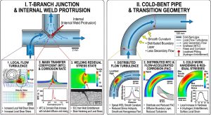
在 HRSG 系統的流體分配網路中,從主管(Header)分流至支管(Branch)的交接過渡區域,是流場擾動最為劇烈的節點。工程實務上,為實現流向轉換與分流,主要採用兩種結構特徵:其一為 T 型三通接頭或直接銲接分支,此種工法在根部極易伴隨「內突銲道」(Internal Weld Protrusion)的產生;其二則為減少銲縫數量及幾何不連續性,採用「冷作彎管」(Cold-Bent Pipe)進行過渡。傳統工程觀點多從巨觀的壓力降與施工便利性來評估這兩種工法,然而在微觀的材料降解層面,兩者對局部流場紊流(Turbulence)、壁面剪應力(Wall Shear Stress, WSS)、邊界層質傳係數(Mass Transfer Coefficient, MTC)以及金屬內部殘餘應力狀態的影響卻截然不同,並由此衍生出迥異的腐蝕失效模式。In the fluid distribution networks of HRSG systems, the transition area where fluid branches from the header to the branch pipe is the node with the most intense flow disturbance. In engineering practice, to achieve flow redirection and branching, two main structural features are utilized: the first is the T-junction or direct branch welding, a method highly prone to generating “Internal Weld Protrusions” at the root; the second is the use of “Cold-Bent Pipes” for the transition to reduce the number of welds and geometric discontinuities. Traditional engineering perspectives often evaluate these two methods from macroscopic pressure drops and construction convenience; however, at the microscopic material degradation level, their impacts on local flow turbulence, Wall Shear Stress (WSS), Mass Transfer Coefficient (MTC) in the boundary layer, and the internal residual stress state of the metal are vastly different, thereby deriving distinctly different corrosion failure modes.
本研究報告旨在透過嚴謹的學術論文架構,深入剖析流體動力學、熱力學、固體力學與材料微觀電化學之間的交互作用,全面對比探討「內突銲道」與「冷作彎管」在主管至支管過渡區的流場結構差異,並闡明兩者誘發流動加速腐蝕與沖蝕腐蝕的根本機制。透過深度的第二階與第三階學術洞察,本研究期能建立預測與防護管線局部減薄的科學理論基礎,為發電廠管線設計、材料選擇與非破壞性檢測(NDT)提供具體且具前瞻性的策略指引。This research report aims to deeply analyze the interactions among fluid dynamics, thermodynamics, solid mechanics, and material micro-electrochemistry through a rigorous academic paper framework. It comprehensively compares and explores the flow field structural differences between “internal weld protrusions” and “cold-bent pipes” in the transition zone from header to branch, and clarifies the fundamental mechanisms by which both induce flow-accelerated corrosion and erosion-corrosion. Through deep second-order and third-order academic insights, this study establishes a scientific theoretical foundation for predicting and preventing local wall thinning of pipelines, providing concrete and forward-looking strategic guidance for power plant piping design, material selection, and Non-Destructive Testing (NDT).
二、 管線降解之基礎理論與微觀動力學 / 2. Basic Theory and Micro-Dynamics of Pipeline Degradation
要精確對比不同幾何特徵下的材料流失行為,首要之務在於釐清流動加速腐蝕(FAC)與沖蝕腐蝕(E-C)在物理化學本質上的根本區別,並建立流場與質傳的數學模型。To accurately compare material loss behaviors under different geometric features, the primary task is to clarify the fundamental physical and chemical distinctions between Flow-Accelerated Corrosion (FAC) and Erosion-Corrosion (E-C), and to establish mathematical models for flow fields and mass transfer.
2.1 流動加速腐蝕(FAC)之電化學與質傳機制 / 2.1 Electrochemical and Mass Transfer Mechanisms of Flow-Accelerated Corrosion (FAC)
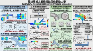
流動加速腐蝕(FAC)並非純粹的機械性磨損,而是一種由電化學溶解與流體質量傳遞共同驅動的過程,主要影響輸送高純度、去氧水或濕蒸汽的碳鋼與低合金鋼管線4。在停滯或低速的水環境中,碳鋼表面會自發生成一層具有高度保護性的磁鐵礦(Fe3O4)氧化膜,顯著降低金屬的腐蝕速率。然而,當流體以較高速度或強烈紊流流經管壁時,邊界層(Boundary Layer)內的質量傳遞速率急遽上升,加速了磁鐵礦向流體中溶離的過程7。 Flow-Accelerated Corrosion (FAC) is not purely mechanical wear but a process driven jointly by electrochemical dissolution and fluid mass transfer, primarily affecting carbon steel and low-alloy steel pipelines transporting high-purity, deoxygenated water or wet steam4. In stagnant or low-velocity aqueous environments, a highly protective magnetite (Fe3O4) oxide film spontaneously forms on the carbon steel surface, significantly reducing the metal’s corrosion rate. However, when fluid flows along the pipe wall at high velocities or with intense turbulence, the mass transfer rate within the boundary layer increases sharply, accelerating the dissolution of magnetite into the fluid7.
為了維持氧化層的再生以達成化學平衡,底層的金屬基體必須持續發生陽極溶解,從而導致管壁不斷減薄8。磁鐵礦的溶解度與系統溫度及 pH 值呈現非線性關係。在常規的電廠水化學條件下,磁鐵礦的溶解度約在 150°C 時達到峰值,這也解釋了為何特定溫度的省煤器(Economizer)與預熱器管線特別容易成為 FAC 的重災區9。當系統中的流體溶氧量極低時,FAC 速率會顯著上升;反之,若在水中加入微量氧氣或將 pH 值提升至 9.2 至 9.8 之間,則可促進更穩定的三價鐵氧化物形成,從而抑制 FAC 的進行6。 To maintain the regeneration of the oxide layer and achieve chemical equilibrium, the underlying metal matrix must undergo continuous anodic dissolution, leading to continuous wall thinning8. The solubility of magnetite exhibits a non-linear relationship with system temperature and pH. Under conventional power plant water chemistry conditions, magnetite solubility reaches its peak at approximately 150°C, which explains why economizer and preheater pipelines at specific temperatures are particularly prone to becoming FAC disaster zones9. When the dissolved oxygen content in the system fluid is extremely low, the FAC rate rises significantly; conversely, adding trace amounts of oxygen to the water or raising the pH to between 9.2 and 9.8 can promote the formation of more stable trivalent iron oxides, thereby inhibiting FAC progression6.
2.2 沖蝕腐蝕(Erosion-Corrosion)之機械破壞協同效應 / 2.2 Synergistic Effects of Mechanical Destruction in Erosion-Corrosion (E-C)
有別於 FAC 的化學主導特性,沖蝕腐蝕(E-C)包含了更為強烈的機械破壞成分。沖蝕腐蝕發生在流體與表面之間具有極高相對速度、流向劇烈改變,或是流體中夾帶兩相微滴(如濕蒸汽中的水滴)與懸浮固體顆粒的環境中7。流體流動產生的極高剪應力會直接將金屬表面的保護性氧化膜以物理方式剝離(Spalling),甚至直接將剛游離的金屬離子掃刷而去,使其無法在表面沉積形成保護層11。 Distinct from the chemistry-dominated nature of FAC, Erosion-Corrosion (E-C) contains a much stronger mechanical destruction component. Erosion-corrosion occurs in environments with extremely high relative velocities between the fluid and the surface, drastic changes in flow direction, or fluids carrying two-phase droplets (such as water droplets in wet steam) and suspended solid particles7. The extremely high shear stress generated by fluid flow will directly physically strip away (spall) the protective oxide film on the metal surface, or even directly sweep away newly ionized metal ions before they can deposit to form a protective layer11.
在這種機械剝離與腐蝕環境的協同作用(Synergistic effect)下,材料的流失速率遠大於單純腐蝕與單純沖蝕速率的加總。相較於 FAC 常見的橘皮狀或扇貝形表面,沖蝕腐蝕造成的表面損傷更具方向性,通常呈現與流場流線平行的深溝槽(Grooves)、波浪紋或圓形穿孔11。 Under this synergistic effect of mechanical spalling and corrosive environments, the material loss rate is far greater than the sum of simple corrosion and simple erosion rates. Compared to the orange-peel or scalloped surfaces commonly seen in FAC, surface damage caused by erosion-corrosion is more directional, usually presenting as deep grooves, wavy patterns, or circular holes parallel to the flow streamlines11.
2.3 質傳係數與紊流動能之邊界層類比模型 / 2.3 Boundary Layer Analogy Model for Mass Transfer Coefficient and Turbulent Kinetic Energy
不論是 FAC 還是 E-C,局部材料流失速率均高度依賴於流體邊界層內的質量傳遞效率。在紊流流場中,壁面與流體之間的離子質量傳遞可透過 Chilton-Colburn 類比方程式,將動量傳遞與質量傳遞進行數學關聯。質傳係數(Mass Transfer Coefficient, km)通常透過無因次群 Sherwood 數(Sh)來描述14: Whether it is FAC or E-C, the local material loss rate highly depends on the mass transfer efficiency within the fluid boundary layer. In a turbulent flow field, the ionic mass transfer between the wall and the fluid can be mathematically correlated with momentum transfer and mass transfer through the Chilton-Colburn analogy equation. The Mass Transfer Coefficient (km) is usually described by the dimensionless Sherwood number (Sh)14:
Sh=(kmd)/Dm =C⋅Rea⋅Scb
方程式中,d 為流場的特徵長度(如管線內徑),Dm 為金屬離子在特定流體中的擴散係數,Re 為雷諾數(代表流場慣性力與黏滯力之比,反映流速與紊流程度), Sc為施密特數(Schmidt number),而 C、a、b 為由幾何形狀與流態決定的經驗常數。對於管內完全發展的紊流,指數 a 介於 0.8 至 1.0 之間;然而,在產生流場分離與重新附著的區域,指數 a 甚至可超過 1.0,顯示質傳對流速變化的極度敏感11。 In the equation, d is the characteristic length of the flow field (e.g., pipe inner diameter), Dm is the diffusion coefficient of metal ions in the specific fluid, Re is the Reynolds number (representing the ratio of inertial forces to viscous forces in the flow field, reflecting flow velocity and turbulence level), Sc is the Schmidt number, and C, a, and b are empirical constants determined by geometry and flow regime. For fully developed turbulent flow inside a pipe, the exponent a ranges between 0.8 and 1.0; however, in regions where flow separation and reattachment occur, the exponent a can even exceed 1.0, indicating the extreme sensitivity of mass transfer to changes in flow velocity11.
當流場遭遇幾何不連續(如內突銲道或冷彎管的曲率變化)時,紊流動能(Turbulent Kinetic Energy, k)與雷諾應力(Reynolds Stress)會顯著上升。這些強烈的紊流擾動會壓縮層流黏滯次層(Laminar Viscous Sublayer)的厚度,導致邊界層內的濃度梯度急遽增大。隨著局部質傳係數 km 呈現指數型攀升,流體能以極高的效率將溶解的鐵離子帶入主流區,使得金屬表面的離子濃度始終遠低於其溶解度極限,進而使腐蝕反應處於最大驅動力狀態6。 When the flow field encounters geometric discontinuities (such as the curvature changes of internal weld protrusions or cold-bent pipes), the Turbulent Kinetic Energy (k) and Reynolds Stress will increase significantly. These strong turbulent disturbances compress the thickness of the laminar viscous sublayer, causing the concentration gradient within the boundary layer to increase sharply. As the local mass transfer coefficient km climbs exponentially, the fluid can highly efficiently carry dissolved iron ions into the mainstream, keeping the ion concentration at the metal surface consistently far below its solubility limit, thereby pushing the corrosion reaction to its maximum driving force state6.
三、 主管至支管分流管網之巨觀流體力學特徵 / 3. Macroscopic Fluid Dynamics Characteristics of Header-to-Branch Diverging Pipe Networks
在探討微觀腐蝕機制之前,必須先理解流體從主管分流至支管時的巨觀流體力學行為。這種分流 T 型接頭(Tee Junction)或歧管結構,在流體力學上被定義為分流流場(Dividing Flow)或發散管網(Diverging Manifold)。Before exploring microscopic corrosion mechanisms, it is necessary to understand the macroscopic fluid dynamics behavior when fluid branches from a header into a branch pipe. Such diverging T-junctions or manifold structures are defined in fluid mechanics as dividing flow or diverging manifolds.
3.1 分流管網之壓力變化與白努利效應 / 3.1 Pressure Changes and Bernoulli’s Effect in Diverging Networks
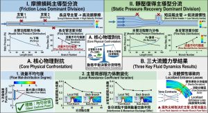
當高壓流體在主管中流動並部分進入支管時,流體經歷了動量與壓力的複雜重新分配。根據白努利定律(Bernoulli’s principle),隨著部分流體離開主管進入支管,主管內剩餘流體的軸向速度將逐漸降低。這種流速的減緩會導致動壓轉換為靜壓,產生所謂的「壓力恢復(Pressure Recovery)」現象15。因此,在分流 T 型接頭的主管端,經常可觀察到壓力不降反升的情況,這與單純的摩擦壓力降趨勢完全相反。 When high-pressure fluid flows in the header and partially enters the branch pipe, the fluid undergoes a complex redistribution of momentum and pressure. According to Bernoulli’s principle, as part of the fluid leaves the header and enters the branch, the axial velocity of the remaining fluid in the header will gradually decrease. This deceleration of flow velocity causes dynamic pressure to convert into static pressure, producing the so-called “pressure recovery” phenomenon15. Therefore, at the header end of a dividing T-junction, it is common to observe pressure rising rather than falling, which completely contradicts the trend of simple frictional pressure drops.
3.2 支管入口之壓力損失係數(Loss Coefficient) / 3.2 Pressure Loss Coefficient at the Branch Inlet
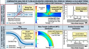
相對地,進入支管的流體則面臨急遽的幾何轉向與流線收縮。流體必須克服極大的壓力損失係數(Pressure Loss Coefficient, K)。支管路徑的阻力係數取決於分支的角度、邊緣的銳利度以及流動比率。對於直角(90°)且未經倒角處理的銳利 T 型接頭,其進入支管的流線會產生嚴重的「收縮流(Vena Contracta)」效應,並在支管入口的內側產生大規模的流場分離區16。流場的劇烈擾動不僅帶來巨觀的能量損耗,更是觸發後續局部腐蝕的流體動力學溫床。 Conversely, the fluid entering the branch pipe faces abrupt geometric redirection and streamline contraction. The fluid must overcome an extremely large Pressure Loss Coefficient (K). The resistance coefficient of the branch path depends on the branch angle, edge sharpness, and flow ratio. For a right-angle (90°) and sharp T-junction without chamfering, the streamlines entering the branch will produce a severe “vena contracta” effect, creating a large-scale flow separation zone on the inner side of the branch inlet16. The violent disturbance of the flow field not only brings macroscopic energy loss but also serves as a fluid dynamic hotbed that triggers subsequent localized corrosion.
表 1. 主管至支管分流之宏觀流場特徵與阻力對比 Table 1. Comparison of Macroscopic Flow Characteristics and Resistance for Header-to-Branch Diverging Flow15
| 分流形式 / Configuration | 流動路徑 / Flow Path | 流場分離特徵 / Flow Separation Characteristics | 壓力損失係數 (K) 估值 / Estimated Pressure Loss Coefficient (K) | 對管壁紊流之影響 / Impact on Wall Turbulence |
| 銳角 T 型接頭 / Sharp T-Junction | 主管至支管 (Branch) / Header to Branch | 支管內側產生強烈收縮流與分離泡 / Strong vena contracta and separation bubble on branch inner side | 較高 (依流量比可達 1.0~2.0) / High (1.0~2.0 depending on flow ratio) | 局部區域紊流動能與壁面剪應力極高 / Extremely high local turbulent kinetic energy and wall shear stress |
| 銳角 T 型接頭 / Sharp T-Junction | 主管至主管下游 (Run) / Header to Run Downstream | 邊界層輕微擾動,流速減緩 / Slight boundary layer disturbance, velocity reduction | 較低 (約 0.06 左右) / Low (around 0.06) | 動壓轉靜壓,壁面剪應力下降 / Dynamic pressure converts to static, wall shear stress drops |
| 冷作彎管/Y型接頭 / Cold-Bent Pipe/Y-Junction | 主管平滑轉向支管 / Smooth transition from header to branch | 二次流發展,無明顯尖銳分離泡 / Secondary flow development, no sharp separation bubbles | 中等 / Moderate | 紊流分佈較廣泛均勻,集中於彎管外側 / Turbulence distribution more widespread and uniform, concentrated on bend outer side |
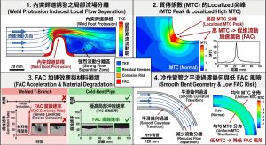
四、 「內突銲道」誘發之局部流場分離與 FAC 加速效應 / 4. Local Flow Separation and FAC Acceleration Effects Induced by “Internal Weld Protrusions”
在管線系統從主管以 T 型接頭或直接岔出支管時,銲接接合處往往難以達到完美的內部平整。即便遵循嚴格的施工規範,例如 API 560 或 ASME 規範限制內部銲道突出量(Internal Weld Protrusion)不得超過 1.6 mm(約 1/16 英吋)20,這微小的幾何突起在高速、高密度流體中仍扮演著關鍵的流場擾動源。 When a piping system branches out from a header using a T-junction or a direct branch, the welded joint often struggles to achieve perfect internal flatness. Even when strictly following construction codes, such as API 560 or ASME codes limiting internal weld protrusions to no more than 1.6 mm (about 1/16 inch)20, this minute geometric protrusion still plays a key role as a flow disturbance source in high-speed, high-density fluids.
4.1 微型彎頭效應與邊界層分離(Boundary Layer Detachment) / 4.1 Miniature Elbow Effect and Boundary Layer Detachment
當支管的高壓水或濕蒸汽流經入口處的內突銲道時,流體被迫改變原本貼壁平順的流線。這道幾何突起物在流體動力學上如同一個「微型彎頭(Miniature Elbow)」23,造成嚴重的入口效應(Entrance Effect)。流體在越過銲道頂點的瞬間,因慣性無法貼合管壁,隨即發生邊界層分離,並在銲道下游形成一個具有強烈回流與低壓渦漩的尾流分離區(Wake Separation Region)14。 When high-pressure water or wet steam in the branch pipe flows past the internal weld protrusion at the inlet, the fluid is forced to alter its originally smooth, wall-attached streamline. This geometric protrusion acts as a “miniature elbow” in fluid dynamics23, causing a severe entrance effect. The moment the fluid crosses the apex of the weld protrusion, inertia prevents it from adhering to the pipe wall, resulting in immediate boundary layer detachment and the formation of a wake separation region with strong recirculation and low-pressure vortices downstream of the weld14.
利用計算流體力學(CFD)搭配 SST k-ω等高階紊流模型進行模擬,可清晰描繪出流場在越過突起物後,會在下游一段距離處產生「流線重新附著(Flow Reattachment)」現象14。再附著長度(Reattachment Length)通常取決於銲道高度與雷諾數。在分離區內部,流體速度相對較低,看似平靜;然而,在流體重新撞擊管壁的「再附著點」及其緊鄰區域,紊流動能與壁面剪應力(Wall Shear Stress)均呈現跳躍式的極值分佈25。 Utilizing Computational Fluid Dynamics (CFD) combined with high-order turbulence models like SST k-ω, simulations clearly depict that after the fluid crosses the protrusion, a “flow reattachment” phenomenon occurs at a certain distance downstream14. The reattachment length generally depends on the weld protrusion height and Reynolds number. Inside the separation zone, the fluid velocity is relatively low and seemingly calm; however, at the “reattachment point” where the fluid re-impacts the pipe wall and its immediate vicinity, both turbulent kinetic energy and Wall Shear Stress exhibit jumping peak distributions25.
4.2 下游入口效應與極端質傳刷新 / 4.2 Downstream Entrance Effect and Extreme Mass Transfer Refresh
熱流學的深度洞察顯示,這種由銲道誘發的流場擾動,為流動加速腐蝕創造了完美的質量傳遞條件。在再附著區,極高的壁面剪應力與強烈的渦漩攪拌,會無情地削減黏滯次層厚度。由於此處主流區的流體是剛從主管進入的新鮮流體,其攜帶的金屬離子濃度遠低於溶解度極限;強大的紊流混合效應猶如一台高效率的抽水機,迅速將管壁表面溶出的鐵離子帶入主流區11。 Deep thermohydraulic insights reveal that this flow disturbance induced by the weld protrusion creates perfect mass transfer conditions for flow-accelerated corrosion. In the reattachment zone, the extremely high wall shear stress and strong vortex mixing ruthlessly thin the viscous sublayer. Since the fluid in the mainstream here is fresh fluid that just entered from the header, the concentration of metal ions it carries is far below the solubility limit; the powerful turbulent mixing acts like a highly efficient pump, rapidly sweeping the iron ions dissolved from the pipe wall surface into the mainstream11.
這種大容量的溶劑交換極大地提高了局部的質傳係數 km,導致保護性磁鐵礦層的溶解速率遠大於其生長速率,從而無法有效維持覆蓋。為求化學平衡,底層碳鋼被迫不斷釋放鐵離子(陽極溶解),進而大幅加速局部金屬流失6。 This large-capacity solvent exchange immensely increases the local mass transfer coefficient km, causing the dissolution rate of the protective magnetite layer to far exceed its growth rate, thereby failing to maintain effective coverage. To achieve chemical equilibrium, the underlying carbon steel is forced to continuously release iron ions (anodic dissolution), which vastly accelerates local metal loss6.
值得注意的是一個極具諷刺意味的材料工程現象:銲道本身通常採用合金成分較高的銲材(如含有微量鎳或較高鉻含量的填充金屬),因此具備卓越的抗 FAC 能力,幾乎不會發生明顯減薄;然而,緊鄰銲道下游的管線母材(通常鉻含量極低,如 A106 Gr.B 碳鋼),卻因為承受了銲道誘發的極端紊流,成為 FAC 的重災區,形成所謂的「銲道突起完好,下游母材破裂」之奇特失效樣態8。 It is worth noting a highly ironic materials engineering phenomenon: the weld bead itself is usually made of filler metal with higher alloy content (such as trace nickel or higher chromium content), thus possessing excellent FAC resistance and rarely experiencing significant thinning; however, the parent material immediately downstream of the weld (usually very low in chromium, such as A106 Gr.B carbon steel) becomes an FAC disaster zone because it endures the extreme turbulence induced by the weld, resulting in a peculiar failure pattern where “the weld protrusion is intact, but the downstream parent material ruptures”8.
4.3 微觀伽凡尼效應與失效形態學特徵 / 4.3 Micro-Galvanic Effects and Failure Morphological Characteristics
除了純粹的流體動力學效應外,若銲道金屬與母材金屬之間的電位存在差異(例如銲材為較高貴金屬),在具有導電性的高溫水環境中,兩者耦合會形成微觀的巨電池(Macro-cell)電流。這種伽凡尼腐蝕(Galvanic Corrosion)機制會進一步將相鄰的低電位母材作為陽極,加速其溶解速率25。研究指出,在這種耦合條件下,即便某些區域的質傳速率未達極值,宏觀電池電流亦能主導 FAC 的蔓延與惡化12。 Beyond purely fluid dynamic effects, if a potential difference exists between the weld metal and the parent metal (e.g., the weld metal is a more noble metal), coupling the two in a conductive high-temperature water environment will form a macro-cell current. This galvanic corrosion mechanism further acts on the adjacent lower-potential parent material as the anode, accelerating its dissolution rate25. Research indicates that under such coupling conditions, even if the mass transfer rate in some areas does not reach peak values, macro-cell currents can still dominate the propagation and deterioration of FAC12.
在微觀形態學上,遭受內突銲道下游流場侵蝕的管壁表面,會呈現出高度重疊的「馬蹄形沖蝕坑(Horseshoe Pits)」或「扇貝狀(Scallops)」,業界俗稱橘皮組織(Orange Peel Appearance)24。這些扇貝形凹坑的開口方向清晰地指出了局部渦漩的流動方向。此外,若該部位同時承受系統的震動疲勞或熱應力,局部的嚴重減薄極易在銲接熱影響區(HAZ)或融合線周圍誘發沿晶裂紋(Inter-granular cracks),最終導致高壓管線在毫無預警的情況下瞬間撕裂破管12。 In terms of micro-morphology, the pipe wall surface suffering from flow field erosion downstream of the internal weld protrusion will exhibit highly overlapping “horseshoe pits” or “scallops,” commonly known in the industry as an orange peel appearance24. The opening direction of these scalloped pits clearly indicates the flow direction of local vortices. Furthermore, if this section simultaneously endures vibrational fatigue or thermal stress from the system, severe local thinning can easily induce inter-granular cracks around the Heat-Affected Zone (HAZ) or fusion line, ultimately causing the high-pressure pipeline to tear and rupture instantly without warning12.
五、 「冷作彎管」之流場結構與熱機-微觀電化學協同降解 / 5. Flow Field Structure and Thermo-Mechanical-Micro-Electrochemical Synergistic Degradation in “Cold-Bent Pipes”
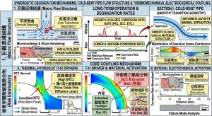
為避免 T 型接頭或直角銲接帶來的極端幾何突變與繁瑣的銲道無損檢驗,工程設計上經常將支管入口過渡段或後續轉向段改採「冷作彎管(Cold-Bent Pipe)」。冷作加工是透過機械設備在常溫下強制使鋼管產生塑性變形以改變流向。然而,深度的工程分析指出,冷作彎管在消除了「微觀銲道突出物」的同時,卻引入了複雜的宏觀二次流場,以及管壁內部深層的熱機械(Thermo-Mechanical)與微觀組織變異。To avoid the extreme geometric mutations and cumbersome non-destructive testing of welds associated with T-junctions or right-angle branch welds, engineering designs often replace the branch inlet transition section or subsequent turning sections with “Cold-Bent Pipes.” Cold working forces the steel pipe to plastically deform at room temperature using mechanical equipment to change flow direction. However, deep engineering analyses point out that while cold-bent pipes eliminate “microscopic weld protrusions,” they introduce a complex macroscopic secondary flow field, along with deep thermo-mechanical and microstructural variations inside the pipe wall.
5.1 迪恩渦流(Dean Vortices)與流場動能外移 / 5.1 Dean Vortices and the Outward Shift of Flow Kinetic Energy
當流體由主管轉向進入彎管區域時,慣性使得流體分子傾向保持直線前進,從而受到強大的離心力(Centrifugal Force)作用。這種離心力與管內彎曲造成的徑向逆壓梯度相互抗衡,導致主流區的高速核心流體被強力推向彎管的外壁側(Extrados)。同時,靠近上下管壁的低速流體則沿著管壁向彎管內側(Intrados)回流。這種複雜的三維流動現象形成了一對反向旋轉的二次流渦漩,即流體力學中著名的「迪恩渦流(Dean Vortices)」28。 When fluid turns from the header into the bend region, inertia makes fluid molecules tend to maintain a straight path, thereby subjecting them to a strong centrifugal force. This centrifugal force counters the radial adverse pressure gradient caused by the internal curvature, forcing the high-speed core fluid in the mainstream heavily toward the outer wall (extrados) of the bend. Simultaneously, the low-speed fluid near the upper and lower pipe walls flows back toward the inner wall (intrados) along the pipe wall. This complex three-dimensional flow phenomenon forms a pair of counter-rotating secondary flow vortices, famous in fluid mechanics as “Dean Vortices”28.
迪恩渦流的存在徹底顛覆了直管中的軸對稱流速分佈。CFD 研究證實,隨著流體進入 90 度彎管,最大軸向流速、最高的紊流動能與極端的壁面剪應力不再位於管線中心,而是全面集中在彎管外壁區域32。更甚者,若流體為汽水兩相流或含有微小固體雜質,根據 CFD-DEM(離散元素法)模擬分析,大質量的顆粒或液滴在離心力驅使下,無法跟隨流線轉向,會直接高速撞擊彎管外壁,導致該區域面臨嚴酷的純物理磨粒侵蝕(Erosion Rate),進一步加速保護膜的剝離13。 The presence of Dean vortices completely subverts the axisymmetric velocity distribution found in straight pipes. CFD research confirms that as fluid enters a 90-degree bend, the maximum axial velocity, highest turbulent kinetic energy, and extreme wall shear stresses are no longer located in the pipe center, but are comprehensively concentrated in the bend’s outer wall region32. Furthermore, if the fluid is a two-phase steam-water flow or contains minute solid impurities, CFD-DEM (Discrete Element Method) simulations show that massive particles or droplets, driven by centrifugal force, cannot follow the turning streamlines and will impact the outer wall of the bend directly at high speeds. This subjects the area to severe purely physical erosion rates, further accelerating the spalling of the protective film13.
5.2 塑性變形與物理壁厚減薄(Wall Thinning Ratio) / 5.2 Plastic Deformation and Physical Wall Thinning Ratio
從固體力學的視角審視,冷作彎管的成型過程本質上是一次破壞性的幾何重塑。在塑性變形期間,中性軸向外推,導致彎管外壁(Extrados)處於極強烈的拉伸應變(Tension Strain)狀態,必然發生物理性的壁厚減薄;相對地,彎管內壁(Intrados)則處於壓縮應變,發生壁厚增厚34。 Examined from a solid mechanics perspective, the forming process of a cold-bent pipe is fundamentally a destructive geometric reshaping. During plastic deformation, the neutral axis shifts outward, placing the bend’s outer wall (extrados) in a state of extremely strong tensile strain, which inevitably causes physical wall thinning; conversely, the inner wall (intrados) is in compressive strain and experiences wall thickening34.
根據 ASME B31.3 工法管線規範計算,彎管後的最薄厚度必須大於維持設計壓力的最小要求厚度 tm=(PD)/(2SE-1.2P)34。業界實務量測數據揭示了令人警醒的事實:對於曲率半徑為 3D(即彎曲半徑為管外徑的三倍)的冷作彎管,其外壁的初始減薄率通常高達 15% 至 18%;即便是 5D 彎管,其減薄率亦達 12.5%34。這意味著,在流體還未開始產生任何化學腐蝕之前,彎管外壁的承壓安全裕度已經先天性地大幅削減。 According to the ASME B31.3 process piping code calculations, the thinnest thickness after bending must be greater than the minimum required thickness to maintain design pressure, tm=(PD)/(2SE-1.2P)34. Industry practical measurement data reveals a sobering fact: for cold-bent pipes with a bend radius of 3D (i.e., bend radius is three times the pipe’s outer diameter), the initial thinning rate of the outer wall is typically as high as 15% to 18%; even for 5D bends, the thinning rate reaches 12.5%34. This implies that before the fluid even begins to generate any chemical corrosion, the pressure-bearing safety margin of the bend’s outer wall has already been substantially reduced congenitally.
5.3 殘餘應力分佈與量測技術之突破 / 5.3 Residual Stress Distribution and Breakthroughs in Measurement Technologies
冷作加工不僅改變了外部幾何,更在材料內部留下了無法輕易消除的高強度殘餘應力(Residual Stress)。傳統上利用鋸切法量測殘餘應力,常因震動與切割熱導致應力重新分佈而失準;現代研究採用放電加工(EDM)技術精確解析薄壁鋼管的應力場,發現冷作彎管外表面會殘留極巨大的拉伸殘餘應力,其數值可高達材料降伏強度的 25% 至 70%35。 Cold working not only alters external geometry but also leaves behind high-intensity residual stresses inside the material that cannot be easily eliminated. Traditionally, using saw-cutting methods to measure residual stress often proved inaccurate due to stress redistribution caused by vibration and cutting heat; modern research employing Electrical Discharge Machining (EDM) techniques to precisely resolve the stress field of thin-walled steel pipes found that enormous tensile residual stresses remain on the outer surface of cold-bent pipes, with values reaching up to 25% to 70% of the material’s yield strength35.
拉伸殘餘應力不僅是應力腐蝕破裂(SCC)與疲勞失效的催化劑,更會顯著提升應力強度因子(Stress Intensity Factor, KI),使氧化膜更容易產生微觀破裂,讓底層活性金屬暴露於腐蝕性流體中37。 Tensile residual stress is not only a catalyst for Stress Corrosion Cracking (SCC) and fatigue failure, but it also significantly elevates the Stress Intensity Factor (KI), making the oxide film more prone to micro-cracking and exposing the underlying active metal to corrosive fluids37.
5.4 應變硬化與微觀伽凡尼腐蝕(Micro-Galvanic Corrosion)之協同作用 / 5.4 Synergistic Effects of Strain Hardening and Micro-Galvanic Corrosion
在此,我們必須提出一個深度的第三階學術洞察:冷作彎管外壁的快速降解,不僅僅是宏觀的流體沖刷與殘餘應力疊加,更是金屬微觀組織電化學特性異變的必然結果。Here, we must introduce a profound third-order academic insight: the rapid degradation of a cold-bent pipe’s outer wall is not merely the superposition of macroscopic fluid erosion and residual stresses, but rather the inevitable consequence of alterations in the metal’s microstructural electrochemical properties.
冷彎造成的劇烈塑性變形會引發材料的應變硬化(Strain Hardening)與加工硬化(Work Hardening)。這在金屬晶體學中表現為差排密度(Dislocation Density)呈幾何級數增加,以及可能誘發的局部相變(例如部分奧氏體轉變為應變誘發麻田散鐵)38。研究指出,在碳鋼、雙相鋼或沃斯田鐵系不銹鋼中,由於變形程度的不均勻,高密度差排區域或新生成的麻田散鐵(Martensite)相對於周圍未嚴重變形的肥粒鐵(Ferrite)基體,會產生高達 15 mV 至 30 mV 的電位差(Potential Difference)40。 The severe plastic deformation caused by cold bending triggers strain hardening and work hardening of the material. In metal crystallography, this manifests as an exponential increase in dislocation density, along with potentially induced local phase transformations (e.g., partial austenite transforming into strain-induced martensite)38. Research indicates that in carbon steel, duplex steel, or austenitic stainless steel, due to uneven deformation, regions with high dislocation densities or newly formed martensite phases generate potential differences of up to 15 mV to 30 mV relative to the surrounding, less severely deformed ferrite matrix40.
電位較正(Noble)的麻田散鐵或高應力區扮演微觀陰極,而電位較負(Active)的肥粒鐵則被迫成為微觀陽極。這種在同一塊金屬表面形成的無數個「微觀伽凡尼電池(Micro-Galvanic Cells)」,會強烈促進陽極區的局部溶解速率40。實驗證實,隨著冷作變形率的上升(例如達到 50% 或 80% 壓下率),材料表面的點蝕(Pitting)傾向與腐蝕微孔密度會隨之急遽惡化38。 The more noble martensite or high-stress zones act as micro-cathodes, while the more active ferrite is forced to become the micro-anode. These countless “micro-galvanic cells” formed on the same metal surface strongly promote the local dissolution rate of the anodic areas40. Experiments confirm that as the cold working deformation rate rises (e.g., reaching 50% or 80% reduction), the pitting tendency and corrosion micropore density on the material surface rapidly deteriorate38.
因此,冷作彎管外壁形成了一個熱力學、微觀電化學與流體力學的「完美風暴」區:迪恩渦流不斷以高剪切力刷新質傳邊界層(物理剝離)、拉伸殘餘應力撕裂保護膜(力學破壞)、微觀伽凡尼效應持續驅動局部陽極溶解(電化學腐蝕),最終導致該區域呈現大面積的快速均勻減薄與點蝕叢生。Therefore, the outer wall of a cold-bent pipe forms a “perfect storm” zone of thermodynamics, micro-electrochemistry, and fluid dynamics: Dean vortices constantly refresh the mass transfer boundary layer with high shear forces (physical spalling), tensile residual stresses tear the protective film (mechanical destruction), and micro-galvanic effects continuously drive local anodic dissolution (electrochemical corrosion). This ultimately causes the area to exhibit large-scale, rapid uniform thinning accompanied by clusters of pitting.
六、 「內突銲道」與「冷作彎管」降解行為之綜合對比分析 / 6. Comprehensive Comparative Analysis of Degradation Behaviors for “Internal Weld Protrusions” and “Cold-Bent Pipes”
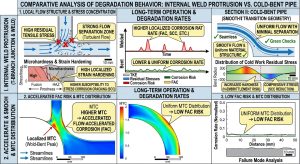
透過前述機制分析,我們可深刻理解「內突銲道」與「冷作彎管」在引發局部管壁減薄現象時,其本質動力來源與空間分佈有著系統性的差異。Through the aforementioned mechanistic analyses, we can profoundly understand that “internal weld protrusions” and “cold-bent pipes” exhibit systematic differences in their fundamental driving sources and spatial distributions when triggering localized pipe wall thinning phenomena.
對於內突銲道,其失效機制純粹受控於空間水動力學(Spatial Hydrodynamics)的局部擾動。即流場剝離與重新附著的準確位置,決定了腐蝕發生的確切坐標。此處的鋼材母材微觀組織並未受到機械破壞,材料整體的電化學活性並無顯著提升;破壞的成因,完全是外部流體因幾何突變而產生的極端質傳速率,「強行」剝奪了磁鐵礦保護層。這是一種由外而內的單向侵蝕。For internal weld protrusions, the failure mechanism is purely governed by local disturbances in spatial hydrodynamics. That is, the exact coordinates of corrosion occurrence are determined by the precise locations of flow separation and reattachment. The microstructure of the parent steel here has not suffered mechanical destruction, and the overall electrochemical activity of the material has not significantly increased; the cause of destruction is entirely the extreme mass transfer rates generated by external fluids due to geometric mutations, which “forcibly” strip away the magnetite protective layer. This is a one-way erosion from the outside in.
相反地,對於冷作彎管,其失效機制則是多重物理量協同與體積性(Synergistic and Volumetric)的內外夾擊。冷彎加工無意間在同一空間位置(外壁)堆疊了致命的劣勢:製造過程的物理壁厚最薄、迪恩渦流導致的水動力沖刷最強、拉伸殘餘應力最大、以及差排堆積導致的金屬溶解電位最活躍。這是一種從材料內部晶格缺陷到外部流場特徵共同促成的複合式降解。這解釋了為何許多電廠高壓蒸汽管線的彎頭外側會在無預警的情況下發生大面積的爆管,因為它不僅僅是流體的物理削弱,更是材料自身抗性機制的內在瓦解。Conversely, for cold-bent pipes, the failure mechanism is an internal and external pincer attack characterized by synergistic and volumetric effects of multiple physical quantities. Cold bending inadvertently stacks fatal disadvantages at the same spatial location (outer wall): the thinnest physical wall thickness from manufacturing, the strongest hydrodynamic erosion caused by Dean vortices, the largest tensile residual stress, and the most active metal dissolution potentials resulting from dislocation pile-ups. This is a composite degradation driven jointly by internal lattice defects and external flow field features. This explains why the outer bends of high-pressure steam pipelines in many power plants experience massive blowouts without warning, as it is not merely a physical weakening by fluid, but an inherent collapse of the material’s own resistance mechanisms.
表 2. 內突銲道與冷作彎管之流場紊流與材料複合降解特性對比Table 2. Comparison of Flow Turbulence and Material Composite Degradation Characteristics Between Internal Weld Protrusions and Cold-Bent Pipes
| 比較參數 / Comparison Parameter | 內突銲道(支管 T 型銲接接頭) / Internal Weld Protrusion (Branch T-Junction Weld) | 冷作彎管(主管轉向支管過渡) / Cold-Bent Pipe (Header to Branch Transition) |
| 流場擾動特徵 / Flow Disturbance Features | 流場幾何分離、尾流分離泡、下游流線重新附著 / Geometric flow separation, wake separation bubbles, downstream streamline reattachment | 迪恩渦流 (Dean Vortices) 二次流發展、離心力作用導致流速外偏 / Dean Vortices secondary flow development, centrifugal force pushing velocity outward |
| 最高壁面剪應力位置 / Location of Max Wall Shear Stress | 銲道下游數倍管徑處(再附著區)極為局部 / Extremely localized at a few pipe diameters downstream of the weld (reattachment zone) | 彎管外壁(Extrados)全面弧形區域 / The entire curved area of the outer wall (extrados) |
| 初始壁厚物理狀態 / Initial Physical Wall Thickness State | 母材壁厚均勻(僅受銲接熱影響,無機械減薄) / Uniform parent wall thickness (only affected by weld heat, no mechanical thinning) | 外壁受拉伸先天減薄(高達15-18%),內壁壓縮增厚 / Congenital thinning of outer wall due to tension (up to 15-18%), inner wall thickened by compression |
| 材料應力與微觀狀態 / Material Stress and Micro-State | 銲接熱應力集中、熱影響區(HAZ)沿晶裂紋風險 / Weld thermal stress concentration, inter-granular crack risk in Heat-Affected Zone (HAZ) | 巨觀拉伸殘餘應力、高密度差排、變形誘發相變(微觀伽凡尼效應) / Macroscopic tensile residual stress, high dislocation density, deformation-induced phase transformation (micro-galvanic effects) |
| 主導降解機制 / Dominant Degradation Mechanism | 純流體動力學驅動之局部質傳係數突增(單純 FAC) / Local mass transfer coefficient surge purely driven by fluid dynamics (simple FAC) | 流體沖刷、殘餘應力與熱機-電化學活化之協同降解(FAC + E-C + SCC) / Synergistic degradation of fluid erosion, residual stress, and thermo-mechanical-electrochemical activation (FAC + E-C + SCC) |
| 表面損耗形態特徵 / Surface Loss Morphological Features | 橘皮組織、高度重疊之馬蹄形沖蝕坑(Scallops)、局部深溝 / Orange peel appearance, highly overlapping horseshoe pits (scallops), localized deep grooves | 大面積平滑之均勻減薄、伴隨微裂紋或高密度點蝕坑 / Large-area smooth uniform thinning, accompanied by micro-cracks or high-density pitting |
| 檢測難度與風險特性 / Inspection Difficulty and Risk Features | 減薄區域極端局部且隱蔽,超音波單點量測極易遺漏 / Thinned areas are extremely localized and concealed, easily missed by ultrasonic single-point measurement | 減薄面積廣闊,破裂前承受壓力裕度極低,易發生災難性大面積爆管 / Widespread thinned areas, extremely low pressure margin before rupture, prone to catastrophic large-area blowouts |
七、 複循環發電廠高壓系統之防護策略與工程實務 / 7. Protection Strategies and Engineering Practices for High-Pressure Systems in CCPP
理解了「內突銲道」與「冷作彎管」各自誘發管壁減薄的機制後,複循環發電廠(CCPP)可針對性地在設計、製造施工與營運維護階段,採取不同的防護與監測策略,以確保高壓管線系統的長期壽命與安全性。Having understood the mechanisms by which “internal weld protrusions” and “cold-bent pipes” induce pipe wall thinning, Combined Cycle Power Plants (CCPP) can adopt targeted protection and monitoring strategies during design, manufacturing, construction, and operation/maintenance phases to ensure the long-term lifespan and safety of high-pressure piping systems.
7.1 材料選擇與合金成分設計 / 7.1 Material Selection and Alloy Composition Design
在管線設計初期,冶金成分的升級是抵抗 FAC 與 E-C 的最有效、也是最基礎的防線。對於 HRSG 中極易受 FAC 影響的高壓省煤器(HP Economizer)、預熱器與低壓蒸發器管線1,應盡量避免使用抗腐蝕能力貧弱的純碳鋼(如 ASTM A106 Gr.B)。研究顯示,鋼材中微量的鉻(Cr)、鉬(Mo)與銅(Cu)即可顯著提升材料對 FAC 的抵抗力。 In the initial stages of piping design, upgrading metallurgical composition is the most effective and fundamental defense against FAC and E-C. For pipelines in HRSG highly susceptible to FAC, such as High-Pressure (HP) economizers, preheaters, and low-pressure evaporators1, pure carbon steel with poor corrosion resistance (like ASTM A106 Gr.B) should be avoided as much as possible. Research shows that trace amounts of Chromium (Cr), Molybdenum (Mo), and Copper (Cu) in steel can significantly enhance the material’s resistance to FAC.
依據實證數據,當碳鋼中的鉻含量當量超過 0.1% 時,FAC 速率會出現急遽下降的轉折點;若升級使用含有 1.25% 鉻的低合金鋼(如 P11/T11)、2.25% 鉻的鋼材(如 P22/T22),甚至高達 9% 鉻的馬氏體耐熱鋼(如 P91),則 FAC 的威脅幾可完全消除5。高鉻合金不僅能有效抵抗因銲道質傳突增引起的快速溶解,其生成的極緻密含鉻尖晶石氧化層結構,也能強大抵禦冷作彎管外壁因微觀伽凡尼效應所引發的電化學腐蝕。 Based on empirical data, when the chromium content equivalent in carbon steel exceeds 0.1%, the FAC rate exhibits a sharp declining turning point; if upgraded to low-alloy steel containing 1.25% chromium (e.g., P11/T11), 2.25% chromium steel (e.g., P22/T22), or even martensitic heat-resistant steel with up to 9% chromium (e.g., P91), the threat of FAC can be virtually eliminated5. High-chromium alloys not only effectively resist rapid dissolution caused by mass transfer surges at welds, but their highly dense chromium-containing spinel oxide layer structures can also robustly defend against electrochemical corrosion triggered by micro-galvanic effects on the outer walls of cold-bent pipes.
7.2 銲接工法與彎管加工之嚴格控制 / 7.2 Strict Control of Welding Procedures and Pipe Bending Fabrication
針對 T 型接頭與直角分支銲接,必須嚴格控制根部銲道的成型品質。施工單位應強制規範管內壁的突起量必須小於 1.6 mm,甚至追求與母材齊平。為了達到此一標準,建議根部打底銲道全面採用鎢極氣體保護銲(GTAW,即氬銲),以獲得極為平滑的內部過渡,最大程度地減少邊界層分離所產生的紊流動能與尾流泡45。 For T-junctions and right-angle branch welding, the forming quality of the root weld bead must be strictly controlled. Construction entities should enforce specifications mandating that the inner pipe wall protrusion must be less than 1.6 mm, or even strive for flushness with the parent material. To achieve this standard, it is recommended to entirely use Gas Tungsten Arc Welding (GTAW, or Argon welding) for the root pass to obtain an extremely smooth internal transition, maximally minimizing turbulent kinetic energy and wake bubbles generated by boundary layer separation45.
針對冷作彎管,為了先天抵消製造過程中的物理減薄(例如 3D 彎管高達 18% 的減薄量),工程設計必須在彎管加工前,選用具有足夠厚度補償(Thickness Allowance)的加厚母管(如 Schedule 80 或 Schedule 160 管材)作為原料34。更關鍵的防護程序在於,冷作彎曲加工完成後,必須對彎管實施適當的後熱處理(Post-Weld Heat Treatment, PWHT 或高溫應力消除退火)。退火處理不僅能大幅釋放外壁高達降伏強度 70% 的拉伸殘餘應力,更能促使材料微觀組織的再結晶或回復,消除由高差排密度引起的微觀伽凡尼電池效應,從根本上恢復材料的耐蝕能力46。 For cold-bent pipes, to congenitally offset physical thinning during manufacturing (e.g., up to 18% thinning in 3D bends), engineering designs must utilize thickened mother pipes with sufficient Thickness Allowance (such as Schedule 80 or Schedule 160 pipes) as raw materials prior to bending34. An even more critical protective procedure is that after cold bending is completed, the bent pipe must undergo appropriate Post-Weld Heat Treatment (PWHT) or high-temperature stress relief annealing. Annealing not only substantially releases tensile residual stresses that reach up to 70% of the yield strength on the outer wall, but also promotes recrystallization or recovery of the material’s microstructure, eliminating the micro-galvanic cell effects caused by high dislocation densities, thereby fundamentally restoring the material’s corrosion resistance46.
7.3 水化學控制(Water Chemistry Control) / 7.3 Water Chemistry Control
在電廠的日常營運層面,透過水化學調控是抑制管線降解的全域性關鍵。維持適當的弱鹼性水環境,將給水 pH 值嚴格控制在 9.2 至 9.8 之間,能有效降低磁鐵礦的熱力學溶解度極限,從根本上減緩 FAC 的擴散驅動力4。此外,對於全揮發性處理(AVT)系統,適量控制溶氧量,或使用高效的胺類鹼化劑如乙醇胺(Ethanolamine, ETA)替代傳統的氨水,不僅能優化氣液兩相分配比,更能使金屬表面的氧化膜生長得更為緻密,大幅提升 A106 Gr.B 等碳鋼抵抗流體沖刷的能力6。 At the daily operational level of power plants, water chemistry control is a global key to suppressing pipeline degradation. Maintaining an appropriately weakly alkaline water environment, strictly controlling feedwater pH between 9.2 and 9.8, can effectively lower the thermodynamic solubility limit of magnetite and fundamentally slow the diffusion driving force of FAC4. Furthermore, for All-Volatile Treatment (AVT) systems, properly controlling dissolved oxygen or using high-efficiency amine alkalizing agents like Ethanolamine (ETA) to replace traditional aqueous ammonia can not only optimize gas-liquid phase partitioning but also make the oxide film grow much denser on the metal surface, substantially enhancing the resistance of carbon steels like A106 Gr.B against fluid erosion6.
7.4 現代非破壞性檢測(NDT)技術之應用 / 7.4 Application of Modern Non-Destructive Testing (NDT) Technologies
在定期維護與大修檢查方面,由於內突銲道的 FAC 減薄區極度局部化且深藏於下游的再附著點,傳統的超音波單點測厚(UT)猶如瞎子摸象,極易產生量測盲區並錯失最薄弱處。目前先進電廠與檢驗機構強烈推崇採用相位陣列超音波檢測(Phased Array Ultrasonic Testing, PAUT),搭配可適應管徑曲率的柔性掃描器(Flexible PA Scanner)48。 In terms of periodic maintenance and overhaul inspections, since the FAC thinning zone of an internal weld protrusion is extremely localized and hidden deep at the downstream reattachment point, traditional Ultrasonic Testing (UT) single-point thickness measurement is like the blind feeling an elephant, highly prone to measurement blind spots and missing the weakest points. Advanced power plants and inspection agencies currently highly recommend adopting Phased Array Ultrasonic Testing (PAUT), paired with Flexible PA Scanners adaptable to pipe curvatures48.
PAUT 技術能夠對銲道下游數倍管徑的入口效應區,以及冷彎管大面積的外壁弧面,進行連續且高解析度的 C-scan(平面圖)、B-scan(斷面圖)與 D-scan 整合三維成像48。這種檢測手段能夠以接近 2 mm 的近表面解析度,精準捕捉馬蹄形沖蝕坑的輪廓、微小點蝕以及殘餘壁厚的精確數值,為廠方評估管線剩餘壽命(Remaining Life Assessment)與安排預防性更換提供無可替代的科學依據。 PAUT technology can perform continuous and high-resolution integrated 3D imaging (C-scan planar, B-scan cross-sectional, and D-scan) on the entrance effect zone several pipe diameters downstream of the weld and the large-area outer curved surface of cold-bent pipes48. This inspection method, with a near-surface resolution close to 2 mm, precisely captures the contours of horseshoe pits, minute pitting, and the exact values of residual wall thickness. It provides irreplaceable scientific evidence for plant operators to evaluate Remaining Life Assessment and schedule preventative replacements.
7.5 基於 2026 版 ASME B31J 規範強制導入之工法差異與決策分析 (1.5D 銲接彎頭 vs. 3D/5D 冷作彎管) / 7.5 Methodology Differences and Decision Analysis Based on the Mandatory Implementation of 2026 ASME B31J (1.5D Welded Elbows vs. 3D/5D Cold-Bent Pipes)
針對發電廠與化工業高能管線(HEP)之設計與施工,2026 年版的 ASME B31.1 與 B31.3 規範迎來了典範轉移,正式廢除過去沿用半世紀的 Appendix D 經驗公式,全面強制導入 ASME B31J 作為管線元件應力強度因子(Stress Intensification Factor, SIF)與柔性因子(Flexibility Factor, k)之計算基準49。在此新法規框架下,傳統 1.5D 短半徑銲接彎頭與新型 3D/5D 大半徑冷作彎管在工程實務上的優劣勢出現了根本性的差異重估: For the design and construction of High Energy Piping (HEP) in power plants and chemical industries, the 2026 editions of ASME B31.1 and B31.3 codes usher in a paradigm shift. They officially abolish the Appendix D empirical formulas used for half a century, mandatorily implementing ASME B31J as the calculation baseline for piping component Stress Intensification Factors (SIF) and Flexibility Factors (k)49. Under this new regulatory framework, the practical advantages and disadvantages of traditional 1.5D short-radius welded elbows versus new 3D/5D large-radius cold-bent pipes undergo a fundamental reevaluation:
- ASME B31J 應力解耦與模型精確化: 舊版規範的 SIF 數據源於 1950 年代 Markl 的單向彎曲疲勞實驗,將複雜的三維受力狀態極度簡化,經常迫使工程師高估系統應力並設計過度保守的熱膨脹迴路50。2026 版 ASME B31J 則基於高解析度三維有限元素分析(FEA),為每一個管件構建了完全解耦的係數矩陣,包含獨立的面內(ii)、面外(io)與扭轉(it)SIF,使得局部橢圓化(Ovalization)對系統釋放能量的貢獻得被正確評估27。 ASME B31J Stress Decoupling and Model Refinement: The SIF data in the old code originated from A.R.C. Markl’s unidirectional bending fatigue experiments in the 1950s, which overly simplified complex 3D stress states and frequently forced engineers to overestimate system stresses and design overly conservative thermal expansion loops50. The 2026 edition of ASME B31J, however, is based on high-resolution 3D Finite Element Analysis (FEA), constructing a fully decoupled coefficient matrix for each pipe fitting, including independent in-plane (ii), out-of-plane (io), and torsional (it) SIFs. This allows the contribution of local ovalization to the system’s energy release to be accurately evaluated27.
- 1.5D 銲接彎頭的物理與流場劣勢: 在 1.5D 傳統銲接彎頭中,急遽的曲率轉變導致極為嚴重的橫截面橢圓化,產生高度的應力集中。更嚴峻的是,這種工法的圓周銲道剛好座落於幾何突變與應力集中的高危險熱區。在長期高溫、高壓條件下,銲道極易成為熱潛變破裂(Creep Rupture)及應力腐蝕破裂(SCC)的溫床。從流體力學視角來看,高速核心流沖入 1.5D 短彎頭時,會在內弧側(Intrados)產生強烈的逆壓梯度與大規模邊界層分離。這不僅加劇了流體加速腐蝕(FAC),其伴隨的渦流脫落(Vortex Shedding)還會誘發高頻流體誘發振動(FIV),進一步消耗管件的疲勞壽命50。 Physical and Flow Field Disadvantages of 1.5D Welded Elbows: In traditional 1.5D welded elbows, the abrupt change in curvature causes severe cross-sectional ovalization, generating high stress concentrations. More severely, the circumferential weld of this method sits exactly in the high-risk hot zone of geometric mutation and stress concentration. Under long-term high-temperature and high-pressure conditions, the weld bead is highly prone to becoming a breeding ground for Creep Rupture and Stress Corrosion Cracking (SCC). From a fluid dynamics perspective, when a high-speed core flow rushes into a 1.5D short elbow, it generates strong adverse pressure gradients and massive boundary layer separation on the intrados. This not only exacerbates Flow-Accelerated Corrosion (FAC), but the accompanying vortex shedding also induces high-frequency Fluid-Induced Vibration (FIV), further consuming the fitting’s fatigue life50.
- 3D/5D 大半徑冷作彎管之實務優勢與「能彎不銲」策略: 相對於1.5D 彎頭,3D(曲率半徑為 3 倍外徑)或 5D 冷作彎管的幾何過渡極為平緩。依據 ASME B31J 計算,其面內、面外與扭轉 SIF 皆急遽下降,幾乎趨近於理想直管的絕對下限(1.0)。這意味著 5D 彎管的力學行為已等效於直管,具有無可比擬的安全裕度。透過無縫冷作工法,工程設計得以徹底消除位於應力集中區的圓周銲道,也連帶消除了系統的流體積存死角(Dead legs)並大幅降低了非破壞性檢測(NDT)的高昂成本50。 Practical Advantages of 3D/5D Large-Radius Cold-Bent Pipes and the “Bend Instead of Weld” Strategy: Compared to 1.5D elbows, the geometric transition of 3D (bend radius equals 3 times the outer diameter) or 5D cold-bent pipes is extremely smooth. According to ASME B31J calculations, their in-plane, out-of-plane, and torsional SIFs all drop sharply, approaching the absolute lower limit for an ideal straight pipe (1.0). This means the mechanical behavior of a 5D bend is equivalent to that of a straight pipe, possessing an unparalleled safety margin. Through seamless cold working methods, engineering design can completely eliminate circumferential welds located in stress concentration zones, which in turn eliminates fluid accumulation dead legs in the system and drastically reduces the exorbitant costs of Non-Destructive Testing (NDT)50.
- 彎後熱處理(IH-PBHT)之絕對必要性: 儘管 3D/5D 冷作彎管在幾何與法規評價上具備壓倒性優勢,但冷作加工過程無可避免地會引入晶格扭曲與龐大的殘餘應力。因此,在實務工法中,必須結合感應加熱彎後熱處理(Induction Heating Post-Bend Heat Treatment, IH-PBHT)進行亞臨界退火52。此程序能徹底釋放冷彎應力,恢復材料微觀冶金組織,確保大半徑彎管的抗潛變能力與疲勞壽命真正達到或超越原廠無縫直管的法規標準。 The Absolute Necessity of Post-Bend Heat Treatment (IH-PBHT): Although 3D/5D cold-bent pipes have overwhelming advantages in geometry and regulatory evaluation, the cold working process inevitably introduces lattice distortions and massive residual stresses. Therefore, in practical procedures, Induction Heating Post-Bend Heat Treatment (IH-PBHT) must be integrated for subcritical annealing52. This process completely releases cold bending stresses, restores the material’s microstructural metallurgy, and ensures that the large-radius bend’s creep resistance and fatigue life truly meet or exceed the regulatory standards of original seamless straight pipes.
7.6 多維度利害關係人對管線實務之決策與考量 / 7.6 Multi-Dimensional Stakeholder Decisions and Considerations on Piping Practices
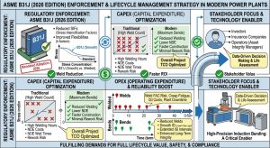
在評估發電廠高壓管線過渡段的設計時,專案的各方利害關係人針對「內突銲道(1.5D 銲接彎頭)」與「冷作彎管(3D/5D大半徑)」皆會從各自的核心職責出發,形成多維度的實務要求與營運決策:When evaluating the design of high-pressure piping transition sections in power plants, stakeholders across the project form multi-dimensional practical requirements and operational decisions regarding “internal weld protrusions (1.5D welded elbows)” and “cold-bent pipes (3D/5D large radius)” based on their core responsibilities:
- 6.1 業主對於管線銲道與冷作彎管維護管理及營運決策: 業主最關切的是生命週期營運支出(OPEX)與系統的整體可靠度。針對高溫及特定腐蝕介質環境(例如 316L 輔助蒸汽系統),若大量使用 1.5D 電銲彎頭,其銲接熱影響區(HAZ)在長期運轉下極易成為應力腐蝕破裂(SCC)的溫床。改採 3D/5D 冷作無縫彎管,能直接消除高風險區的環向銲縫,並減少流體積存的系統死角(Dead legs)51。此舉從根本上降低了長期營運中需執行的非破壞性檢測(NDT)維護頻率與潛在洩漏風險,為業主實現無死角防護並大幅提升系統可用率51。 7.6.1 Owners’ Decisions on Weld and Cold-Bent Pipe Maintenance Management and Operations: Owners are most concerned with Operational Expenditure (OPEX) over the lifecycle and overall system reliability. For high-temperature and specific corrosive media environments (such as 316L auxiliary steam systems), if 1.5D welded elbows are used extensively, their Heat-Affected Zones (HAZ) are highly susceptible to becoming breeding grounds for Stress Corrosion Cracking (SCC) during long-term operation. Adopting 3D/5D cold-bent seamless pipes directly eliminates circumferential welds in high-risk zones and reduces fluid-accumulating system dead legs51. This fundamentally reduces the frequency of NDT maintenance required during long-term operations and potential leakage risks, achieving zero-dead-spot protection for owners and vastly enhancing system availability51.
- 6.2 EPC 承包商設計單位之空間佈置與實務考量: 對 EPC(設計採購施工)統包商而言,B31J 的導入使 3D/5D 彎管的柔性特徵值得以獲得更精確的評價,其 SIF 近乎 1.0,遠低於電銲彎頭50。工程師無須為了消化舊規範下「虛假的」熱應力而盲目增加熱膨脹迴圈,從而大幅節省了三維佈置空間與管材資本支出(CAPEX)51。此外,在銲接工序上,客製化的 3D/5D 連續彎管能顯著減少系統中的對銲接頭,這不僅避免了法規對於銲縫接頭品質係數(Ej)的力學折減懲罰,更巨幅降低了射線(RT)或超音波(UT)等 NDT 檢驗密度與連帶的專案成本51。 7.6.2 EPC Contractors’ Layout and Practical Considerations: For EPC (Engineering, Procurement, and Construction) turnkey contractors, the introduction of B31J allows the flexibility characteristics of 3D/5D bends to be evaluated much more accurately, with their SIF nearing 1.0, far lower than welded elbows50. Engineers no longer need to blindly add thermal expansion loops to digest “false” thermal stresses from old codes, drastically saving 3D layout space and piping Capital Expenditure (CAPEX)51. Additionally, in welding processes, customized 3D/5D continuous bent pipes significantly reduce butt-weld joints in the system. This not only avoids the code’s mechanical reduction penalties for weld joint quality factors (Ej) but also hugely lowers the inspection density and associated project costs of NDT like RT or UT51.
- 6.3 廠務管理者對於流體力學與壓降優化之要求: 廠務端追求的是流體力學的穩定與熱力學效率。1.5D 彎頭曲率過急,易在流體轉向時引發劇烈紊流與不必要的壓降,進而加劇管壁的流體加速腐蝕(FAC)50。3D/5D 冷作彎管具備平順的內壁流道,並可依現場佈置需求客製化非標準角度(如 22.5° 或 67.5°)51。這不僅顯著降低了新廠蒸汽吹管以及日常運轉時的壓降,更確保了供給汽機軸封與除氧器等關鍵設備的流體穩定性維持在最佳狀態。 7.6.3 Plant Managers’ Requirements for Fluid Dynamics and Pressure Drop Optimization: Plant operations pursue fluid dynamic stability and thermodynamic efficiency. The overly sharp curvature of 1.5D elbows easily triggers violent turbulence and unnecessary pressure drops during fluid redirection, which exacerbates Flow-Accelerated Corrosion (FAC) on pipe walls50. 3D/5D cold-bent pipes possess smooth internal flow paths and can be customized to non-standard angles (e.g., 22.5° or 67.5°) according to site layout needs51. This significantly reduces pressure drops during new plant steam blows and daily operations, ensuring that the stability of fluid supplied to critical equipment like turbine gland seals and deaerators is maintained at optimal states.
- 6.4 冷作彎管施作協力廠商之實務要求與因應策略: 以冷作彎管施作協力廠商的角度而言,面對 ASME B31.3 與 B31.1 對於彎管成型後最小壁厚與橢圓度的嚴格要求,必須採取主動的製程管控。實務上,廠商會依據材料特性(如 A106 碳鋼或 316L 不銹鋼)與目標曲率半徑(3D 或 5D),精準計算出 10% 至 18% 不等的預期物理減薄率,從而要求工程設計端提供具有足夠厚度補償(Thickness Allowance)的加厚母管(如 Schedule 80 甚至 160)作為素材34。同時,透過精密的數控(CNC)彎管機配合內部芯棒(Mandrel)的穿心控制,廠商方能將橫截面橢圓化控制在法規容許的 8% 以內,確保成型品質。 7.6.4 Cold-Bent Pipe Subcontractors’ Practical Requirements and Response Strategies: From the perspective of cold-bent pipe subcontractors, facing the strict requirements of ASME B31.3 and B31.1 regarding minimum wall thickness and ovality post-bending, proactive process control must be adopted. In practice, subcontractors accurately calculate expected physical thinning rates ranging from 10% to 18% based on material properties (e.g., A106 carbon steel or 316L stainless steel) and target bend radii (3D or 5D). Consequently, they request engineering design to provide thickened mother pipes with sufficient Thickness Allowance (such as Schedule 80 or even 160) as raw material34. Meanwhile, by using precise Computer Numerical Control (CNC) pipe benders paired with internal mandrel controls, manufacturers can limit cross-sectional ovalization to within the code-allowed 8%, guaranteeing forming quality.
7.7 潁璋工程「能彎不銲」三合一工法之核心價值與合規落實 / 7.7 Core Value and Compliance Implementation of Ying-Zhang Engineering’s “Bend Instead of Weld” Three-in-One Methodology
為了徹底解決傳統 1.5D 銲接彎頭所衍生的應力集中、銲道劣化與紊流沖蝕問題,本研究進一步導入業界領先之「潁璋工程」實務管理核心,探討其如何將學術理論轉化為高能管線(HEP)的安全解方。To fundamentally resolve the stress concentration, weld degradation, and turbulence erosion problems derived from traditional 1.5D welded elbows, this study further introduces the industry-leading practical management core of “Ying-Zhang Engineering,” exploring how it transforms academic theories into safe solutions for High Energy Piping (HEP).
- 7.1 核心理念「能彎不銲」與三合一工法優化: 本研究強烈支持並驗證了「能彎則彎,不得不銲」(Bend where possible, weld only when necessary)的工程策略53。該理念旨在優化管線路徑設計,透過 3D/5D 冷作無縫彎管取代傳統 1.5D 電銲彎頭,徹底消除高應力區的幾何突變。為落實此理念並確保最高級別的法規合規性,導入潁璋工程(Ying-Zhang Engineering)所提倡的「三合一工法」(3D/5D CNC 大半徑冷作彎管 + IH-PBHT 單管感應亞臨界彎後熱處理 + QR Code 雲端數位履歷),是發揮大半徑優勢的唯一解方51。此工法管理的核心價值在於徹底落實「能彎不銲」的設計理念,從源頭將易受流體沖刷與疲勞破壞的銲縫轉化為連續平滑的母材彎曲段。針對高能管線,此工法的執行不僅是製造手段的升級,更是嚴格對接 ASME B31.1 與 B31J 規範的合規性展現54。此三合一工法不僅在物理流場形貌上實現了無縫過渡,更在微觀冶金與文件稽核上達到 ASME 規範的最高標準,為現代高能管線之結構完整性設計、管口負載優化及系統生命週期管理,提供了最具實務價值的解決方案。 7.7.1 Core Philosophy “Bend Instead of Weld” and Three-in-One Methodology Optimization: This study strongly supports and verifies the engineering strategy of “Bend where possible, weld only when necessary”53. This philosophy aims to optimize piping routing designs by replacing traditional 1.5D welded elbows with 3D/5D cold-worked seamless bends, completely eliminating geometric mutations in high-stress zones. To implement this philosophy and ensure the highest level of code compliance, introducing the “Three-in-One Methodology” advocated by Ying-Zhang Engineering (3D/5D CNC large-radius cold bending + IH-PBHT single-pipe induction subcritical post-bend heat treatment + QR Code cloud digital resume) is the sole solution to fully leverage the advantages of large radii51. The core value of this methodology management lies in thoroughly implementing the “bend instead of weld” design philosophy, transforming welds—which are highly susceptible to fluid erosion and fatigue failure—into continuously smooth parent material curved sections right from the source. For high-energy piping, executing this method is not just an upgrade in manufacturing means, but an exhibition of strict compliance aligned with ASME B31.1 and B31J codes54. This three-in-one methodology not only realizes seamless transitions in physical flow field morphology but also meets the highest standards of ASME codes in microstructural metallurgy and documentation auditing, providing the most practically valuable solution for the structural integrity design, nozzle load optimization, and lifecycle management of modern high-energy pipelines.
- 7.2 應變率 (5%~20%) 規範放寬與 IH-PBHT 適用之深度解析: 在 2026 版 ASME B31.1(如 Table 129.3.3.1-1 等相關章節)與 B31.3(Para 332.4.2)的規範架構下,管線冷彎成型所產生的局部塑性變形(應變率,Fiber Elongation / Strain Rate)是決定後續熱處理的關鍵極限值。當大半徑(如 5D)冷作彎管的成型應變率落在5%≤ϵ≤20% 的特定區間內時(例如,5D 彎頭的理論彎曲應變約落在 10%),法規並未全面禁止冷作,而是嚴格要求製造廠必須檢視材料類別(如 P-No.1, P-No.4, P-No.5A)與系統設計溫度,以決定是否強制啟動彎後熱處理(Post-Bend Heat Treatment, PBHT)的介入機制52。傳統觀點可能將此 5%~20% 的塑性應變視為材料劣化的隱患,然而,透過潁璋工程三合一工法中的 IH-PBHT(感應加熱彎後熱處理) 精準介入,此規範放寬區間反而成為優化管件性能的最佳契機。IH-PBHT 針對冷彎變形區實施全體積(Volumetric)的局部亞臨界退火(Subcritical Annealing)或正火加回火(Normalizing & Tempering)。這不僅徹底清除了冷作彎曲帶來的應變硬化與巨觀拉伸殘餘應力,更使材料在微觀冶金結構上等同於「重生」52。這種深度的應力釋放與晶格修復,使 5D 彎管在微觀組織上完全滿足 ASME B31 嚴苛的應變率法規要求,並最終賦予其超越傳統 1.5D 銲接彎頭的抗潛變破裂能力與抗流動加速腐蝕(FAC)效能,完美實踐了「能彎不銲」之最高工程價值50。 7.7.2 Deep Analysis of Strain Rate (5%~20%) Code Relaxation and IH-PBHT Application: Under the code framework of the 2026 edition of ASME B31.1 (such as Table 129.3.3.1-1 and related sections) and B31.3 (Para 332.4.2), the local plastic deformation (Fiber Elongation / Strain Rate) generated by cold pipe bending is a critical limit value for determining subsequent heat treatment. When the forming strain rate of large-radius (e.g., 5D) cold-bent pipes falls within the specific interval of 5%≤ϵ≤20% (for example, the theoretical bending strain of a 5D bend is approximately 10%), the code does not completely prohibit cold working; rather, it strictly requires the manufacturer to examine the material category (such as P-No.1, P-No.4, P-No.5A) and the system design temperature to determine whether to trigger the mandatory intervention mechanism of Post-Bend Heat Treatment (PBHT)52. Traditional perspectives might view this 5%~20% plastic strain as a hidden danger for material degradation; however, through the precise intervention of IH-PBHT (Induction Heating Post-Bend Heat Treatment) in Ying-Zhang Engineering’s three-in-one methodology, this relaxed code interval instead becomes the optimal opportunity to optimize fitting performance. IH-PBHT applies volumetric localized Subcritical Annealing or Normalizing & Tempering to the cold-bent deformation zone. This not only thoroughly eradicates the strain hardening and macroscopic tensile residual stresses brought by cold bending, but also renders the material equivalent to being “reborn” in terms of microstructural metallurgy52. This deep stress relief and lattice repair allow the 5D bend to fully meet the stringent strain rate code requirements of ASME B31 in microstructure, ultimately endowing it with Creep Rupture resistance and Flow-Accelerated Corrosion (FAC) efficiency that surpass traditional 1.5D welded elbows, perfectly manifesting the highest engineering value of “bend instead of weld”50.
7.8 高能管線 1°~3° 洩水坡度設計下之冷作彎管與銲接彎頭衝蝕行為差異 / 7.8 Differences in Erosion Behavior Between Cold-Bent Pipes and Welded Elbows Under 1°~3° Drainage Slope Designs for High Energy Piping
在高能管線(High Energy Piping, HEP)如蒸汽與冷凝水回收系統中,為了防止蒸汽鎖死(Steam Locking)與水錘效應(Waterhammer),工程設計上嚴格要求水平管線必須具備一定的洩水坡度(Drainage Slope,實務上常設定為 1/70 至 1/50,約為 1° 至 3°),以確保冷凝水能單向且自由地依靠重力流動排出56。然而,在此微小坡度的驅動下,管件過渡區的微觀幾何連續性對流體的衝蝕行為產生了決定性的影響。 In High Energy Piping (HEP) such as steam and condensate return systems, to prevent Steam Locking and Waterhammer, engineering designs strictly require horizontal pipelines to have a specific Drainage Slope (practically often set at 1/70 to 1/50, roughly 1° to 3°) to ensure that condensate can flow out freely and unidirectionally relying on gravity56. However, driven by this minute slope, the microscopic geometric continuity of pipe fitting transition zones exerts a decisive influence on fluid erosion behavior.
- 1.5D 電銲彎頭的「微型攔水壩」效應與雙相流衝蝕: 當具有 1°~3° 洩水坡度的管線採用 1.5D 傳統電銲彎頭時,接頭處的「內突銲道」在微觀流體力學上會形成一個局部流動障礙物(Local Flow Obstruction)或微型堰壩23。這個突起物會無意間阻斷原本依賴微小重力坡度排出的冷凝水薄膜,導致冷凝水在銲道上游產生局部積水(Ponding)。當高速蒸汽掠過這些積水區時,會將液態水捲起形成高速水滴,進而誘發嚴重的閃蒸與汽水雙相流(Two-phase Flow)。這些被高速蒸汽夾帶的水滴不僅會對下游管壁造成猛烈的液滴衝擊(Droplet Impingement),銲道突起物本身亦會成為流體或夾帶微粒的直接撞擊標的,從而劇烈加速該區域的沖蝕腐蝕(E-C)與流動加速腐蝕(FAC)速率23。 The “Miniature Dam” Effect and Two-Phase Flow Erosion of 1.5D Welded Elbows: When pipelines with 1°~3° drainage slopes use 1.5D traditional welded elbows, the “internal weld protrusion” at the joint forms a Local Flow Obstruction or miniature weir in terms of micro-fluid dynamics23. This protrusion inadvertently blocks the condensate film that originally relied on the minute gravity slope to drain, leading to localized Ponding upstream of the weld. When high-speed steam sweeps over these ponding areas, it lifts the liquid water to form high-speed droplets, thereby inducing severe flashing and Two-phase Flow. The droplets entrained by the high-speed steam not only cause fierce Droplet Impingement on the downstream pipe wall, but the weld protrusion itself also becomes a direct impact target for fluid or entrained particles, drastically accelerating the Erosion-Corrosion (E-C) and Flow-Accelerated Corrosion (FAC) rates in that area23.
- 3D/5D 冷作彎管的坡度延續性與層流穩定: 相對而言,若採用 3D/5D 大半徑冷作彎管,因其落實了「能彎不銲」的無縫過渡,管壁內部保持絕對的平順與連續。這種物理特性確保了 1°~3° 的洩水坡度在流體轉向區段得以完美延續,冷凝水能維持穩定的層流狀態或液膜形式順暢排出,完全消除了銲道積水所引發的閃蒸與汽水兩相紊流擾動57。因此,在嚴格要求洩水坡度的高能管線系統中,冷作彎管不僅優化了宏觀的總體壓力降,更是從微觀流體動力學上根絕了因排水不暢而誘發的極端衝蝕腐蝕風險。 Slope Continuity and Laminar Flow Stability of 3D/5D Cold-Bent Pipes: Comparatively, if 3D/5D large-radius cold-bent pipes are used, because they implement the seamless transition of “bend instead of weld,” the internal pipe wall maintains absolute smoothness and continuity. This physical characteristic ensures that the 1°~3° drainage slope perfectly continues through the fluid redirection section; condensate can maintain a stable laminar state or liquid film form and discharge smoothly, entirely eliminating flashing and two-phase turbulent disturbances caused by weld ponding57. Therefore, in high-energy piping systems strictly requiring drainage slopes, cold-bent pipes not only optimize the macroscopic overall pressure drop but also, from a micro-fluid dynamics perspective, eradicate the extreme erosion-corrosion risks induced by poor drainage.
八、 結論 / 8. Conclusion
本研究透過綜合巨觀流體動力學、微觀電化學與固體力學的跨學科視角,對複循環發電廠高壓系統中,主管進入支管的兩大過渡結構——「內突銲道」與「冷作彎管」——的流場特性與材料降解行為進行了窮盡式的對比與解析。Through an interdisciplinary perspective synthesizing macroscopic fluid dynamics, microscopic electrochemistry, and solid mechanics, this study has conducted an exhaustive comparison and analysis of the flow field characteristics and material degradation behaviors of the two major transition structures from header to branch—”internal weld protrusions” and “cold-bent pipes”—in high-pressure systems of combined cycle power plants.
研究分析確立,內突銲道與冷作彎管雖然同為引導流體轉向的分流結構,但其誘發高溫管壁減薄的核心物理機制南轅北轍。內突銲道主要作為幾何不連續的干擾源,強制改變邊界層型態,觸發流場分離與重新附著;這在極局部的下游區域製造了異常飆升的紊流動能與極端質傳係數,剝除保護層,從而引發高度空間集中的流動加速腐蝕(FAC)。尤其在具有 1°~3° 洩水坡度的高能系統中,銲道更扮演了微型攔水壩的致命角色,誘發嚴重的高速雙相流衝蝕。Research analysis establishes that although internal weld protrusions and cold-bent pipes are both diverting structures guiding fluid redirection, the core physical mechanisms by which they induce high-temperature pipe wall thinning are diametrically opposed. Internal weld protrusions primarily act as geometric discontinuous interference sources, forcibly altering boundary layer patterns and triggering flow separation and reattachment; this creates abnormally soaring turbulent kinetic energy and extreme mass transfer coefficients in extremely localized downstream regions, stripping the protective layer and thereby inducing highly spatially concentrated Flow-Accelerated Corrosion (FAC). Especially in high-energy systems with 1°~3° drainage slopes, welds act as fatal miniature dams, inducing severe high-speed two-phase flow erosion.
相比之下,冷作彎管雖避免了局部幾何突點,帶來較平滑的總體壓力降與排水坡度延續性,但其衍生的迪恩渦流(Dean Vortices)二次流場,將高流速與高壁面剪應力全面推向彎管外壁。更致命的是,若未經適當處理,冷彎過程所帶來的高達 15% 以上的物理減薄與巨大的拉伸殘餘應力,將誘發微觀伽凡尼電池,導致外壁面臨 FAC、沖蝕腐蝕(E-C)乃至應力腐蝕的複合型爆管風險。In contrast, while cold-bent pipes avoid local geometric protrusions and bring smoother overall pressure drops and drainage slope continuity, their derived Dean Vortices secondary flow fields push high flow velocities and high wall shear stresses comprehensively toward the outer wall of the bend. More lethally, if not properly treated, the physical thinning of up to 15% or more and the massive tensile residual stresses brought by the cold bending process will induce micro-galvanic cells, causing the outer wall to face composite blowout risks of FAC, Erosion-Corrosion (E-C), and even stress corrosion.
然而,隨著 2026 版 ASME B31J 的強制導入與各方利害關係人對全生命週期管理(OPEX/CAPEX)的重視,「能彎則彎,不得不銲」已成為現代化電廠建置的最佳實務標準。透過導入如潁璋工程所倡導的「三合一工法」(CNC 精密冷作 + 嚴格的壁厚控制 + IH-PBHT 全體積感應熱處理),我們不僅能將 5D 大半徑彎管的應力強化係數(SIF)降至趨近於直管的 1.0,更能藉由精準的熱處理完美消除 5%~20% 成型應變率所帶來的隱患。這徹底解決了傳統 1.5D 彎頭帶來的流場渦流崩潰、洩水積存、管口疲勞震動以及銲道死角等一系列問題,為複循環發電廠的高能管網建構了最高標準的結構安全性與長期運行穩定性。However, with the mandatory implementation of the 2026 edition of ASME B31J and the emphasis placed by various stakeholders on full lifecycle management (OPEX/CAPEX), “bend where possible, weld only when necessary” has become the best practical standard for modern power plant construction. By introducing the “Three-in-One Methodology” (CNC precision cold bending + strict wall thickness control + IH-PBHT full-volume induction heat treatment) advocated by Ying-Zhang Engineering, we can not only lower the Stress Intensification Factor (SIF) of 5D large radius bends to near 1.0 (approaching straight pipes), but also perfectly eliminate the hidden dangers brought by 5%~20% forming strain rates through precise heat treatment. This completely resolves a series of issues brought by traditional 1.5D elbows, such as flow field vortex breakdown, drainage accumulation, nozzle fatigue vibration, and weld dead zones, constructing the highest standard of structural safety and long-term operational stability for the high-energy pipe networks of Combined Cycle Power Plants.
參考文獻 / References
- Heat Recovery Steam Generators: Vulnerable to Failure | GlobalSpec, https://insights.globalspec.com/article/2963/heat-recovery-steam-generators-vulnerable-to-failure
- HRSG Tube Failure Prevention for Combined Cycle Power Plants, https://oxmaint.com/industries/power-plant/hrsg-tube-failure-prevention-combined-cycle-power-plant
- some common mechanisms leading to failures in – Engineering.com, http://files.engineering.com/files/74932511-0222-4f7d-bdd8-66b6054427f4/Common_Failures_In_HRSGs.pdf
- Flow-accelerated corrosion – Wikipedia, https://en.wikipedia.org/wiki/Flow-accelerated_corrosion
- Flow-Accelerated Corrosion & Cavitation – Wastewater Digest, https://www.wwdmag.com/utility-management/article/10919287/flow-accelerated-corrosion-cavitation
- Flow Accelerated Corrosion: Forms, Mechanisms and Case Studies, https://www.researchgate.net/publication/271714259_Flow_Accelerated_Corrosion_Forms_Mechanisms_and_Case_Studies
- Different Types of Corrosion: Flow-Accelerated Corrosion (FAC), https://www.corrosionclinic.com/types_of_corrosion/Flow-Accelerated-Corrosion_FAC.htm
- Flow Accelerated Corrosion: Forms, Mechanisms and Case Studies, https://www.scribd.com/document/425747216/FAC
- 5: Magnetite solubility as a function of temperature and pH at 25 ° C., https://www.researchgate.net/figure/Magnetite-solubility-as-a-function-of-temperature-and-pH-at-25-C-pH-was-conditioned-by_fig4_329089046
- Magnetite dissolution and deposition in NPP secondary circuit, https://sarjaweb.vtt.fi/julkaisut/muut/2010/VTT-R-09735-10.pdf
- EROSION CORROSION (“Flow-Assisted” Corrosion) – canteach, https://canteach.candu.org/Content%20Library/20053210.pdf
- API 570 Course Notes: Piping Inspector Exam Preparation, https://ndtinspect.com/api-570-course-notes/
- Comparative Study on Flow-Accelerated Corrosion and Erosion, https://www.mdpi.com/1996-1944/13/7/1780
- CFD study of flow accelerated corrosion in 3D elbows – ResearchGate, https://www.researchgate.net/publication/260912581_CFD_study_of_flow_accelerated_corrosion_in_3D_elbows
- Pressure Loss in Tee | Eng-Tips, https://www.eng-tips.com/threads/pressure-loss-in-tee.270721/
- Tee Junction – Fluid Flow Simulation Software, https://fluidflowinfo.com/glossary-p/tee-junction/
- Loss Coefficients for Tee Fittings | PDF | Reynolds Number – Scribd, https://www.scribd.com/document/746921930/loss-calculation-of-fittings-elbow-and-tee-flow
- Tee and Y fitting head loss: junction, separation – Mecaflux, https://www.mecaflux.com/en/reunion%20separation%20courant.htm
- Tee/Wye Loss Model, https://docs.aft.com/impulse10/TeeWye_Loss_Model.html
- Piping – PDFCOFFEE.COM, https://pdfcoffee.com/piping-4-pdf-free.html
- API STANDARD 561, https://eballotprodstorage.blob.core.windows.net/eballotscontainer/Std%20561%20e1%20-%20Ballot%20draft%20v3.pdf
- STORAGE TANK FACT ENGINEERING AND DESIGN, https://fact.co.in/images/upload/Technical_documents_8787.pdf
- Erosion-Corrosion in Piping Systems – Welding Fabrication World, https://www.weldfabworld.com/erosion-corrosion-piping-systems/
- Flow-Accelerated Corrosion – The Entrance Effect – EPRI, https://restservice.epri.com/publicdownload/000000000001015072/0/Product
- Flow accelerated corrosion of carbon steel feeder pipes from, https://www.researchgate.net/publication/256773911_Flow_accelerated_corrosion_of_carbon_steel_feeder_pipes_from_pressurized_heavy_water_reactors
- Exploration of wall thinning degradation mechanism in double, https://www.researchgate.net/publication/288147443_Exploration_of_wall_thinning_degradation_mechanism_in_double_elbow_pipe
- ultrasonic flow meter: Topics by Science.gov, https://www.science.gov/topicpages/u/ultrasonic+flow+meter
- Research on the Wear Characteristics of a Bend Pipe with a Bump, https://www.mdpi.com/2077-1312/9/6/672
- Numerical investigation of Dean vortex evolution in turbulent flow, https://www.researchgate.net/publication/389579978_Numerical_investigation_of_Dean_vortex_evolution_in_turbulent_flow_through_90_pipe_bends
- CFD analysis of unsteady and anisotropic turbulent flow in a circular, https://journal.ump.edu.my/jmes/article/download/4897/1334
- degree pipe bend of different cross sections and, https://xianshiyoudaxuexuebao.com/dashboard/uploads/6.13740609.pdf
- CFD-BASED INVESTIGATION OF TURBULENT FLOW BEHAVIOR, https://polipapers.upv.es/index.php/JARTE/article/download/20665/16464
- CFD analysis of sand particles erosion in a pipe bend, https://projekter.aau.dk/projekter/files/421574480/PECT10_21_2.pdf
- Calculating Pipe Wall Thinning and Minimum Bend Radius per B31.3, https://industrialmonitordirect.com/blogs/knowledgebase/calculating-pipe-wall-thinning-and-minimum-bend-radius-per-b313
- Residual Stresses in Cold‐Formed Steel Members, https://ir.lib.nycu.edu.tw/bitstreams/777aa991-c979-46d6-a391-59ad98e3d640/download
- Residual Stresses in Cold‐Formed Steel Members – SciSpace, https://scispace.com/pdf/residual-stresses-in-cold-formed-steel-members-rjvhz4ztx3.pdf
- Wall Thinning Acceptance Criteria for Degraded Carbon Steel, https://www.osti.gov/servlets/purl/46559
- Effect of Cold Rolling on the Mechanical Properties and Corrosion, https://www.mdpi.com/1996-1944/19/5/966
- Ch8 Strengthening Metals II Strain Hardening – YouTube, https://www.youtube.com/watch?v=bVgeZcpCegw
- Corrosion Behaviour of Cold-Deformed Austenitic Alloys | IntechOpen, https://www.intechopen.com/chapters/41214
- (PDF) Correlation of micro-galvanic corrosion behavior with, https://www.researchgate.net/publication/354955928_Correlation_of_micro-galvanic_corrosion_behavior_with_corrosion_rate_in_the_initial_corrosion_process_of_dual_phase_steel
- Insights into the Influence of Tensile and Compressive Strain … – MDPI, https://www.mdpi.com/2075-4701/14/11/1281
- Lessons learned from an HRSG over-pressure event, https://www.ccj-online.com/heat-recovery-steam-generators-lessons-learned-from-an-hrsg-over-pressure-event/
- A Brief Guide To understand Alloy Steel P91 – Amardeep Steel Centre, https://www.amardeepsteel.com/blog/SpecificBlog/alloy-steel-p91/a-brief-guide-to-understand-alloy-steel-p91.html
- Welding Specification for Carbon Steel | PDF – Scribd, https://www.scribd.com/document/63321037/Attachment-I-WS-1-Rev-2
- Evaluation of Corrosion and Its Impact on the Mechanical … – PMC, https://pmc.ncbi.nlm.nih.gov/articles/PMC11278749/
- Effects of Cold Rolling or Precipitation Hardening Treatment on the, https://pmc.ncbi.nlm.nih.gov/articles/PMC10744552/
- Pipe Elbow Inspection for Detection of Erosion & Flow-Accelerated, https://www.pumpsandsystems.com/article/pipe-elbow-inspection-detection-erosion-flow-accelerated-corrosion/
- Flexibility Analysis – ASME Digital Collection, https://asmedigitalcollection.asme.org/book/chapter-pdf/6760595/883792_ch8.pdf
- 基於2026 ASME B31J 規範之CCPP 高能管線設計最佳化, https://yz-pipe-bending.com.tw/%E5%9F%BA%E6%96%BC-2026-asme-b31j-%E8%A6%8F%E7%AF%84%E4%B9%8B-ccpp-%E9%AB%98%E8%83%BD%E7%AE%A1%E7%B7%9A%E8%A8%AD%E8%A8%88%E6%9C%80%E4%BD%B3%E5%8C%96%EF%BC%9Aa106-%E7%A2%B3%E9%8B%BC%E5%A4%A7%E5%8D%8A/
- 複循環發電廠316L 輔助蒸汽系統之熱膨脹應力異常解析、冷作彎管, https://yz-pipe-bending.com.tw/%E8%A4%87%E5%BE%AA%E7%92%B0%E7%99%BC%E9%9B%BB%E5%BB%A0-316l-%E8%BC%94%E5%8A%A9%E8%92%B8%E6%B1%BD%E7%B3%BB%E7%B5%B1%E4%B9%8B%E7%86%B1%E8%86%A8%E8%84%B9%E6%87%89%E5%8A%9B%E7%95%B0%E5%B8%B8%E8%A7%A3/
- 2026 ASME 規範下1 動力管線施工工法之深度剖析:5D 冷作彎, https://yz-pipe-bending.com.tw/2026-asme-%E8%A6%8F%E7%AF%84%E4%B8%8B-b31-1-%E5%8B%95%E5%8A%9B%E7%AE%A1%E7%B7%9A%E6%96%BD%E5%B7%A5%E5%B7%A5%E6%B3%95%E4%B9%8B%E6%B7%B1%E5%BA%A6%E5%89%96%E6%9E%90%EF%BC%9A5d-%E5%86%B7%E4%BD%9C%E5%BD%8E/
- 專案管線工程中「銲接與冷作彎曲混合式工法」之技術, https://yz-pipe-bending.com.tw/%E7%AE%A1%E7%B7%9A%E5%B7%A5%E7%A8%8B%E4%B8%AD%E3%80%8C%E9%8A%B2%E6%8E%A5%E8%88%87%E5%86%B7%E4%BD%9C%E5%BD%8E%E6%9B%B2%E6%B7%B7%E5%90%88%E5%BC%8F%E5%B7%A5%E6%B3%95%E3%80%8D%E4%B9%8B%E6%8A%80%E8%A1%93/
- 2026版ASME B31J 強制導入下高能管線工程之典範轉移:基於1, https://yz-pipe-bending.com.tw/2026%E7%89%88-asme-b31j-%E5%BC%B7%E5%88%B6%E5%B0%8E%E5%85%A5%E4%B8%8B%E9%AB%98%E8%83%BD%E7%AE%A1%E7%B7%9A%E5%B7%A5%E7%A8%8B%E4%B9%8B%E5%85%B8%E7%AF%84%E8%BD%89%E7%A7%BB%EF%BC%9A%E5%9F%BA%E6%96%BC-b31/
- Asme B31.3 | PDF | Métaux | Chimie – Scribd, https://fr.scribd.com/document/347756513/ASME-B31-3
- 水管安裝注意洩水和水管材質 – i 室設圈|漂亮家居, https://iecosyst.com/news/108
- Condensate Drain Piping Design Guide | PDF | Steam | Pump – Scribd, https://www.scribd.com/document/264334832/Layout-of-Condensate-Return-Lines