
一、緒論與產業背景 / 1. Introduction and Industrial Background
在全球能源轉型的宏觀趨勢下,複循環發電廠(Combined Cycle Power Plant, CCPP)憑藉其卓越的熱效率與快速的負載調節能力,已成為各國基載與尖峰電力供應系統中的核心設施。現代化 CCPP 機組的穩定運行,高度仰賴其熱回收水管鍋爐(Heat Recovery Steam Generator, HRSG)與高能管線系統(High Energy Piping, HEP)的可靠度。這些管線長期處於高溫、高壓以及複雜的汽水兩相流嚴苛工況下,任何局部的應力集中或材料劣化皆可能引發災難性的管線破裂與非計畫性停機。在整套管線網路中,負責改變流體傳輸方向的彎管元件(Bends and Elbows),往往是整體系統中承受最大熱膨脹位移、應力分佈最不均勻,且最易遭受流體加速腐蝕(Flow-Accelerated Corrosion, FAC)破壞的關鍵樞紐1。Under the macroeconomic trend of global energy transition, Combined Cycle Power Plants (CCPP), with their exceptional thermal efficiency and rapid load-regulation capabilities, have become core facilities in base-load and peak-load power supply systems worldwide. The stable operation of modernized CCPP units relies heavily on the reliability of their Heat Recovery Steam Generators (HRSG) and High Energy Piping (HEP) systems. These pipelines operate continuously under severe conditions of high temperature, high pressure, and complex steam-water two-phase flows. Any localized stress concentration or material degradation could lead to catastrophic pipe ruptures and unplanned downtimes. Within the entire piping network, bend components (bends and elbows) responsible for redirecting fluid flow are often the critical nodes that endure the maximum thermal expansion displacement, exhibit the most uneven stress distribution, and are most susceptible to Flow-Accelerated Corrosion (FAC) damage1。
傳統的高能管線設計與施工,普遍採用標準化的大量生產管件,例如曲率半徑為標稱管徑 1.5 倍的長半徑彎頭(1.5D Elbow)或 1.0 倍的短半徑彎頭(1.0D Elbow)。這些彎頭透過圓周銲接(Girth Welding)與直管相連,雖然在空間配置上具有極佳的緊湊性,但其劇烈的幾何曲率轉折卻帶來了嚴重的物理與力學先天缺陷。近年來,隨著數位控制(CNC)大半徑無縫冷作彎管技術的成熟,曲率半徑達到標稱管徑 3 倍(3D)、5D 甚至更大的冷作彎管,正逐步取代傳統的 1.5D 銲接彎頭,成為國際大型 CCPP 專案(如台灣大林電廠、通霄電廠與興達電廠更新計畫等)中的典範轉移3。Traditional high-energy piping design and construction have generally utilized standardized, mass-produced fittings, such as long-radius elbows with a bend radius of 1.5 times the nominal pipe diameter (1.5D Elbow) or short-radius elbows (1.0D Elbow). These elbows are connected to straight pipes via girth welding. Although they offer excellent compactness in spatial layout, their severe geometric curvature transitions bring serious inherent physical and mechanical flaws. In recent years, with the maturation of Computer Numerical Control (CNC) large-radius seamless cold bending technologies, cold bends with radii reaching 3 times (3D), 5D, or even larger than the nominal pipe diameter are gradually replacing traditional 1.5D welded elbows, becoming a paradigm shift in major international CCPP projects (such as the renewal projects of Talin, Tunghsiao, and Hsinta power plants in Taiwan)3.
與此工程實務演進同步發生的,是管線應力分析法規基準的歷史性變革。過去超過半個世紀以來,全球管線工程師在進行應力解析時,皆高度依賴美國機械工程師學會發布的 ASME B31.1(動力管線)與 B31.3(製程管線)規範中的附錄D(Appendix D)。附錄D所定義的應力強化係數(Stress Intensification Factor, SIF)與柔性因子(Flexibility Factor),是建立於 1950 年代的簡化疲勞測試數據之上,具有極度保守且無法精準反映三維受力狀態的盲點7。為了解決此一系統性誤差,ASME 正式頒布並於近年強制導入了 ASME B31J 規範。該規範奠基於現代化的有限元素分析(FEA)與大規模實體應變計測試,為管線元件提供了極具科學嚴謹度的新一代應力解析基準8。Coinciding with this evolution in engineering practice is a historic transformation in the regulatory benchmarks for piping stress analysis. For over half a century, global piping engineers have heavily relied on Appendix D of the ASME B31.1 (Power Piping) and B31.3 (Process Piping) codes for stress analysis. The Stress Intensification Factors (SIF) and Flexibility Factors defined in Appendix D were based on simplified fatigue test data from the 1950s, harboring blind spots of extreme conservatism and an inability to accurately reflect three-dimensional stress states7. To resolve this systematic error, ASME officially published and recently mandated the adoption of the ASME B31J code. Founded on modernized Finite Element Analysis (FEA) and large-scale physical strain-gauge testing, this code provides a new generation of stress analysis benchmarks with utmost scientific rigor for piping components8.
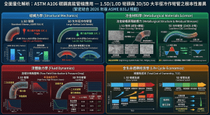
本研究旨在以學術深度剖析 ASTM A106 碳鋼材質在 CCPP 高能管線系統中的應用,並緊密結合 2026 年版 ASME B31J 規範,從結構力學、冶金材料學、流體動力學與全生命週期經濟學等多維度,全面量化解析傳統 1.5D/1.0D 彎頭與現代 3D/5D 大半徑冷作彎管之間的根本性差異。This study aims to provide an in-depth academic analysis of the application of ASTM A106 carbon steel in CCPP high-energy piping systems. By closely integrating the 2026 edition of the ASME B31J code, this research comprehensively and quantitatively analyzes the fundamental differences between traditional 1.5D/1.0D elbows and modern 3D/5D large-radius cold bends from multiple dimensions, including structural mechanics, metallurgical materials science, fluid dynamics, and life-cycle economics.
二、應力強化係數理論與法規演進:從Markl疲勞模型至ASME B31J / 2. Theory of Stress Intensification Factors and Code Evolution: From Markl’s Fatigue Model to ASME B31J
要深刻理解大半徑彎管與傳統銲接彎頭在受力狀態下的力學行為差異,必須首先回顧應力強化係數(SIF,代號 i)的物理意義及其法規演進歷程。當一段管線系統受到熱膨脹推力或外部彎矩作用時,有別於實心樑結構,空心圓管在彎曲處的橫截面會發生非線性的幾何變形,即所謂的「橢圓化(Ovalization)」現象7。在橢圓化的過程中,彎管的外弧側(Extrados)承受極大的拉伸應力而向內收縮,內弧側(Intrados)則承受強烈的壓縮應力而向外擠壓。這種橫截面的變形會大幅度地增加局部的彎曲應力,使得彎管的實際最大應力遠高於承受相同彎矩之相同外徑與壁厚的理想直管。為了在線性彈性管線分析軟體(如 CAESAR II 或 AutoPIPE)中模擬這種非線性應力激增現象,工程界引入了 SIF 作為名目應力的乘數11。To profoundly understand the mechanical behavioral differences between large-radius bends and traditional welded elbows under load, one must first review the physical significance of the Stress Intensification Factor (SIF, denoted as i) and its code evolution history. When a piping system is subjected to thermal expansion thrusts or external bending moments, unlike solid beam structures, the cross-section of a hollow circular pipe undergoes nonlinear geometric deformation at the bend, known as the “ovalization” phenomenon7. During ovalization, the extrados of the bend experiences immense tensile stress and contracts inward, while the intrados faces intense compressive stress and bulges outward. This cross-sectional deformation significantly amplifies the local bending stress, making the actual maximum stress of the bend much higher than that of an ideal straight pipe of the same outer diameter and wall thickness subjected to the same bending moment. To simulate this nonlinear stress surge in linear elastic piping analysis software (such as CAESAR II or AutoPIPE), the engineering community introduced the SIF as a multiplier for nominal stress11.
2.1 Markl疲勞測試與傳統附錄D之物理侷限性 / 2.1 Markl Fatigue Testing and the Physical Limitations of Traditional Appendix D
在舊版 ASME B31.1 與 B31.3 的應力計算框架中,SIF 的基礎數據主要源自於 A.R.C. Markl 於 1950 年代所進行的彎管交變疲勞破壞實驗。Markl 透過對各種管件施加反覆位移負載,記錄其破壞時的循環次數,並推導出著名的疲勞關聯方程式:In the stress calculation frameworks of older ASME B31.1 and B31.3 codes, the baseline data for SIFs primarily originated from the alternating fatigue failure experiments on pipe bends conducted by A.R.C. Markl in the 1950s. By applying repetitive displacement loads to various piping components and recording the number of cycles to failure, Markl derived the famous fatigue correlation equation:
i⋅S=C⋅N-0.2
在該公式中,S 代表計算出的名目應力振幅,N 為導致疲勞破壞的應力循環次數,而 C 為針對特定材料與測試條件所擬合出的常數9。基於這套疲勞數據,早期的 ASME B31.3 附錄D 提供了一套簡便的查表與封閉式數學公式來計算 SIF。然而,隨著現代管線系統的溫度與壓力不斷攀升,傳統附錄D 的物理侷限性與過度保守性開始顯露無遺。In this formula, S represents the calculated nominal stress amplitude, N is the number of stress cycles leading to fatigue failure, and C is a constant fitted for specific materials and test conditions9. Based on this fatigue data, the early ASME B31.3 Appendix D provided a simple set of look-up tables and closed-form mathematical formulas for calculating SIFs. However, as the temperatures and pressures of modern piping systems continue to climb, the physical limitations and excessive conservatism of the traditional Appendix D have become glaringly apparent.
傳統規範的最大缺陷在於,它將管件在三維空間中的複雜受力狀態過度簡化。對於多數元件而言,附錄D 僅計算出單一的 SIF 值,並將其強行套用於所有的力矩方向;即使有區分面內(In-plane)與面外(Out-of-plane)方向,其公式推導也往往基於極端保守的假設,且完全忽略了扭轉方向(Torsional)的應力強化效應(在舊規範中,扭轉 SIF 被預設為常數 1.0,忽略了扭轉剪應力在複雜幾何中的集中現象)7。這種粗略的計算方式導致工程師在設計 CCPP 管線時,經常高估了彎頭處的應力,進而被迫設計出過於龐大且冗長的熱膨脹補償迴路(Expansion Loops),這不僅浪費了昂貴的特殊合金鋼材,也增加了流體傳輸的壓降與泵浦能耗。The greatest flaw of the traditional codes lies in their oversimplification of the complex three-dimensional stress states of piping components. For most components, Appendix D calculated only a single SIF value and forcibly applied it to all moment directions. Even when distinguishing between in-plane and out-of-plane directions, the formula derivations were often based on extremely conservative assumptions and completely ignored the stress intensification effects in the torsional direction (in older codes, the torsional SIF was preset to a constant 1.0, ignoring the concentration of torsional shear stress in complex geometries)7. This rough calculation method often led engineers to overestimate the stress at elbows when designing CCPP pipelines, thereby forcing them to design overly large and lengthy thermal expansion loops. This not only wastes expensive specialty alloy steels but also increases the pressure drop of fluid transmission and pump energy consumption.
2.2 ASME B31J 的有限元素驗證與三維應力解耦矩陣 / 2.2 Finite Element Validation and 3D Stress Decoupling Matrix in ASME B31J
為了解決傳統規範的系統性誤差,ASME B31J-2026 規範標誌著管線應力分析正式邁入精確化與現代化的紀元。B31J 規範放棄了半個世紀前的簡化經驗公式,轉而採用高網格密度的三維殼元素(Shell Element)有限元素分析(FEA),並輔以嚴謹的實體應變計測試驗證(Strain-gauge testing)來建立標準數據庫8。在建立柔性因子的過程中,B31J 的研究團隊將受載荷的三維殼元素模型之變形量,與等效的線性彈性一維樑元素(1D Beam Element)模型之變形量進行對比,藉由兩者變形量的差異反向推導出柔性因子 k,確保商業軟體中的一維樑模型能夠精確重現真實三維管件的柔度特性16。To resolve the systematic errors of the traditional codes, the ASME B31J-2026 standard marks the official entry of piping stress analysis into an era of precision and modernization. The B31J code abandoned the simplified empirical formulas from over half a century ago, turning instead to high-mesh-density 3D Shell Element Finite Element Analysis (FEA), supplemented by rigorous physical strain-gauge testing validations to establish a standard database8. In establishing flexibility factors, the B31J research team compared the deformation of the loaded 3D shell element model with that of an equivalent linear elastic 1D Beam Element model. By inversely deriving the flexibility factor k from the difference in deformation between the two, they ensured that the 1D beam models in commercial software can accurately replicate the flexibility characteristics of real 3D piping components16.
B31J 規範最具革命性的突破在於「應力解耦(Stress Decoupling)」。它針對管件的三個正交方向:面內彎曲(In-plane bending,使彎管像鉸鏈般開合的力矩)、面外彎曲(Out-of-plane bending,使彎管發生扭曲的力矩)以及扭轉(Torsional),分別提供了獨立的 SIF 數值與柔性因子計算公式8。根據 ASME B31J 表 1-1(Table 1-1),對於無縫銲接彎頭與冷作彎管(Welding elbow or pipe bend),其應力強化與柔性行為取決於一項關鍵的幾何無因次參數,稱為「柔性特徵值(Flexibility Characteristic)」,代號為 h:The most revolutionary breakthrough of the B31J code lies in “Stress Decoupling.” It provides independent SIF values and flexibility factor calculation formulas for the three orthogonal directions of the piping component: in-plane bending (a moment that causes the bend to open or close like a hinge), out-of-plane bending (a moment that twists the bend), and torsional8. According to ASME B31J Table 1-1, for welding elbows or pipe bends, their stress intensification and flexibility behaviors depend on a critical dimensionless geometric parameter known as the “Flexibility Characteristic,” denoted as h:
h=T⋅R1/r22
在該定義中:In this definition:
- T 代表彎管的標稱壁厚。T represents the nominal wall thickness of the bend.
- R1 代表彎管的曲率中心半徑。R1 represents the bend radius of the welding elbow or pipe bend.
- r2 代表與之匹配之直管的平均半徑(Mean radius of matching pipe),其值等於(Do-T)/2 14。 參數 h 量化了幾何變異對管件柔性的綜合影響。當管壁變厚(T 增加)或曲率半徑拉大(R1 增加)時,h 的數值會隨之上升。物理上,h 值的增大意味著管件在承受彎矩時,抗橢圓化的剛性越強,其整體行為會越接近於未產生應力集中的理想直管14。r2 represents the mean radius of the matching pipe, calculated as (Do-T)/2 14. The parameter h quantifies the comprehensive impact of geometric variations on the component’s flexibility. As the wall thickness increases (increase in T) or the bend radius enlarges (increase in R1), the value of h rises accordingly. Physically, a larger h value implies that the component has stronger rigidity against ovalization when subjected to a bending moment, and its overall behavior more closely resembles an ideal straight pipe with no stress concentration14.
依據 B31J 的精確定義,彎管在不同受力方向上的 SIF 與柔性因子 k 之計算公式如下:According to the precise definitions in B31J, the formulas for calculating the SIFs and flexibility factor k of bends in different loading directions are as follows:
面內應力強化係數 (In-plane SIF, ii ):
ii=0.9/h2/3
面外應力強化係數 (Out-of-plane SIF, io):
Io=0.75/h2/3
扭轉應力強化係數 (Torsional SIF, it):B31J 針對彎管通常給予基礎值 1.0,但會依據相鄰端點的剛性邊界條件進行特定折減或修正15。B31J generally assigns a base value of 1.0 for bends, but specific reductions or corrections may be applied based on the rigid boundary conditions at adjacent ends15.
柔性因子 (Flexibility Factor, k):
k=1.65/h
B31J 規範條文嚴格確立了一項邊界條件:所有計算出的 SIF 值均不得小於絕對下限 1.0(因為 1.0 代表理想直管的光滑應力狀態,任何幾何變異不可能使應力低於完美直管);同時,若計算出的柔性因子 k 小於 1.0,則在分析中必須將該元件視為完全剛體(Rigid)處理14。The B31J code strictly establishes a boundary condition: all calculated SIF values must not be less than the absolute minimum of 1.0 (since 1.0 represents the smooth stress state of an ideal straight pipe, and no geometric variation can result in a stress lower than a perfect straight pipe); meanwhile, if the calculated flexibility factor k is less than 1.0, the component must be treated as completely rigid in the analysis14.
三、基於 ASME B31J-2026 之 1.5D / 3D / 5D 彎管應力場與柔性因子深度解析 / 3. In-Depth Analysis of Stress Fields and Flexibility Factors for 1.5D / 3D / 5D Bends Based on ASME B31J-2026
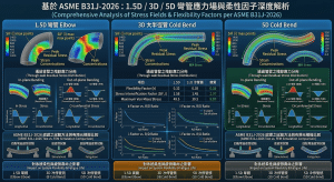
為了將上述的法規理論轉化為具體的工程量化數據,並深刻揭示 1.5D 銲接彎頭與 5D 大半徑冷作彎管之間的力學鴻溝,本段落將導入一組 CCPP HRSG 系統中常見的高壓給水管線參數,進行基於 ASME B31J 的精確數值推導21。 我們選定一條美國國家標準管徑 NPS 8 吋的碳鋼管線作為基準模型,其幾何邊界條件設定如下:To translate the aforementioned code theories into concrete, quantified engineering data and profoundly reveal the mechanical chasm between 1.5D welded elbows and 5D large-radius cold bends, this section will introduce a set of high-pressure feedwater piping parameters common in CCPP HRSG systems to conduct precise numerical derivations based on ASME B31J21. We select an NPS 8-inch standard carbon steel pipe as the baseline model, with geometric boundary conditions set as follows:
- 管線外徑/Pipe outside diameter(Do):8.625 inch
- 管線壁厚/Pipe wall thickness (Schedule 40, i.e., T):0.322 inch
- 匹配直管之平均半徑(r2)/ Mean radius of matching pipe (r2):計算得/calculated as (8.625-0.322)/2=4.1515 inch
在探討不同加工工法產出的彎管元件時,其最根本的幾何變數在於曲率半徑 R1:When exploring bend components produced by different manufacturing methods, the most fundamental geometric variable is the bend radius R1:
- 傳統1.5D 彎頭:/ Traditional 1.5D Elbow: R1=1.5*8=12.0 inch
- 大半徑 3D 冷作彎管:/ Large-Radius 3D Cold Bend: R1=3.0*8=24.0 inch
- 大半徑 5D 冷作彎管:/Large-Radius 5D Cold Bend: R1=5.0*8=40.0 inch
將上述參數代入 B31J 的 h 函數與相關公式中,可得出一系列反映應力集中程度與柔性變形能力的關鍵指標,詳列於下表:Substituting these parameters into the B31J h function and related formulas yields a series of key indicators reflecting the degree of stress concentration and flexible deformation capacity, detailed in the table below:
| 參數 / Parameter | 傳統 1.5D 彎頭 / Traditional 1.5D Elbow | 3D 冷作彎管 / 3D Cold Bend | 5D 冷作彎管 / 5D Cold Bend | 理想直管下限 / Ideal Pipe Lower Limit |
| 曲率半徑 / Bend Radius R1 (inch) | 12.0 | 24.0 | 40.0 | |
| 柔性特徵值 / Flexibility Characteristic h | 0.224 | 0.448 | 0.747 | |
| 柔性因子 / Flexibility Factor k | 7.37 | 3.68 | 2.21 | 1.0 |
| 面內 / In-plane SIF (ii) | 2.44 | 1.54 | 1.09 | 1.0 |
| 面外 / Out-of-plane SIF (io) | 2.03 | 1.28 | 1.00 (Calc: 0.91) | 1.0 |
對比上述數值矩陣,可以觀察到幾何演化在控制應力集中效應上具有決定性的主導權。當系統採用傳統的 1.5D 彎頭時,其面內應力強化係數高達 2.44;這在物理上意味著,當相同的熱膨脹彎矩作用於該彎頭時,發生在彎頭側壁中性軸附近的極值彎曲應力,將是旁邊連接直管名目應力的 2.44 倍。這種急遽攀升的應力峰值,正是 CCPP 高能管線在經歷無數次冷爐啟動、熱爐跳機的劇烈溫度循環後,容易於彎頭銲道與內弧側產生低週疲勞裂紋(Low-cycle Fatigue Cracking)的力學根源12。Comparing the numerical matrix above, it can be observed that geometric evolution wields decisive authority in controlling stress concentration effects. When a system employs traditional 1.5D elbows, the in-plane SIF reaches as high as 2.44; physically, this means that when the same thermal expansion bending moment is applied to the elbow, the extreme bending stress occurring near the neutral axis of the elbow’s sidewall will be 2.44 times the nominal stress of the adjacent connected straight pipe. This sharply escalating stress peak is precisely the mechanical root cause behind the susceptibility of CCPP high-energy piping to low-cycle fatigue cracking at elbow welds and intrados after enduring countless severe temperature cycles of cold starts and hot trips12.
反觀採用數控冷作工法製成的 5D 大半徑彎管,由於其曲率半徑大幅拉長,使得彎管在受彎矩時的橫截面橢圓化效應被極大地削弱。5D 彎管的面內 SIF 急遽下降至微不足道的 1.09;更驚人的是,其面外 SIF 的純數學計算值已低於 1.0(約 0.91),依法規強制平準化至絕對下限 1.014。這意味著在面外扭曲載荷下,5D 彎管的應力分佈已經與完美直管完全等效,應力集中現象被徹底消除。Conversely, for 5D large-radius bends manufactured via CNC cold bending, their significantly extended bend radius vastly mitigates the cross-sectional ovalization effect when subjected to a bending moment. The in-plane SIF of the 5D bend sharply drops to a negligible 1.09; even more remarkably, the purely mathematical calculation for its out-of-plane SIF falls below 1.0 (approximately 0.91), which the code mandates to be leveled up to the absolute lower limit of 1.014. This signifies that under out-of-plane torsional loads, the stress distribution of a 5D bend is completely equivalent to that of a perfect straight pipe, with stress concentration phenomena entirely eliminated.
此外,在評估管線因自重與內部壓力等一次性負載(Primary Loads)所引發的破壞風險時,ASME B31.1 動力管線規範定義了「持續應力指數(Sustained Stress Index, SSI)」,該指數計算方式為 I = max(0.75 , 1.0),用於防止管線系統發生塑性崩塌8。由於 5D 彎管的各項 SIF 皆已逼近 1.0,其持續應力指數將完全退化為常數 1.0。這種將「彎管力學行為完全直管化」的特徵,賦予了 5D 彎管在抵抗高溫潛變與持續機械負載上無與倫比的安全裕度8。Furthermore, when evaluating the failure risks induced by primary loads such as dead weight and internal pressure, the ASME B31.1 Power Piping code defines the “Sustained Stress Index” (SSI), calculated as I = max(0.75 , 1.0), intended to prevent plastic collapse in the piping system8. Because all SIFs of the 5D bend closely approach 1.0, its SSI completely degenerates into a constant 1.0. This characteristic of “fully converting bend mechanical behavior into straight-pipe equivalents” endows 5D bends with an unparalleled safety margin against high-temperature creep and sustained mechanical loads8.
四、ASTM A106 碳鋼材料特性與 B31.1 / B31.3 高溫規範應用 / 4. ASTM A106 Carbon Steel Material Properties and High-Temperature Code Applications (B31.1 / B31.3)
在建構具備極高力學穩定性的宏觀幾何形狀之後,構成 CCPP 高能管線的微觀冶金材質同樣是決定系統壽命的關鍵。在化石燃料電廠與複循環機組的給水、凝結水、鍋爐排放及中低壓蒸汽系統中,ASTM A106 高溫無縫碳鋼管(Seamless Carbon Steel Pipe for High-Temperature Service)是全球業界無可取代的絕對主力標準規範21。After establishing macroscopic geometries with extremely high mechanical stability, the microscopic metallurgical materials constituting the CCPP high-energy piping are equally critical in determining the system’s lifespan. In the feedwater, condensate, boiler blowdown, and low-to-medium pressure steam systems of fossil fuel power plants and combined cycle units, ASTM A106 Seamless Carbon Steel Pipe for High-Temperature Service is the globally irreplaceable, absolute mainstream standard21.
依據 ASME B31.3 製程管線與 B31.1 動力管線規範的高溫容許應力表(Table A-1),ASTM A106 碳鋼材料被許可於最高約 427°C(800°F)的環境下長期服役;在滿足特定壽命評估與壁厚餘裕的條件下,其最高金屬溫度限制甚至可進一步放寬至 482°C28。值得注意的是,B31.1 與 B31.3 在設計哲學與安全係數的取用上存在根本性的差異:B31.1 作為規範發電廠關鍵生命線的準則,其在低至中溫範圍內採用了極為嚴格的 4:1 安全係數(以常溫抗拉強度為基準),以反映發電設備對長達數十年連續運轉的極端可靠性要求;而針對化學製程的 B31.3 規範,則允許採用較為經濟的 3:1 安全係數,這也是為何同一管材在兩種規範下,其查表所得的容許應力值會有所不同的底層邏輯30。According to the high-temperature allowable stress tables (Table A-1) of the ASME B31.3 Process Piping and B31.1 Power Piping codes, ASTM A106 carbon steel materials are permitted for long-term service in environments up to approximately 427°C (800°F); under conditions meeting specific life assessments and wall thickness margins, its maximum metal temperature limit can even be relaxed to 482°C28. It is worth noting that fundamental differences exist between B31.1 and B31.3 in their design philosophies and selection of safety factors: B31.1, acting as the guideline for the critical lifelines of power plants, adopts an extremely stringent 4:1 safety factor (based on ambient tensile strength) in the low-to-medium temperature range to reflect the extreme reliability requirements of power generation equipment for decades of continuous operation. Conversely, the B31.3 code for chemical processes permits a more economical 3:1 safety factor, which is the underlying logic as to why the allowable stress values obtained from look-up tables for the same pipe material differ between the two codes30.
4.1 Grade B 與 Grade C 之微觀冶金與選型博弈 / 4.1 Micro-Metallurgy and Selection Strategy of Grade B vs. Grade C
ASTM A106 規範下涵蓋了不同的強度等級,其中工程實務上最常面臨抉擇的是 Grade B 與 Grade C。這兩個等級的差異,深刻體現了冶金工程中碳含量與機械強度、銲接性之間的微妙平衡:The ASTM A106 standard covers different strength grades, among which Grade B and Grade C are the most frequently faced choices in engineering practice. The differences between these two grades profoundly reflect the delicate balance in metallurgical engineering among carbon content, mechanical strength, and weldability:
- A106 Grade B:作為工業界的預設標準,其規範要求最小降伏強度為 35,000 psi,最小抗拉強度為 60,000 psi。為確保優異的加工性與現場銲接穩定性,其碳當量(Carbon Equivalent, CE)通常被嚴格控制在35% 至 0.40% 之間。由於其供應鏈極度普及且價格最具競爭力,A106 Grade B 成為了 427°C 以下絕大多數製程與動力管線的首選21。A106 Grade B: As the default standard in the industry, its specification requires a minimum yield strength of 35,000 psi and a minimum tensile strength of 60,000 psi. To ensure excellent machinability and on-site welding stability, its Carbon Equivalent (CE) is usually strictly controlled between 0.35% and 0.40%. Due to its highly ubiquitous supply chain and most competitive pricing, A106 Grade B has become the top choice for the vast majority of process and power piping below 427°C21.
- A106 Grade C:其透過增加碳含量來提升常溫與高溫強度,規範要求最小降伏強度達 40,000 psi,抗拉強度達 70,000 psi。其碳含量允許值上限提高至40% 到 0.45% 區間。當操作溫度突破 400°C 逼近材料極限值時,Grade C 在 ASME Table A-1 中的高溫容許應力衰退幅度較小,其強度優勢將顯著拉開與 Grade B 的差距21。A106 Grade C: It enhances both ambient and high-temperature strength by increasing carbon content, with specifications requiring a minimum yield strength of 40,000 psi and a tensile strength of 70,000 psi. Its allowable upper limit for carbon content is raised to the 0.40% to 0.45% range. When operating temperatures exceed 400°C and approach the material’s limit, the decline in high-temperature allowable stress for Grade C in ASME Table A-1 is smaller, and its strength advantage will significantly widen the gap with Grade B21.
雖然從純粹的壓力壁厚計算公式(t=P⋅D/2(S⋅E+P⋅Y))來看,採用高容許應力(S)的 A106 Grade C 能夠顯著縮減管線的設計壁厚,進而減少整體鋼材噸數並抵銷其較高的單位採購溢價28;但高碳含量帶來的副作用卻是現場施工的夢魘。隨著碳當量的提升,Grade C 鋼材在冷卻速率較快的現場銲接環境中,極易於熱影響區(HAZ)產生脆性的麻田散鐵組織,進而誘發致命的氫致延遲裂紋(Hydrogen-induced Cracking)。因此,相關規範嚴格要求,當 Grade C 管線壁厚超過 25mm 時,必須強制進行 50°C-100°C 的銲前預熱;若壁厚超過 40mm,預熱溫度更需提升至 150°C-200°C,並且必須嚴格管制並全程使用低氫型銲條28。基於整體施工穩定性、現場品保查核難度以及供應鏈交期的綜合考量,除非 CCPP 設計壓力極高導致 Grade B 的壁厚變得極端不合理,否則工程業界普遍維持採用 A106 Grade B 作為高能管線的最佳平衡點。Although purely from the pressure wall thickness calculation formula (t=P⋅D/2(S⋅E+P⋅Y)), employing A106 Grade C with its higher allowable stress (S) can significantly reduce the pipeline’s design wall thickness, thereby decreasing overall steel tonnage and offsetting its higher unit procurement premium28; the side effects of higher carbon content are a nightmare for on-site construction. As the carbon equivalent rises, Grade C steel is highly prone to forming brittle martensitic microstructures in the Heat-Affected Zone (HAZ) during on-site welding environments with rapid cooling rates, which in turn induces fatal Hydrogen-induced Cracking. Therefore, relevant codes strictly mandate that when Grade C pipe wall thickness exceeds 25mm, preheating at 50°C-100°C must be enforced; if the wall thickness exceeds 40mm, the preheat temperature must be further raised to 150°C-200°C, and low-hydrogen electrodes must be strictly controlled and utilized throughout28. Based on comprehensive considerations of overall construction stability, the difficulty of on-site quality assurance audits, and supply chain lead times, unless the CCPP design pressure is extremely high making Grade B’s wall thickness grossly impractical, the engineering industry universally maintains the use of A106 Grade B as the optimal balancing point for high-energy piping.
在實際工程參數參考上,以 ASME B31.1 動力管線規範下的 ASTM A106 Grade B 碳鋼為例,當操作溫度設定為 100°F 至 650°F 的區間內,其設計容許應力穩定維持在 15,000 psi 至 20,000 psi 之間;然而,一旦流體溫度跨越 700°F 甚至逼近 750°F,材料內部的晶界滑移與高溫軟化效應開始加劇,其容許應力將發生斷崖式的衰減,此時就必須仰賴精密計算與更厚的壁厚餘裕來確保管線不發生潛變破裂33。For practical engineering parameter references, taking ASTM A106 Grade B carbon steel under the ASME B31.1 Power Piping code as an example, when the operating temperature is set within the range of 100°F to 650°F, its design allowable stress stably remains between 15,000 psi and 20,000 psi. However, once the fluid temperature crosses 700°F or even approaches 750°F, grain boundary sliding and high-temperature softening effects within the material begin to intensify, and its allowable stress will experience a precipitous decline. At this point, engineers must rely on precise calculations and thicker wall margins to ensure the pipeline does not suffer creep rupture33.
五、彎管加工製程之熱處理與冶金邊界條件:彎後熱處理 (PBHT) 之必要性 / 5. Heat Treatment and Metallurgical Boundary Conditions in the Bending Process: The Necessity of Post-Bend Heat Treatment (PBHT)
確認了 A106 Grade B 碳鋼材料與最佳的 5D 大半徑幾何後,將筆直的無縫碳鋼管轉化為彎管的加工製程,是決定最終管件品質的另一道難關。當直管被送入數控感應彎管機或冷彎機進行大角度彎曲時,金屬晶格將被迫承受超越其彈性極限值的劇烈塑性變形。在彎曲成型的過程中,彎管外側(Extrados)的材料被拉伸,導致不可避免的壁厚減薄(Wall Thinning);而內弧側(Intrados)則受到極大的壓應力擠壓而增厚,並伴隨橫截面的橢圓化變形(Flattening/Ovality)35。After confirming the A106 Grade B carbon steel material and the optimal 5D large-radius geometry, the manufacturing process that transforms a straight seamless carbon steel pipe into a bend poses another hurdle that determines the final component’s quality. When straight pipes are fed into CNC induction bending machines or cold bending machines for large-angle bending, the metal lattice is forced to endure severe plastic deformation exceeding its elastic limits. During the bending and forming process, the material on the outer side of the bend (Extrados) is stretched, leading to inevitable Wall Thinning; meanwhile, the inner side (Intrados) is subjected to immense compressive stress, causing it to thicken, accompanied by the ovalization (Flattening) of the cross-section35.
為了科學化量測並管制此一塑性變形造成的材料損傷,ASME B31.1 第 129 節(Bending and Forming)及 2026 年最新修訂版,嚴格定義了冷彎應變(Cold Bending Strain, ϵ)的計算模型。理論彎曲應變的極值發生在管壁的最外緣,其數學公式定義為:To scientifically measure and regulate the material damage caused by this plastic deformation, ASME B31.1 Section 129 (Bending and Forming) and its latest 2026 revision strictly define the calculation model for Cold Bending Strain (ϵ). The extreme value of theoretical bending strain occurs at the outermost edge of the pipe wall, and its mathematical formula is defined as:
ϵ=r/R1 =Do/(2R1)×100%
其中,Do 為管件外徑,R1 為彎曲中心半徑37。我們將前述 1.5D 與 5D 彎管的規格代入此應變模型進行對比:Where Do is the component’s outside diameter, and R1 is the bend radius37. We substitute the specifications of the aforementioned 1.5D and 5D bends into this strain model for comparison:
- 傳統1.5D 彎頭的理論彎曲應變/Theoretical bending strain of traditional 1.5D elbows::ϵ=1/(2×1.5)≈33.3%
- 現代 5D 彎管的理論彎曲應變/Theoretical bending strain of modern 5D bends::ϵ=1/(2×5.0)=10.0%
這組數據揭露了一個關鍵的工程事實:1.5D 彎曲加工所伴隨的高達 33.3% 的應變率,已遠遠超過常溫下碳鋼的塑性變形容受極限值。因此,製造 1.5D 彎頭通常必須在材料的相變溫度(Transformation Range)之上,採用熱推成型(Hot Forming)或高頻感應熱彎工法來完成。相對而言,5D 大半徑彎管因其應變率被嚴格控制在 10% 的低限,可以順利採用室溫下的 CNC 冷彎工法(Cold bending is done at a temperature below the transformation range),從而避免了高溫加熱對碳鋼微觀組織的不可控改變37。This set of data reveals a crucial engineering fact: the massive 33.3% strain rate accompanying 1.5D bending processes far exceeds the tolerance limit for plastic deformation of carbon steel at room temperature. Therefore, manufacturing 1.5D elbows typically requires Hot Forming or high-frequency induction hot bending processes above the material’s Transformation Range. In contrast, because the strain rate of 5D large-radius bends is strictly controlled at the lower limit of 10%, they can seamlessly utilize CNC cold bending processes at room temperature (Cold bending is done at a temperature below the transformation range), thereby avoiding uncontrollable alterations to the carbon steel’s microstructure caused by high-temperature heating37.
然而,即使 5D 冷作彎管將應變率壓低至 10%,冷加工過程中所引發的應變硬化(Strain Hardening)效應仍會在 A106 碳鋼內部殘留龐大的微觀內應力。這些殘留應力會導致晶格嚴重扭曲、差排密度激增,在宏觀上表現為材料局部降伏強度異常攀升、延展性驟降,以及對抵禦脆性破壞至關重要的斷裂韌性(Fracture Toughness)嚴重流失。However, even though 5D cold bends suppress the strain rate to 10%, the Strain Hardening effects induced during cold processing still leave massive microscopic internal stresses residing within the A106 carbon steel. These residual stresses cause severe lattice distortion and a surge in dislocation density, manifesting macroscopically as an abnormal escalation in localized yield strength, a plunge in ductility, and a severe loss of Fracture Toughness, which is vital for resisting brittle failure.
為了徹底根除這些潛在的冶金隱患,確保管線在 CCPP 高溫、高壓長期運轉下的安全性,ASME B31.1 第 129.3 節強制要求對承受顯著冷彎應變的管件介入彎後熱處理(Post-Bend Heat Treatment, PBHT,亦常與銲後熱處理 PWHT / SRHT 通用標準)39。依據規範表 132 針對 P-No.1 碳鋼(含 A106)的規定,PBHT 必須將彎管置於控溫爐中,精確升溫至規範指定的退火溫度區間(通常為 595°C 至 650°C 之間),並根據管線的最大壁厚嚴格維持指定的保溫時間(Holding Time,一般為每英吋壁厚保溫一小時),最後再以受控的速率緩慢冷卻41。這段精密的熱力學循環,能驅動碳鋼內部的金屬晶粒經歷應力回復(Recovery)與再結晶(Recrystallization)的冶金程序,消除差排堆積,最終將加工區域的機械特性與抗疲勞能力完美恢復至與原始直管無異的健康狀態6。To completely eradicate these potential metallurgical hidden dangers and ensure the safety of pipelines under long-term high-temperature and high-pressure operation in CCPPs, ASME B31.1 Section 129.3 mandates the intervention of Post-Bend Heat Treatment (PBHT, often sharing universal standards with Post-Weld Heat Treatment PWHT / SRHT) for components subjected to significant cold bending strain39. According to the provisions of Code Table 132 for P-No.1 carbon steels (including A106), PBHT requires placing the bend in a temperature-controlled furnace, precisely raising the temperature to the code-specified annealing temperature range (typically between 595°C and 650°C), strictly maintaining the specified Holding Time based on the maximum wall thickness of the pipe (generally one hour per inch of wall thickness), and finally cooling slowly at a controlled rate41. This precise thermodynamic cycle drives the metal grains within the carbon steel to undergo metallurgical processes of Recovery and Recrystallization, eliminating dislocation pile-ups, and ultimately perfectly restoring the mechanical properties and fatigue resistance of the processed area to a healthy state identical to the original straight pipe6.
六、幾何演化對流體動力學與流體加速腐蝕 (FAC) 之深度耦合分析 / 6. Deep Coupling Analysis of Geometric Evolution on Fluid Dynamics and Flow-Accelerated Corrosion (FAC)
在複循環電廠的生命週期中,HRSG 與給水系統內的純水或汽水兩相流長期以極高的流速在封閉管線網路中循環。這種看似潔淨的流體,實則蘊藏著極強的物理破壞力,常導致管壁材料在流動剪應力與化學溶解的雙重作用下快速流失,即工程界聞之色變的流體加速腐蝕(Flow-Accelerated Corrosion, FAC)。實務統計表明,高能管線中的彎管部位向來是 FAC 的重災區;而 FAC 的侵蝕速率,與彎管內部的流場紊流強度、二次流(Secondary Flow)的三維分佈,以及流動邊界層(Boundary Layer)的厚度變化有著密不可分的函數關係1。Throughout the life cycle of a combined cycle power plant, pure water or steam-water two-phase flows within the HRSG and feedwater systems circulate continuously at extremely high velocities within closed piping networks. This seemingly clean fluid actually harbors immensely strong physical destructive power, often causing rapid material loss on pipe walls under the dual actions of flow shear stress and chemical dissolution—a phenomenon the engineering community dreads, known as Flow-Accelerated Corrosion (FAC). Empirical statistics show that bend sections in high-energy piping have always been disaster zones for FAC; moreover, the erosion rate of FAC possesses an inseparable functional relationship with the turbulence intensity of the flow field inside the bend, the three-dimensional distribution of Secondary Flow, and variations in Boundary Layer thickness1.
6.1 傳統 1.5D 彎頭的流固耦合劣勢與渦流崩潰 / 6.1 Fluid-Solid Coupling Disadvantages and Vortex Breakdown in Traditional 1.5D Elbows
當高速流體從直管段猛然沖入 1.5D 短半徑彎頭時,流道曲率的劇烈變化會瞬間打破流體的層流或穩定紊流狀態。受強大離心力的驅使,流管內的高速核心流(Core Flow)會被強制甩向彎管的外弧側,以極高的動能猛烈撞擊背弧(Extrados)管壁。更為致命的是,在彎管的內弧側(Intrados),由於流體被迫進行急轉彎,沿流線方向會產生極強的逆壓梯度(Adverse Pressure Gradient)。這種壓力反轉現象會導致內弧側的流動邊界層發生大規模分離(Flow Separation),流體無法繼續貼附管壁,進而在分離點後方形成廣泛的尾流漩渦區與逆流區1。When high-speed fluid abruptly rushes from a straight pipe section into a 1.5D short-radius elbow, the drastic change in flow channel curvature instantly shatters the fluid’s laminar or steady turbulent state. Driven by powerful centrifugal forces, the high-speed Core Flow within the stream tube is forcefully flung toward the outer curve of the bend, violently impacting the Extrados pipe wall with extreme kinetic energy. Even more fatally, on the inner curve of the bend (Intrados), as the fluid is forced to make a sharp turn, an extremely strong Adverse Pressure Gradient is generated along the streamline direction. This pressure inversion phenomenon causes large-scale Flow Separation in the boundary layer on the inner curve; the fluid can no longer adhere to the pipe wall, consequently forming expansive wake vortex zones and reverse flow regions behind the separation point1.
這種強烈的流體力學擾動產生了兩大災難性的破壞機制:This intense fluid mechanical disturbance generates two catastrophic destruction mechanisms:
- 二次流與對流質傳遞速率極大化:強大的紊流與流體剪應力會持續剝離碳鋼管壁內部原本具有保護作用的緻密氧化層(如磁鐵礦 Magnetite 層)。一旦保護膜被沖刷殆盡,新鮮的鐵基材便會直接暴露於高溫溶氧流體中,加速化學溶解反應,使得 FAC 速率呈指數級上升,最終導致管壁異常減薄甚至無預警爆管1。Maximization of Secondary Flow and Convective Mass Transfer Rates: Powerful turbulence and fluid shear stress continuously strip away the dense oxide layer (such as the Magnetite layer) inside the carbon steel pipe wall, which originally served a protective function. Once the protective film is scoured away, the fresh iron substrate is directly exposed to high-temperature dissolved oxygen fluid, accelerating chemical dissolution reactions, causing FAC rates to rise exponentially, and ultimately leading to abnormal wall thinning or even unpredicted pipe bursts1.
- 局部動態壓力降與高頻振動:嚴重的紊流與漩渦會造成龐大的不可逆流體動能損失(壓降)。更糟的是,邊界層分離所伴隨的渦流脫落(Vortex Shedding)會誘發高頻率的流體誘發振動(Fluid-Induced Vibration, FIV)。這種反覆的交變動態載荷,若與1.5D 彎頭本身高達 2.44 的面內應力強化係數(SIF)產生共振與疊加,將使管件極速步入疲勞破壞的深淵45。Localized Dynamic Pressure Drops and High-Frequency Vibration: Severe turbulence and vortices cause massive irreversible fluid kinetic energy losses (pressure drops). Worse still, the Vortex Shedding accompanying boundary layer separation induces high-frequency Fluid-Induced Vibration (FIV). If these repetitive alternating dynamic loads resonate and superimpose with the 1.5D elbow’s own incredibly high in-plane SIF of 2.44, the component will rapidly plunge into the abyss of fatigue failure45.
6.2 5D 大半徑冷作彎管的氣動力學優勢與護膜效應 / 6.2 Aerodynamic Advantages and Film Protection Effects of 5D Large-Radius Cold Bends
與 1.5D 彎頭形成鮮明物理對比的是,5D 大半徑彎管透過極度平緩的曲率過渡,徹底重塑了微觀與宏觀的流場結構。當流體進入 5D 彎管時,用以改變流向的離心力被均勻分散至更長、更平緩的圓弧區間。流體的速度剖面(Velocity Profile)得以維持相對對稱與均勻,內弧側的逆壓梯度被大幅削弱,從根本上消除了邊界層分離與渦流生成的氣動力學條件3。Forming a stark physical contrast with 1.5D elbows, 5D large-radius bends completely reshape the micro and macro flow field structures through extremely gentle curvature transitions. When fluid enters a 5D bend, the centrifugal forces used to change flow direction are evenly distributed over a longer, gentler arc interval. The fluid’s Velocity Profile is maintained relatively symmetrical and uniform, and the adverse pressure gradient on the intrados is massively weakened, fundamentally eliminating the aerodynamic conditions for boundary layer separation and vortex generation3.
由於流線能夠完美緊貼著 5D 彎管的內外管壁平順流動,管壁表面得以維持穩定且具有一定厚度的黏滯次層(Viscous Sublayer)。這一層極薄且流速緩慢的流體層扮演了關鍵的緩衝角色,它大幅降低了流體向管壁的對流質傳遞速率(Mass Transfer Rate)。在這種溫和的流體力學環境下,A106 碳鋼表面的磁鐵礦保護膜得以穩定生長而不被沖刷剝離,有效阻絕了 FAC 的侵蝕路徑。同時,平緩順暢的流場消除了分離渦流帶來的壓力損失,長年累月下來,能顯著節省 CCPP 給水泵(Feedwater Pump)的持續電能消耗,創造可觀的營運效益1。Because streamlines can perfectly hug the inner and outer walls of the 5D bend and flow smoothly, a stable Viscous Sublayer with a certain thickness is maintained on the pipe wall surface. This extremely thin, slow-moving fluid layer plays a critical buffering role; it drastically reduces the convective Mass Transfer Rate of the fluid towards the pipe wall. Under this mild fluid mechanical environment, the protective magnetite film on the A106 carbon steel surface can grow stably without being scoured and peeled away, effectively blocking the invasion pathways of FAC. Simultaneously, the gentle and smooth flow field eliminates the pressure losses caused by separation vortices. Over years and months, this can significantly save continuous electrical energy consumption for CCPP Feedwater Pumps, creating considerable operational benefits1.
七、系統佈局最佳化、熱膨脹管理與經濟性全生命週期成本 (LCC) 評估 / 7. Optimization of System Layout, Thermal Expansion Management, and Economic Life-Cycle Cost (LCC) Evaluation
除了單一管線元件在微觀應力與局部流體行為上的優勢外,將 5D 大半徑冷作彎管取代 1.5D 彎頭並整合至宏觀的 CCPP 工廠管線網路中,將為系統佈局、熱膨脹管理與專案經濟學帶來深遠的系統性變革。Beyond the advantages of single piping components in terms of micro-stress and localized fluid behavior, replacing 1.5D elbows with 5D large-radius cold bends and integrating them into the macroscopic CCPP plant piping networks will bring profound systemic transformations to system layout, thermal expansion management, and project economics.
7.1 柔性因子與空間足跡 (Footprint) 的幾何博弈 / 7.1 The Geometric Game Between Flexibility Factors and Spatial Footprints
CCPP 的主蒸汽與高溫給水管線(操作溫度動輒高達 300°C 至 400°C)在開機受熱後會產生巨大的線性熱膨脹量。在管線工程中,設計師無法抑制這些膨脹,只能利用管線本身的幾何彈性,透過設計 Z 型、L 型或 U 型熱膨脹補償迴路(Expansion Loops)來吸收這些龐大的位移量48。The main steam and high-temperature feedwater piping in CCPPs (with operating temperatures routinely reaching 300°C to 400°C) generate massive linear thermal expansions after being heated during startup. In piping engineering, designers cannot suppress these expansions; they can only utilize the geometric elasticity of the piping itself by designing Z-type, L-type, or U-type Expansion Loops to absorb these massive displacement amounts48.
在熱膨脹的計算中,彎管的柔性因子(Flexibility Factor, k)扮演了雙刃劍的矛盾角色。如前文 B31J 數值解析所示,1.5D 彎頭的 k 值高達 7.37,遠大於 5D 彎管的 2.218。單純從剛度矩陣來看,1.5D 彎頭因為在受力時極易發生橫截面橢圓化變形,能夠像彈簧一樣吸收更多的旋轉位移,提供管網極高的局部柔性。然而,這是一種飲鴆止渴的設計機制,因為這種高柔性是建立在「以犧牲元件疲勞壽命換取局部極端變形」的高風險基礎上(伴隨極高的 SIF)。In calculating thermal expansion, the component’s Flexibility Factor (k) plays the paradoxical role of a double-edged sword. As demonstrated in the previous B31J numerical analysis, the 1.5D elbow possesses a k value of 7.37, vastly higher than the 5D bend’s 2.218. Purely from a stiffness matrix perspective, because 1.5D elbows are highly prone to cross-sectional ovalization when loaded, they can absorb more rotational displacement just like a spring, providing the piping network with extremely high local flexibility. However, this is a self-destructive design mechanism, as this high flexibility is built on the high-risk foundation of “trading component fatigue life for extreme local deformation” (accompanied by extremely high SIFs).
相對而言,5D 大半徑彎管本身的 k 值較低,結構較為剛硬。為了轉彎,5D 彎管需要消耗比 1.5D 彎頭大得多的幾何半徑,在空間受限的工廠中佔用較大的空間足跡(Footprint)22。但是,由於 5D 彎管的應力強化係數幾乎等同於 1.0,整體管線網路在承受同樣的熱膨脹位移時,不會在彎管處產生致命的應力尖峰。這賦予了管線應力工程師極大的系統調度彈性,使得整體熱膨脹迴路的尺度反而可以大膽縮小,最終在宏觀層面上最佳化了工廠空間的立體配置,並減少了龐大的鋼結構支撐成本。Comparatively, the 5D large-radius bend itself has a lower k value and is structurally more rigid. To make a turn, a 5D bend consumes a geometric radius much larger than a 1.5D elbow, occupying a larger spatial Footprint in space-constrained plants22. However, because the SIF of a 5D bend is nearly equivalent to 1.0, the overall piping network will not generate fatal stress peaks at the bends when enduring the same thermal expansion displacement. This grants piping stress engineers immense flexibility in system dispatching, allowing the scale of the overall thermal expansion loops to actually be boldly reduced. Ultimately, on a macroscopic level, this optimizes the three-dimensional configuration of the plant space and reduces massive steel structural support costs.
7.2 錨定點負載 (Anchor Loads) 控制與端點推力保護 / 7.2 Anchor Loads Control and End-Point Thrust Protection
管線熱膨脹產生的推力無法憑空消失,最終必須由沿線的結構固定點(Anchor Points)以及連接管線的終端精密設備(如汽輪機推力軸承、鍋爐管嘴等)來承受。根據權威的 ASHRAE Systems and Equipment Handbook 及業界流傳的保守工程經驗法則,傳統直角轉彎佈局的錨定點負載估算公式為F=C⋅E⋅(D/L)2,其估計反力約高達每英吋管徑 500 磅(500 lb per diameter inch)50。對於 NPS 24 吋甚至更大的大型 CCPP 蒸汽集管而言,這將對設備機殼產生毀滅性的推力破壞。The thrust generated by pipeline thermal expansion cannot disappear into thin air; it must ultimately be borne by structural Anchor Points along the line and terminal precision equipment connected to the pipelines (e.g., steam turbine thrust bearings, boiler nozzles). According to the authoritative ASHRAE Systems and Equipment Handbook and conservative engineering rules of thumb circulating in the industry, the anchor load estimation formula for traditional right-angle turn layouts is F=C⋅E⋅(D/L)2, with estimated reaction forces reaching up to roughly 500 pounds per diameter inch50. For large CCPP steam headers of NPS 24 inches or even larger, this will inflict devastating thrust damage upon equipment casings.
導入 ASME B31J-2026 的深度應力分析模型證實,將 1.5D 彎頭升級為 5D 大半徑冷作彎管後,因消除了局部應力集中與不均勻變形,熱膨脹位移能更為平滑且平均地分散至更長範圍的直管段上。這種平滑過渡能大幅削弱剛性反力的積聚,顯著降低傳遞至敏感轉動機械與鍋爐管嘴(Nozzle Loads)的推力與力矩,確保了億萬級高價設備的對心精度與運轉壽命4。The deep stress analysis models introduced by ASME B31J-2026 confirm that after upgrading 1.5D elbows to 5D large-radius cold bends, due to the elimination of local stress concentrations and uneven deformations, thermal expansion displacements can be more smoothly and evenly distributed across longer straight pipe sections. This smooth transition dramatically weakens the accumulation of rigid reaction forces, significantly reducing the thrusts and moments transmitted to sensitive rotating machinery and boiler nozzles (Nozzle Loads), thereby ensuring the alignment precision and operational life of multi-million dollar high-value equipment4.
7.3 「以彎代銲」之技術經濟學與全生命週期成本折現分析 / 7.3 The Techno-Economics of “Bending Instead of Welding” and Life-Cycle Cost Discounting Analysis
傳統採用 1.5D 彎頭佈局的管網,在施工時彎頭兩端皆必須藉由人工或自動圓周銲接(Girth Welds)與直管相連。在管件與直管厚度不一致的情況下,更需耗費精密加工車削出錐形漸變段(Taper Transition Welds)以匹配內徑。美國運輸部管線與危險物質安全局(PHMSA)的歷史失效根源分析(RCFA)報告無情地指出,在彎矩與熱膨脹端點壓力的作用下,應力往往高度集中於這些壁厚幾何漸變區與熱影響區(HAZ),使銲道成為整個管線系統最脆弱的疲勞裂紋起始點23。For networks traditionally adopting 1.5D elbow layouts, both ends of the elbows must be connected to straight pipes via manual or automatic Girth Welds during construction. When the thickness of the fittings and straight pipes differ, it further requires expensive precision machining to bore out Taper Transition Welds to match inner diameters. The historical Root Cause Failure Analysis (RCFA) reports by the U.S. Department of Transportation’s Pipeline and Hazardous Materials Safety Administration (PHMSA) ruthlessly point out that under the influence of bending moments and thermal expansion end-cap pressures, stress is often highly concentrated at these wall thickness geometric transition zones and Heat-Affected Zones (HAZ), making the welds the most vulnerable fatigue crack initiation points in the entire piping system23.
現代 5D 數控冷作彎管技術在工程經濟學上最大的突破,即在於實踐了「以彎代銲」的減法哲學。透過將整根無縫直管直接冷彎成型,完全消除了高風險轉彎區域的銲道。此一工法的經濟效益是多維度的:首先,它省下了發電廠建廠階段最昂貴的高階合金銲接人力成本;其次,大幅減少了超音波(UT)與射線(RT)等非破壞性檢測(NDE)的檢驗費用與射線防護工期45。若採用管線成本工程學中的「每英吋管徑成本模型(Cost per diameter-inch)」進行評估,結合長期資本與流量能源成本分析模型(differentiating the annual objective for flow-energy cost),即可發現:儘管大半徑冷作彎管在初期的設備加工攤提費用上略高於市售標準 1.5D 彎頭,但考量到全生命週期(Life-Cycle Cost, LCC)中泵浦能耗因壓降減少而下降、流體加速腐蝕(FAC)的高昂停機維修成本暴跌,以及因徹底消除銲道疲勞熱點而巨幅提升的系統稼動率,5D 冷作彎管的整體投資報酬率與長期經濟效益絕對遠勝於傳統 1.5D 銲接彎頭7。The greatest breakthrough of modern 5D CNC cold bending technology in engineering economics lies in practicing the subtractive philosophy of “Bending Instead of Welding.” By directly cold forming entire seamless straight pipes, the welds in high-risk turning areas are completely eliminated. The economic benefits of this method are multi-dimensional: firstly, it saves the exorbitant high-grade alloy welding labor costs during the power plant construction phase; secondly, it drastically reduces inspection fees and radiation protection durations for Non-Destructive Examinations (NDE) such as Ultrasonic Testing (UT) and Radiographic Testing (RT)45. If evaluated using the “Cost per diameter-inch” model in piping cost engineering, combined with long-term capital and flow energy cost analysis models (differentiating the annual objective for flow-energy cost), one discovers that: although the initial equipment processing amortization costs for large-radius cold bends are slightly higher than commercially standard 1.5D elbows, factoring in the Life-Cycle Cost (LCC)—where pump energy consumption falls due to reduced pressure drop, exorbitant downtime repair costs from Flow-Accelerated Corrosion (FAC) plummet, and system availability surges significantly due to the complete elimination of weld fatigue hotspots—the overall return on investment and long-term economic benefits of 5D cold bends absolutely dwarf those of traditional 1.5D welded elbows7.
八、基於2026 ASME B31J強制導入之冷作彎管與傳統1.5D銲接彎頭實務差異與利害關係人視角分析 / 8. Practical Differences and Stakeholder Perspective Analysis on Cold Bends vs. Traditional 1.5D Welded Elbows Based on the Mandatory Implementation of 2026 ASME B31J
隨著 2026 版 ASME B31J 在工程界的強制導入,管線應力與柔性分析的精確化不僅顛覆了設計端的圖紙,更在專案執行與維運層面引發了連鎖效應。本章節將分別從業主、EPC 統包商、廠務管理者以及冷作彎管協力廠商四個維度,深入探討 A106 管線在「1.5D 銲接彎頭」與「3D/5D 冷作彎管」工法切換下的實務衝擊;並引入潁璋工程(Ying-Zhang Engineering)「能彎不銲」三合一工法,解析其在 B31.1/B31.3 規範下對於應變率之合規與最佳化策略。With the mandatory implementation of the 2026 edition of ASME B31J in the engineering community, the refinement of piping stress and flexibility analysis has not only overturned design drawings but also triggered chain reactions at the project execution and O&M (Operations & Maintenance) levels. This section will delve into the practical impacts of switching A106 piping from the “1.5D welded elbow” to the “3D/5D cold bend” method across four dimensions: owners, EPC contractors, plant managers, and cold bend fabricators. It will also introduce the “Three-in-One Method (Bend over Weld)” by Ying-Zhang Engineering, analyzing its compliance and optimization strategies regarding strain rates under B31.1/B31.3 codes.
8.1 業主對於A106管線銲道與冷作彎管維護管理及營運決策 / 8.1 Owners’ Maintenance Management and Operational Decisions on A106 Pipe Welds and Cold Bends
從電廠業主(Owner)的全生命週期(Life Cycle)視角來看,高能管線的「可靠度」與「非計畫性停機風險」是營運決策的絕對核心。傳統採用 1.5D 銲接彎頭的 A106 管線,其系統中密布著無數的圓周銲道。這些銲道及其熱影響區(HAZ)是材料微觀組織最不穩定、殘留應力最集中之處。業主在每年的歲修計畫中,必須編列龐大的預算針對這些 1.5D 彎頭銲縫執行非破壞性檢測(NDE)及厚度量測,以防範流體加速腐蝕(FAC)與潛變疲勞裂紋的增長。From the Life Cycle perspective of power plant Owners, the “reliability” and “unplanned downtime risks” of high-energy piping are the absolute cores of operational decision-making. In A106 piping systems traditionally employing 1.5D welded elbows, the system is densely packed with countless girth welds. These welds and their Heat-Affected Zones (HAZ) are where the material’s microstructure is most unstable and residual stress is most concentrated. During annual turnaround plans, owners must allocate massive budgets to perform Non-Destructive Examinations (NDE) and thickness measurements on these 1.5D elbow welds to prevent Flow-Accelerated Corrosion (FAC) and the propagation of creep fatigue cracks.
當業主決策轉向採用 3D/5D 冷作彎管時,最直接的營運紅利即是「銲道數量的劇減」。這種減法工程將原本屬於高風險熱點的彎曲段轉變為與直管同質的無縫平滑過渡區。這不僅大幅降低了 FAC 導致無預警爆管的機率,也使得歲修時期的檢驗項目(如射線 RT、超音波 UT 抽驗)大幅縮減,從根本上降低了長期維護管理成本,提升了 CCPP 機組的整體稼動率(Availability)與調度彈性。When owners’ decisions pivot towards utilizing 3D/5D cold bends, the most direct operational dividend is the “dramatic reduction in the number of welds.” This subtractive engineering transforms what was originally a high-risk hot spot bending section into a seamless, smooth transition zone homogeneous with the straight pipe. This not only drastically lowers the probability of unpredicted pipe bursts caused by FAC but also significantly curtails inspection items (such as Radiographic RT and Ultrasonic UT spot checks) during turnaround periods, fundamentally slashing long-term maintenance management costs and elevating the overall Availability and dispatch flexibility of CCPP units.
8.2 EPC承包商設計單位對於A106管線空間佈置與實務考量 / 8.2 EPC Contractors and Design Units’ Spatial Layout and Practical Considerations for A106 Piping
對於負責統包設計與建造的 EPC(Engineering, Procurement, and Construction)承包商而言,導入 2026 ASME B31J 規範為管線空間佈置(Piping Layout)帶來了全新的幾何博弈。傳統經驗認為,5D 冷作彎管因為轉彎半徑大,必然會占用過多的工廠空間足跡(Footprint),導致與鋼構或其他設備發生干涉49。然而,這項直觀的空間劣勢,卻被 B31J 解耦後的應力強化係數(SIF)優勢所翻轉。For Engineering, Procurement, and Construction (EPC) contractors responsible for turnkey design and construction, introducing the 2026 ASME B31J code brings a brand-new geometric game to Piping Layouts. Traditional experience holds that because 5D cold bends have large turn radii, they inevitably occupy excessive plant Footprint space, leading to interferences with steel structures or other equipment49. However, this intuitive spatial disadvantage is reversed by the advantages of the decoupled Stress Intensification Factors (SIF) under B31J.
由於 5D 彎管的面內、面外 SIF 幾乎逼近 1.0(等同於直管),EPC 設計工程師在進行 CAESAR II 應力分析時會發現:即使 5D 彎管本身佔用較大空間,但其極低的應力集中效應,允許設計師大膽縮小整體熱膨脹補償迴路(Expansion Loops)的尺度,甚至減少彈簧支撐架(Spring Hangers)與阻尼器(Snubbers)的使用數量8。此外,5D 彎管能平滑轉移熱膨脹推力,大幅降低傳遞至汽輪機與 HRSG 管嘴(Nozzle Loads)的破壞性力矩4。綜合考量下,EPC 承包商採用 A106 冷作彎管不僅能降低現場昂貴的銲接與檢驗工時,其在宏觀層面上反而能實現更為緊湊且安全的工廠立體配置。Because the in-plane and out-of-plane SIFs of 5D bends approximate 1.0 (equivalent to a straight pipe), EPC design engineers performing CAESAR II stress analysis will discover that: even if the 5D bend itself occupies a larger space, its extremely low stress concentration effect permits designers to boldly shrink the scale of the overall thermal Expansion Loops, and even reduce the number of Spring Hangers and Snubbers utilized8. Furthermore, 5D bends can smoothly transfer thermal expansion thrust, drastically decreasing the destructive moments transmitted to steam turbines and HRSG Nozzle Loads4. Taking all factors into account, EPC contractors using A106 cold bends not only lower expensive on-site welding and inspection man-hours, but on a macro level, they can actually achieve a more compact and secure three-dimensional plant layout.
8.3 廠務管理者角度看待A106管線銲道與冷作彎管要求 / 8.3 Plant Managers’ Perspectives on A106 Pipe Welds and Cold Bend Requirements
廠務管理者(Plant Manager)直接面臨的是機組的日常運轉效率與能耗指標。在 CCPP 的高壓給水系統中,流體傳輸的壓降(Pressure Drop)直接關係到給水泵浦(Boiler Feedwater Pumps)的持續耗電量。傳統 1.5D 彎頭因曲率急促,會導致流體內部產生嚴重的邊界層分離、紊流與二次流漩渦,造成龐大的不可逆動能損失。Plant Managers directly face the daily operational efficiency and energy consumption indicators of the units. In the high-pressure feedwater systems of CCPPs, the Pressure Drop in fluid transmission directly correlates to the continuous power consumption of Boiler Feedwater Pumps. Traditional 1.5D elbows, due to their abrupt curvature, cause severe boundary layer separation, turbulence, and secondary flow vortices within the fluid, resulting in massive irreversible kinetic energy losses.
從廠務管理的角度,將 A106 1.5D 彎頭替換為 3D/5D 冷作彎管,代表著流體力學邊界條件的根本性改善。平滑的曲率徹底消除了渦流崩潰,讓流線得以緊貼管壁平順流動。長年累月下來,這種流阻的降低能顯著節省泵浦的運轉電能(寄生負載降低),直接提升工廠的淨發電效率(Net Plant Efficiency)。同時,平穩的流場也消除了由流體誘發的高頻振動(FIV),使得管線周邊的廠務環境更為安靜穩定。From a plant management perspective, replacing A106 1.5D elbows with 3D/5D cold bends signifies a fundamental improvement in fluid dynamic boundary conditions. The smooth curvature completely eliminates vortex breakdown, allowing streamlines to hug the pipe wall and flow smoothly. Over the years, this reduction in flow resistance can significantly save operational electrical energy for pumps (reducing parasitic loads), directly enhancing the Net Plant Efficiency. Concurrently, the steady flow field also eliminates high-frequency Fluid-Induced Vibration (FIV), making the plant environment around the pipelines much quieter and more stable.
8.4 冷作彎管施作協力廠商之因應策略與要求 / 8.4 Cold Bend Fabricators’ Coping Strategies and Requirements
面對 2026 ASME B31J 的嚴格要求,冷作彎管協力廠商(Subcontractor/Fabricator)面臨著製程技術與品保程序的雙重挑戰。在針對 A106 碳鋼進行 3D 或 5D 冷彎加工時,協力廠商必須精確掌控數控冷彎機(CNC Bending Machine)的推進速度、夾持力道與彎曲力矩,以對抗鋼管在冷作過程中的回彈效應(Springback),並將管壁外側的壁厚減薄率(Wall Thinning)與橫截面的橢圓度(Ovality/Flattening)嚴格控制在 ASME B31.1/B31.3 的容許極限值內(如橢圓度不得超過 8%)36。Facing the stringent requirements of the 2026 ASME B31J, cold bend Subcontractors/Fabricators confront dual challenges in process technology and quality assurance procedures. When processing 3D or 5D cold bends on A106 carbon steel, fabricators must precisely control the advance speed, clamping force, and bending moment of the CNC Bending Machine to counteract the pipe’s Springback effect during cold working. They must also strictly control the Wall Thinning rate on the extrados and the Ovality/Flattening of the cross-section within the allowable limits of ASME B31.1/B31.3 (e.g., ovality must not exceed 8%)36.
在因應策略上,優良的協力廠商會要求業主提供具有微量厚度餘裕(Tolerance Margin)的 A106 直管(例如採用略厚的 Schedule),以抵銷外弧側的必然減薄。此外,考量到 A106 Grade C 雖然強度較高但含碳量也高,冷彎與銲接時容易產生脆化風險,協力廠商通常會建議在滿足壓力設計的前提下,優先採用 A106 Grade B 來確保冷彎製程的穩定性與最終管件的延展性。As a coping strategy, premier fabricators will request owners to provide A106 straight pipes with a slight Tolerance Margin (e.g., adopting a slightly thicker Schedule) to offset the inevitable thinning on the extrados. Furthermore, considering that although A106 Grade C has higher strength, its higher carbon content makes it prone to embrittlement risks during cold bending and welding; fabricators typically recommend prioritizing A106 Grade B, provided pressure design requirements are met, to ensure the stability of the cold bending process and the ductility of the final component.
8.5 導入潁璋工程「能彎不銲」三合一工法之管理核心價值優化 / 8.5 Introducing the “Three-in-One Method (Bend over Weld)” by Ying-Zhang Engineering for Core Value Optimization in Management
為了解決大半徑冷作彎管在現代化建廠中面臨的加工技術與法規驗證瓶頸,業界頂尖的「潁璋工程(Ying-Zhang Engineering)」提出了極具前瞻性的「能彎不銲」三合一工法(Three-in-One Method)13。這項工法的管理核心價值在於將傳統分散的製造、熱處理與履歷追溯進行深度整合:To resolve the processing technology and code validation bottlenecks faced by large-radius cold bends in modernized plant construction, the industry-leading “Ying-Zhang Engineering” proposed the highly forward-looking “Three-in-One Method (Bend over Weld)”13. The core management value of this method lies in deeply integrating the traditionally fragmented manufacturing, heat treatment, and traceability records:
- 精密數控冷彎(CNC Cold Bending):利用高精度 CNC 設備,確保管件在彎曲過程中的幾何變形(減薄率與橢圓度)完美契合 ASME B31J 對應力與柔性因子的先決數學假設,確保 SIF 趨近於1.0 的優勢得以在實體管件上落實。CNC Cold Bending: Utilizing high-precision CNC equipment ensures that the geometric deformation (thinning rate and ovality) of the pipe during bending perfectly aligns with the prerequisite mathematical assumptions of ASME B31J for stress and flexibility factors, securing the realization of SIFs approaching 1.0 on the physical component.
- 感應加熱彎後熱處理(IH-PBHT, Induction Heating Post-Bend Heat Treatment):針對冷作彎曲後殘留的龐大內應力與晶格扭曲,捨棄傳統整爐加熱的龐大耗能與變形風險,改採針對彎曲段進行局部、精準的電磁感應亞臨界退火。Induction Heating Post-Bend Heat Treatment (IH-PBHT): To address the massive internal stress and lattice distortion left after cold bending, this abandons the immense energy consumption and deformation risks of traditional whole-furnace heating. Instead, it adopts localized, precise electromagnetic induction subcritical annealing specifically targeted at the bend section.
- QR Code 雲端數位履歷:賦予每一支冷作彎管獨一無二的數位身分,從材料爐號、冷彎參數、壁厚量測紀錄到 IH-PBHT 溫度曲線,皆可透過雲端追溯,滿足 EPC 與業主最高等級的品保稽核需求13。QR Code Cloud Digital Traceability: Endowing each cold bend with a unique digital identity, everything from material heat numbers, cold bending parameters, and wall thickness measurement records to IH-PBHT temperature profiles can be traced via the cloud, meeting the highest level of quality assurance audit requirements from EPCs and owners13.
此三合一工法的導入,成功將冷作彎管從單純的「管件代工」,昇華為具備高度法規確定性與專案風險控管能力的「高階配管解決方案」,成為協作專案成功執行的可靠夥伴54。The introduction of this Three-in-One method successfully elevates cold bends from mere “component contract manufacturing” into a “high-end piping solution” equipped with high code certainty and project risk control capabilities, rendering it a reliable partner for the successful execution of collaborative projects54.
8.6 落實以冷作彎管導入設計「能彎不銲」核心理念與管線之合規性 / 8.6 Implementing the “Bend over Weld” Core Concept in Design Using Cold Bends and Pipeline Compliance
在管線設計初期(FEED 階段)即落實潁璋工程「能彎不銲」的核心理念,需要 EPC 設計端與製造端的緊密耦合。設計工程師必須在 3D 佈局軟體(如 PDMS、SP3D)中,直接以 3D 或 5D 彎曲半徑建立管線模型,並將這些參數無縫對接至管線應力軟體(CAESAR II)中,依據 B31J 開啟 h 因子計算。Implementing the core concept of “Bend over Weld” from Ying-Zhang Engineering right at the initial piping design stage (FEED stage) requires tight coupling between the EPC design end and the manufacturing end. Design engineers must construct the piping models in 3D layout software (like PDMS, SP3D) directly using 3D or 5D bend radii, seamlessly bridging these parameters into piping stress software (CAESAR II), and enabling h factor calculations per B31J.
在法規合規性(Compliance)上,潁璋工程的三合一工法完全契合 ASME B31.1 第 129 節與 B31.3 第 332 節的嚴格要求。透過精密的 CNC 控制,碳鋼管或合金鋼管的冷作變形量被量化管理;而後續的 IH-PBHT 則嚴格遵循法規對於指定材料的溫度與保溫時間(Holding Time)規範55。這種「能彎不銲」的實踐,不僅消除了高應力區的幾何漸變銲道,其產出的冷作彎管在冶金強度、延展性與疲勞壽命上,皆具備等同甚至超越原廠無縫直管的法規保證。In terms of regulatory Compliance, Ying-Zhang Engineering’s Three-in-One method fully conforms to the strict requirements of ASME B31.1 Section 129 and B31.3 Section 332. Through precise CNC control, the cold work deformation amounts of carbon steel or alloy steel pipes are quantitatively managed; subsequent IH-PBHT strictly adheres to code specifications regarding temperature and Holding Time for designated materials55. This practice of “Bend over Weld” not only eliminates geometric transition welds in high-stress zones, but the resulting cold bends possess regulatory assurances of metallurgical strength, ductility, and fatigue life that equal or even surpass original seamless straight pipes.
8.7 解析應變率 (5%~20%) 放寬與 IH-PBHT 之精準適用 / 8.7 Analysis of Strain Rate (5%~20%) Relaxation and the Precise Application of IH-PBHT
在討論冷作彎管的法規邊界時,成型應變率(Cold Bending Strain Rate, ϵ)是決定是否必須強制執行彎後熱處理(PBHT)的絕對指標。依據 ASME B31.1 規範第 129.3 節及 Table 129.3.3.1-1(Post-Cold-Forming Strain Limits and Heat-Treatment Requirements),冷作成型應變率被劃分為不同的管理區間57。When discussing the code boundaries of cold bends, the Cold Bending Strain Rate (ϵ) is the absolute indicator determining whether Post-Bend Heat Treatment (PBHT) must be mandatorily executed. According to ASME B31.1 Section 129.3 and Table 129.3.3.1-1 (Post-Cold-Forming Strain Limits and Heat-Treatment Requirements), cold forming strain rates are categorized into different management intervals57.
依據前文推導,當管線製作為 5D 大半徑彎管時,其外緣最大理論應變率約為 10.0%;若製作為 3D 彎管,其應變率則攀升至約 16.7%。這兩個數值皆精準落於規範定義的 「大於 5% 且小於等於 20%」 (5%<ϵ≤20%) 之中間應變率區間58。According to the previous derivations, when a pipeline is manufactured into a 5D large-radius bend, its maximum theoretical strain rate at the outer edge is approximately 10.0%; if manufactured as a 3D bend, the strain rate climbs to about 16.7%. Both figures land precisely in the intermediate strain rate interval defined by the code as “greater than 5% and less than or equal to 20%” (5%<ϵ≤20%)58.
在 ASME B31.1 最新版本的精神下,針對此 5%~20% 的應變區間,法規並非一律採取最極端的「全管件高溫正火加回火」,而是允許依據設計溫度與材料特性進行適度的放寬與條件式熱處理58。然而,即便法規在特定中低溫條件下容許免除熱處理,但對於 CCPP 工廠中動輒面臨熱衝擊與疲勞循環的高能 A106 管線而言,未經應力釋放的 10%~16% 塑性變形區仍是晶格嚴重差排、硬度異常飆高且極易誘發應力腐蝕破裂(SCC)的潛在未爆彈。In the spirit of the latest version of ASME B31.1, for this 5%~20% strain interval, the code does not universally adopt the most extreme “full-component high-temperature normalize and temper” approach; instead, it allows for moderate relaxations and conditional heat treatments based on design temperatures and material properties58. However, even if the code permits exemptions from heat treatment under certain low-to-medium temperature conditions, for high-energy A106 piping in CCPP plants that routinely face thermal shock and fatigue cycles, the unrelieved 10%~16% plastic deformation zone remains a potential ticking time bomb characterized by severe lattice dislocations, abnormally soaring hardness, and a high susceptibility to inducing Stress Corrosion Cracking (SCC).
此時,潁璋工程三合一工法中的 IH-PBHT(感應加熱彎後熱處理) 展現了無可取代的精準適用性。IH-PBHT 利用法拉第電磁感應原理,能夠將熱能精準聚焦於發生 5%~20% 塑性應變的彎曲弧段(包含其相鄰之直管過渡區),將該區域精準加熱至規範要求的亞臨界退火區間(Subcritical Heat Treatment)。At this juncture, the IH-PBHT (Induction Heating Post-Bend Heat Treatment) within Ying-Zhang Engineering’s Three-in-One method exhibits irreplaceable, precise applicability. Utilizing Faraday’s principle of electromagnetic induction, IH-PBHT can precisely focus thermal energy on the bending arc section experiencing 5%~20% plastic strain (including its adjacent straight pipe transition zones), accurately heating this region to the Subcritical Heat Treatment range required by the code.
這種工法完美契合了應變率 5%~20% 區間的實務需求:它既不需要將整根長達十數公尺的彎管送入大型重油爐進行耗能且易導致管體變形的整爐加熱;又能確保發生塑性變形損傷的晶格獲得充分的熱能來啟動回復(Recovery)機制,徹底消除冷彎殘留應力,將管材的高溫潛變韌性與疲勞壽命恢復至原始健康狀態。IH-PBHT 的導入,使得 3D/5D 冷作彎管在兼顧工程經濟學的同時,以最高標準跨越了 ASME B31.1 / B31.3 對於高能管線熱處理的法規門檻。This method perfectly aligns with the practical needs of the 5%~20% strain rate interval: it does not require placing a bend stretching over ten meters long into a massive heavy-oil furnace for energy-consuming whole-furnace heating that easily leads to pipe body deformation; simultaneously, it ensures that the lattice damaged by plastic deformation receives sufficient thermal energy to trigger the Recovery mechanism, thoroughly eliminating residual cold-working stresses, and restoring the high-temperature creep toughness and fatigue life of the material to its original healthy state. The introduction of IH-PBHT enables 3D/5D cold bends to cross the regulatory thresholds of ASME B31.1 / B31.3 for high-energy piping heat treatment to the highest standard while balancing engineering economics.
九、2026年後 ASME B31J 規範之未來演進:全數位化、高精度分析與前沿製造技術整合 / 9. Future Evolution of the ASME B31J Code Post-2026: Full Digitalization, High-Precision Analysis, and Integration with Frontier Manufacturing Technologies
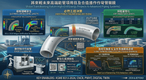
隨著 2026 年 ASME B31J 的全面強制導入,管線應力與柔性分析已完成從經驗公式向有限元素分析(FEA)的歷史性過渡。然而,規範的演進並未止步於此。展望未來,ASME B31J 及其相關標準的更新版計畫,正朝向全數位化、高精度預測模型以及與前沿製造技術深度整合的方向發展。With the full, mandatory implementation of ASME B31J in 2026, piping stress and flexibility analysis has completed a historic transition from empirical formulas to Finite Element Analysis (FEA). However, the evolution of the code does not stop here. Looking to the future, the update plans for ASME B31J and its related standards are trending towards full digitalization, high-precision predictive models, and deep integration with frontier manufacturing technologies.
9.1 全數位化與雲端 API 數據整合 / 9.1 Full Digitalization and Cloud API Data Integration
傳統的管線設計高度仰賴工程師手動查閱規範圖表。未來的 B31J 演進將進一步推動「規範數據服務化(Code Data Service)」。透過雲端運算與 API 技術,B31J 的最新應力強化係數與柔性因子將能即時、動態地與主流應力分析軟體(如 CAESAR II, AutoPIPE)進行深度串接67。這種全數位化的無縫接軌,不僅消除了人為查表的延遲與誤差,更允許針對非標準、特殊幾何形狀的管件,透過雲端即時呼叫標準化的 FEA 演算法,瞬間生成專屬的 SIF 數值,顯著提升了配管應力分析的靈活性與精確度7。Traditional piping design relies heavily on engineers manually looking up code charts. The future evolution of B31J will further promote “Code Data Service.” Through cloud computing and API technologies, the latest B31J SIFs and flexibility factors will be able to interface deeply, dynamically, and in real-time with mainstream stress analysis software (such as CAESAR II, AutoPIPE)67. This seamless, fully digital connection not only eliminates the delays and errors of manual look-ups but also allows for non-standard, specially geometrically shaped components to instantly generate bespoke SIF values by calling upon standardized FEA algorithms via the cloud, remarkably enhancing the flexibility and accuracy of piping stress analysis7.
9.2 基於數位孿生 (Digital Twin) 的高精度生命週期分析 / 9.2 High-Precision Life-Cycle Analysis Based on Digital Twins (DT)
B31J 對三維受力狀態的精確解耦,為建立高能管線的「數位孿生(Digital Twin, DT)」奠定了完美的物理與數學基礎。未來的工程實務將不再侷限於建廠前的靜態設計,而是將 B31J 的高精度 FEA 數據庫與現場感測器(溫度、振動、應變規)結合,打造出能與實體管線即時互動的虛擬系統69。這種「系統級數位孿生(System DTs)」能動態模擬 3D/5D 冷作彎管在長期汽水兩相流衝擊下的微觀應力變化,並利用機器學習(Machine Learning, ML)演算法預測疲勞裂紋的萌生與流體加速腐蝕(FAC)的確切位置,從而實現從「預防性維護」邁向「預測性維護(Predictive Maintenance)」的智慧轉型70。B31J’s precise decoupling of three-dimensional stress states lays a perfect physical and mathematical foundation for building “Digital Twins (DT)” of high-energy piping. Future engineering practices will no longer be confined to static pre-construction designs; instead, they will merge B31J’s high-precision FEA databases with on-site sensors (temperature, vibration, strain gauges) to create virtual systems capable of real-time interaction with physical pipelines69. These “System DTs” can dynamically simulate the micro-stress variations of 3D/5D cold bends under the long-term impact of steam-water two-phase flows, and employ Machine Learning (ML) algorithms to predict the exact initiation locations of fatigue cracks and Flow-Accelerated Corrosion (FAC). This achieves a smart transformation from “preventive maintenance” to “Predictive Maintenance”70.
9.3 前沿製造技術 (積層製造與智慧熱處理) 之合規性對接 / 9.3 Compliance Interfacing with Frontier Manufacturing Technologies (Additive Manufacturing and Smart Heat Treatment)
隨著工業 4.0 的推進,管線元件的製造正經歷顛覆。未來 B31J 的擴充藍圖,預期將整合積層製造(Additive Manufacturing, AM)等前沿工法所產出之管件的應力評估基準69。對於冷作彎管工法而言,機器學習與貝氏最佳化(Bayesian Optimization)演算法將被導入數控彎管與 IH-PBHT 感應熱處理製程中。透過建立「製程數位孿生(Process DTs)」,製造端能即時監控彎管各區段的溫度分佈與應變歷史,並即時回饋修正加熱參數,確保材料微觀組織(如 316L 的奧氏體穩定性或 A106 的晶格回復)完美達到法規要求73。這種「製造數據與 B31J 應力模型」的閉環整合,將使潁璋工程所提倡的「三合一工法」發揮出更極致的潛力,確保每一件產出的冷作彎管在虛擬模型與實體運作中皆具備絕對的可靠度。With the advancement of Industry 4.0, the manufacturing of piping components is undergoing a disruption. The future expansion blueprint for B31J is expected to integrate stress evaluation benchmarks for components produced by frontier methods such as Additive Manufacturing (AM)69. For the cold bending process, machine learning and Bayesian Optimization algorithms will be introduced into CNC bending and IH-PBHT induction heat treatment processes. By establishing “Process DTs,” the manufacturing end can monitor the temperature distribution and strain history of each section of the bend in real-time, instantly feeding back corrections to heating parameters to ensure that material microstructures (e.g., the austenite stability of 316L or the lattice recovery of A106) perfectly meet regulatory requirements73. This closed-loop integration of “manufacturing data and B31J stress models” will allow the “Three-in-One Method” promoted by Ying-Zhang Engineering to realize its most extreme potential, ensuring that every produced cold bend possesses absolute reliability in both virtual models and physical operations.
十、結論 / 10. Conclusions
綜上所述,基於 2026 年最新版 ASME B31J 規範的嚴謹深度解析,並結合微觀冶金學、三維流體動力學與全生命週期技術經濟學的交叉驗證,本研究針對 CCPP 工廠採用 ASTM A106 碳鋼大半徑冷作彎管取代傳統 1.5D 彎頭之差異化與優勢,歸納出以下核心結論:In summary, based on the rigorous in-depth analysis of the latest 2026 edition of the ASME B31J code, and combining cross-validations in micro-metallurgy, 3D fluid dynamics, and life-cycle techno-economics, this study outlines the following core conclusions regarding the differentiation and advantages of replacing traditional 1.5D elbows with ASTM A106 carbon steel large-radius cold bends in CCPP plants:
- 規範演進與力學精確化解耦:ASME B31J-2026 徹底摒棄了傳統附錄D 單一且極端保守的經驗法則。透過柔性特徵參數 h 的精確推導,大半徑(3D/5D)冷作彎管在面內、面外與扭轉方向的應力強化係數被科學證實,其數值已幾乎完全退化至理想直管的絕對下限(1.0)。這大幅解除了傳統設計對彎頭應力集中的恐懼,為管線佈局提供了前所未有的安全裕度。Code Evolution and Precise Mechanical Decoupling: ASME B31J-2026 completely discards the singular and extremely conservative empirical rules of traditional Appendix D. Through precise derivation of the flexibility characteristic parameter h, it is scientifically proven that the Stress Intensification Factors (SIF) of large-radius (3D/5D) cold bends in the in-plane, out-of-plane, and torsional directions have nearly fully degenerated to the absolute lower limit of an ideal straight pipe (1.0). This dramatically dispels the traditional design fears regarding stress concentration at elbows, offering unprecedented safety margins for piping layouts.
- 流固耦合與 FAC 抑制的氣動力學突破:5D 大半徑彎管憑藉平緩的曲率過渡,徹底消除了1.5D 彎頭內弧側致命的邊界層分離與強烈逆壓梯度。平穩均勻的流線分佈不僅降低了流體壓降能耗,更使得管壁的保護性磁鐵礦層得以穩定存在,從流體力學與化學腐蝕的根源上解決了 CCPP 高能兩相流管線中破壞力最強的流體加速腐蝕(FAC)問題。Aerodynamic Breakthroughs in Fluid-Solid Coupling and FAC Suppression: Utilizing gentle curvature transitions, 5D large-radius bends completely eliminate the fatal boundary layer separation and intense adverse pressure gradients on the intrados of 1.5D elbows. The steady, uniform streamline distribution not only reduces fluid pressure drop energy consumption but also allows the protective magnetite layer on the pipe wall to exist stably, resolving the most destructive Flow-Accelerated Corrosion (FAC) problems in CCPP high-energy two-phase pipelines from the very roots of fluid mechanics and chemical corrosion.
- 利害關係人價值最大化與「能彎不銲」實踐:從業主的維護成本到 EPC 的空間配置,大半徑冷作彎管展現了壓倒性的全生命週期優勢。潁璋工程提出的「三合一工法」(CNC冷彎 + IH-PBHT + 雲端履歷),完美實踐了「能彎不銲」的核心理念,消除了高風險漸變銲道,並大幅降低對設備的端點推力。Maximization of Stakeholder Value and “Bend over Weld” Practice: From owners’ maintenance costs to EPC spatial configurations, large-radius cold bends demonstrate an overwhelming life-cycle advantage. The “Three-in-One Method” (CNC Cold Bending + IH-PBHT + Cloud Traceability) proposed by Ying-Zhang Engineering perfectly practices the core concept of “Bend over Weld,” eliminating high-risk geometric transition welds and massively reducing end-point thrusts on equipment.
- 精準對接 5%~20% 應變率之法規放寬與冶金控制:針對 3D/5D 彎管落在 5%~20% 區間的成型應變率,IH-PBHT(感應加熱彎後熱處理)技術展現了極佳的適用性。它不僅滿足 ASME B31.1 / B31.3 對於成型應變熱處理的法規要求,更能以極低的變形風險與耗能,精準釋放碳鋼與合金鋼的冷作殘留應力,確保高溫潛變工況下的長期斷裂韌性與結構安全。Precise Interfacing with Code Relaxations for 5%~20% Strain Rates and Metallurgical Control: Targeting the forming strain rate of 3D/5D bends falling in the 5%~20% interval, IH-PBHT (Induction Heating Post-Bend Heat Treatment) technology shows excellent applicability. It not only meets the ASME B31.1 / B31.3 regulatory requirements for forming strain heat treatments but can also precisely release cold-working residual stresses in carbon and alloy steels with extremely low deformation risks and energy consumption, ensuring long-term fracture toughness and structural safety under high-temperature creep conditions.
- 引領未來的全數位化與數位孿生佈局:2026 年後的 ASME B31J 將不再僅是一本靜態規範,其奠基於 FEA 的核心將與雲端運算、數位孿生及機器學習深度融合。透過即時的製程監控與高精度生命週期預測,「三合一工法」產出的冷作彎管將完美對接未來的智慧發電與能源網路需求。Leading the Future Layout of Full Digitalization and Digital Twins: Post-2026, ASME B31J will no longer be merely a static code; its FEA-founded core will merge deeply with cloud computing, digital twins, and machine learning. Through real-time process monitoring and high-precision life-cycle predictions, the cold bends produced by the “Three-in-One Method” will flawlessly interface with the demands of future smart power generation and energy networks.
放眼未來的高階發電與能源運輸工程,全面過渡至基於 ASME B31J-2026 科學驗證架構下的大半徑數控冷作彎管,並輔以精確的局部感應熱處理與數位化追溯技術,將不再是成本考量下的替代方案,而是追求現代複循環機組與 LNG 儲運設施極致運轉安全、效能最佳化與長效可靠度之必然工程決策。Looking toward the future of high-end power generation and energy transportation engineering, a comprehensive transition to CNC large-radius cold bends based on the scientifically validated framework of ASME B31J-2026, supplemented by precise localized induction heat treatment and digital traceability technologies, will no longer be an alternative solution driven by cost considerations. Instead, it is an inevitable engineering decision in the pursuit of extreme operational safety, efficiency optimization, and long-term reliability for modern combined cycle units and LNG storage/transport facilities.
參考文獻 / References
- 現代電廠高能管線(1.5D vs. 5D 彎管)之全方位最佳化設計:流體, https://yz-pipe-bending.com.tw/%E7%8F%BE%E4%BB%A3%E9%9B%BB%E5%BB%A0%E9%AB%98%E8%83%BD%E7%AE%A1%E7%B7%9A%EF%BC%881-5d-vs-5d-%E5%BD%8E%E7%AE%A1%EF%BC%89%E4%B9%8B%E5%85%A8%E6%96%B9%E4%BD%8D%E6%9C%80%E4%BD%B3%E5%8C%96%E8%A8%AD/
- 針對CCPP汽水兩相流管路中1.5D至5D彎管曲率半徑優化配置與抗沖, https://yz-pipe-bending.com.tw/%E9%87%9D%E5%B0%8Dccpp%E6%B1%BD%E6%B0%B4%E5%85%A9%E7%9B%B8%E6%B5%81%E7%AE%A1%E8%B7%AF%E4%B8%AD1-5d%E8%87%B35d%E5%BD%8E%E7%AE%A1%E6%9B%B2%E7%8E%87%E5%8D%8A%E5%BE%91%E5%84%AA%E5%8C%96%E9%85%8D%E7%BD%AE/
- 基於2026 ASME B31J 規範之大型CCPP 專案管線工法優化, https://yz-pipe-bending.com.tw/%E5%9F%BA%E6%96%BC-2026-asme-b31j-%E8%A6%8F%E7%AF%84%E4%B9%8B%E5%A4%A7%E5%9E%8B-ccpp-%E5%B0%88%E6%A1%88%E7%AE%A1%E7%B7%9A%E5%B7%A5%E6%B3%95%E5%84%AA%E5%8C%96%EF%BC%9Aepc-%E4%BB%8B%E9%9D%A2%E5%8D%94/
- 基於ASME B31J與流固耦合分析之CCPP高能管線(P91/P92)流體加速, https://yz-pipe-bending.com.tw/%E5%9F%BA%E6%96%BCasme-b31j%E8%88%87%E6%B5%81%E5%9B%BA%E8%80%A6%E5%90%88%E5%88%86%E6%9E%90%E4%B9%8Bccpp%E9%AB%98%E8%83%BD%E7%AE%A1%E7%B7%9Ap91-p92%E6%B5%81%E9%AB%94%E5%8A%A0%E9%80%9F%E8%85%90/
- 潁璋重型彎管工程- 興達電廠照片資料來源:https://www.ctee.com.tw, https://www.facebook.com/100057434619150/photos/%E8%88%88%E9%81%94%E9%9B%BB%E5%BB%A0%E7%85%A7%E7%89%87%E8%B3%87%E6%96%99%E4%BE%86%E6%BA%90httpswwwcteecomtwnews20250707700749-431202fbclidiwy2xjawmkvczlehrua2fl/1265058835418592/
- 針對ASME 2026 規範下317L、317LN 與317LMN 管線運用於通霄, https://yz-pipe-bending.com.tw/%E9%87%9D%E5%B0%8D-asme-2026-%E8%A6%8F%E7%AF%84%E4%B8%8B-317l%E3%80%81317ln-%E8%88%87-317lmn-%E7%AE%A1%E7%B7%9A%E9%81%8B%E7%94%A8%E6%96%BC%E9%80%9A%E9%9C%84%E9%9B%BB%E5%BB%A0-2-%E6%9C%9F%E6%9B%B4/
- Stress Intensity Factor (SIF), Flexibility Factor: ASME B31.3 vs ASME, https://whatispiping.com/stress-intensity-factor-sif-flexibility-factor-asme-b-31j/
- Mastering ASME B31J Piping Stress Analysis for Plant Integrity, https://epcland.com/asme-b31j-piping-stress-analysis/
- pdf – NASA Technical Reports Server (NTRS), https://ntrs.nasa.gov/api/citations/19680021106/downloads/19680021106.pdf
- Usas B31 – 7 1969 – Ocr | PDF | Boiler | Stress (Mechanics) – Scribd, https://www.scribd.com/document/669353025/USAS-B31-7-1969-OCR
- Stress Intensity Factor (SIF) For Special Geometries in Piping Stress, https://cadeengineering.com/study-case/stress-intensity-factor-sif-for-special-geometries-in-piping-stress-analyisis/
- ASME B31J-2023 Overview: Stress Intensification Factor (SIF) and, https://fengshecad.com/795/
- 2026版ASME B31J 強制導入下高能管線工程之典範轉移:基於B31.1, https://yz-pipe-bending.com.tw/2026%E7%89%88-asme-b31j-%E5%BC%B7%E5%88%B6%E5%B0%8E%E5%85%A5%E4%B8%8B%E9%AB%98%E8%83%BD%E7%AE%A1%E7%B7%9A%E5%B7%A5%E7%A8%8B%E4%B9%8B%E5%85%B8%E7%AF%84%E8%BD%89%E7%A7%BB%EF%BC%9A%E5%9F%BA%E6%96%BC-b31/
- Understanding SIF for Piping Elbows | PDF | Stress (Mechanics), https://www.scribd.com/document/961304255/Pipe-ELbow-SIF
- Piping Elbow or Bend SIF (Stress Intensification Factor), https://whatispiping.com/bend-sif/
- Alignment of Stress Intensification and Flexibility Factors for the B31, https://asmedigitalcollection.asme.org/HTTPHandlers/ArticlePdfHandler.ashx?journal=PVP2012&multimediaId=4436288
- 基於2026 ASME B31J 規範之CCPP 高能管線銲接彎頭與3D/5D 冷作, https://yz-pipe-bending.com.tw/%E5%9F%BA%E6%96%BC-2026-asme-b31j-%E8%A6%8F%E7%AF%84%E4%B9%8B-ccpp-%E9%AB%98%E8%83%BD%E7%AE%A1%E7%B7%9A%E9%8A%B2%E6%8E%A5%E5%BD%8E%E9%A0%AD%E8%88%87-3d-5d-%E5%86%B7%E4%BD%9C%E5%BD%8E%E7%AE%A1%E7%B5%90/
- Definition of Terms (ASME B31J), https://docs.bentley.com/LiveContent/web/AutoPIPE-v2026.0.1/Help/en/Topics/Codes/ASME-B31J_code_definition_of_termsj.html
- Stress intensification factor, sustained stress index and flexibility, https://www.researchgate.net/publication/343479473_Stress_intensification_factor_sustained_stress_index_and_flexibility_factor_analysis_of_large_DT_elbows
- Stress Intensification & Flexibility Factor Calculator (B31.3 Appendix D), https://pipingtoolset.com/calculators/b313-stress-intensification-factors/
- Understanding Black Steel Pipes vs Carbon Steel Pipes in Piping, https://epcland.com/black-steel-pipes-vs-carbon-steel-pipes/
- CCPP電廠P9x高能管線曲率半徑(1.5D規格品銲接彎頭與3D/5D冷作, https://yz-pipe-bending.com.tw/ccpp%E9%9B%BB%E5%BB%A0p9x%E9%AB%98%E8%83%BD%E7%AE%A1%E7%B7%9A%E6%9B%B2%E7%8E%87%E5%8D%8A%E5%BE%91%EF%BC%881-5d%E8%A6%8F%E6%A0%BC%E5%93%81%E9%8A%B2%E6%8E%A5%E5%BD%8E%E9%A0%AD%E8%88%873d-5d%E5%86%B7/
- MP14-Confidential-RCFA-FINAL-April-21-2023-Redacted.pdf, https://www.phmsa.dot.gov/sites/phmsa.dot.gov/files/2023-05/MP14-Confidential-RCFA-FINAL-April-21-2023-Redacted.pdf
- ASME B31.1-2024 Stress Intensification Factors (SIFs) — FAQ, https://pipingtoolset.com/faq/b311-stress-intensification-factors/
- CAEPIPE Code Compliance Manual – Wayplant, https://wayplant.com/wp-content/uploads/2022/06/CAEPIPE_Code_Compliance_Manual.pdf
- Welding Tee SIF Calculator — B31.3 App. D, 2018 & Earlier, https://pipingtoolset.com/calculators/welding-tee-sif/
- ASTM A106 Grade B Pipe: Grades, Properties and Selection, https://www.gneesteels.com/info/astm-a106-grade-b-pipe-79483472.html
- ASTM A106 Gr.B & Gr.C Seamless Pipe — Procurement Guide for, https://www.slpipeline.com/astm-a106-grade-b-and-grade-c-seamless-pipe.html
- 1 Power Piping: Question of using ASTM A106 Grade B | Eng-Tips, https://www.eng-tips.com/threads/b31-1-power-piping-question-of-using-astm-a106-grade-b.280455/
- ASME B31.3 Process Piping – AquaEnergy Expo Knowledge Hub, https://kh.aquaenergyexpo.com/wp-content/uploads/2025/02/ASME-B31.3-Process-Piping.pdf
- ASTM A106 Grade B Specification Comprehensive Analysis, https://pandapipe.com/blog/astm-a106-grade-b-specification/
- A106 Stdandard | PDF | Pipe (Fluid Conveyance) | Welding – Scribd, https://www.scribd.com/document/1057322056/A106-stdandard
- A106 Grade B Carbon Steel Pipes | PDF – Scribd, https://www.scribd.com/document/1057333653/A106-Grade-B-Carbon-Steel-Pipes
- Carbon Steel Pipes – Pressure and Temperature Ratings, Imperial, https://www.engineeringtoolbox.com/a106-carbon-steel-pipes-d_370.html
- ASME B31.1 與ASME B31.3 感應熱彎退應力熱處理(SRHT)差異化, https://yz-pipe-bending.com.tw/asme-b31-1-%E8%88%87-asme-b31-3-%E6%84%9F%E6%87%89%E7%86%B1%E5%BD%8E%E5%BE%8C%E9%80%80%E6%87%89%E5%8A%9B%E7%86%B1%E8%99%95%E7%90%86srht%E5%B7%AE%E7%95%B0%E5%8C%96%E5%88%86%E6%9E%90%E7%A0%94%E7%A9%B6/
- ASME B31.1 動力配管規範下3≦ R/D ≦5 冷作彎管的設計、製造, https://yz-pipe-bending.com.tw/asme-b31-1-%E5%8B%95%E5%8A%9B%E9%85%8D%E7%AE%A1%E8%A6%8F%E7%AF%84%E4%B8%8B-3%E2%89%A6-r-d-%E2%89%A65-%E5%86%B7%E4%BD%9C%E5%BD%8E%E7%AE%A1%E7%9A%84%E8%A8%AD%E8%A8%88%E3%80%81%E8%A3%BD%E9%80%A0%E3%80%81/
- 基於2026 ASME B31.1 與B31J 規範之複循環發電廠動力管線3D/5D, https://yz-pipe-bending.com.tw/%E5%9F%BA%E6%96%BC-2026-asme-b31-1-%E8%88%87-b31j-%E8%A6%8F%E7%AF%84%E4%B9%8B%E8%A4%87%E5%BE%AA%E7%92%B0%E7%99%BC%E9%9B%BB%E5%BB%A0%E5%8B%95%E5%8A%9B%E7%AE%A1%E7%B7%9A-3d-5d-%E5%86%B7%E4%BD%9C/
- ASME B31.3 Process Piping Guide – LANL Engineering Standards, https://engstandards.lanl.gov/esm/pressure_safety/Section%20REF-3-R0.pdf
- 2026 ASME B31.1 與B31.3 壓力管線規範演進:從設計安全裕度到, https://yz-pipe-bending.com.tw/2026-asme-b31-1-%E8%88%87-b31-3-%E5%A3%93%E5%8A%9B%E7%AE%A1%E7%B7%9A%E8%A6%8F%E7%AF%84%E6%BC%94%E9%80%B2%EF%BC%9A%E5%BE%9E%E8%A8%AD%E8%A8%88%E5%AE%89%E5%85%A8%E8%A3%95%E5%BA%A6%E5%88%B0%E5%85%88/
- 新建或升級改造CCPP 機組採用冷作彎管工法於低壓濕蒸氣、冷再熱, https://yz-pipe-bending.com.tw/%E6%96%B0%E5%BB%BA%E6%88%96%E5%8D%87%E7%B4%9A%E6%94%B9%E9%80%A0-ccpp-%E6%A9%9F%E7%B5%84%E6%8E%A1%E7%94%A8%E5%86%B7%E4%BD%9C%E5%BD%8E%E7%AE%A1%E5%B7%A5%E6%B3%95%E6%96%BC%E4%BD%8E%E5%A3%93%E6%BF%95/
- Power Piping ASME Code for Pressure Piping, B31 – pdfcoffee.com, https://pdfcoffee.com/power-piping-asme-code-for-pressure-piping-b31-pdf-free.html
- ASME B31.1 – Future Energy Steel, https://energy-steel.com/wp-content/uploads/2025/03/ASME-B31.1.pdf
- ASME B31.1 Power Piping – Issuu, https://issuu.com/aungmyatkyaw9/docs/asme.b31.1.2014
- 5D電銲彎頭沖蝕現象綜合分析、退化機制與3D/5D冷作彎管系統化, https://yz-pipe-bending.com.tw/1-5d%E9%9B%BB%E9%8A%B2%E5%BD%8E%E9%A0%AD%E6%B2%96%E8%9D%95%E7%8F%BE%E8%B1%A1%E7%B6%9C%E5%90%88%E5%88%86%E6%9E%90%E3%80%81%E9%80%80%E5%8C%96%E6%A9%9F%E5%88%B6%E8%88%873d-5d%E5%86%B7%E4%BD%9C%E5%BD%8E/
- 「以彎代銲」取代傳統電銲彎頭於CCPP 高能管線之綜合效益評估, https://yz-pipe-bending.com.tw/%E3%80%8C%E4%BB%A5%E5%BD%8E%E4%BB%A3%E9%8A%B2%E3%80%8D%E5%8F%96%E4%BB%A3%E5%82%B3%E7%B5%B1%E9%9B%BB%E9%8A%B2%E5%BD%8E%E9%A0%AD%E6%96%BC-ccpp-%E9%AB%98%E8%83%BD%E7%AE%A1%E7%B7%9A%E4%B9%8B%E7%B6%9C/
- 現代高能動力管線「以彎代銲」之技術經濟評估:從傳統配管到大, https://yz-pipe-bending.com.tw/%E7%8F%BE%E4%BB%A3%E9%AB%98%E8%83%BD%E5%8B%95%E5%8A%9B%E7%AE%A1%E7%B7%9A%E3%80%8C%E4%BB%A5%E5%BD%8E%E4%BB%A3%E9%8A%B2%E3%80%8D%E4%B9%8B%E6%8A%80%E8%A1%93%E7%B6%93%E6%BF%9F%E8%A9%95%E4%BC%B0%EF%BC%9A/
- Piping Engineering Knowledge – SWBPIPE, https://swbpipe.com/reader/reading.html
- How to Design Pipe Expansion Loops for Piping Systems – EPCLand, https://epcland.com/pipe-expansion-loops/
- A Practical Specification Checklist for carbon steel elbow, https://www.czwhsteel.com/A-Practical-Specification-Checklist-for-carbon-steel-elbow-id05160735.html
- Pipe – ASHRAE – Greenville Chapter, https://ashrae4greenville.starchapter.com/images/downloads/2021_Newsletters/presentation_flexjoints.pdf
- Mechanical and Electrical Design of Pump Stations, https://www.publications.usace.army.mil/Portals/76/Users/182/86/2486/EM1110-2%20-3105.pdf
- 潁璋重型彎管工程- 滴佳啦… – Facebook, https://m.facebook.com/100057434619150/photos/649046497019832/
- CCPP主蒸汽高能管線之支管線(4吋含以下)在熱應力循環下之失效, https://yz-pipe-bending.com.tw/ccpp%E4%B8%BB%E8%92%B8%E6%B1%BD%E9%AB%98%E8%83%BD%E7%AE%A1%E7%B7%9A%E4%B9%8B%E6%94%AF%E7%AE%A1%E7%B7%9A4%E5%90%8B%E5%90%AB%E4%BB%A5%E4%B8%8B%E5%9C%A8%E7%86%B1%E6%87%89%E5%8A%9B%E5%BE%AA%E7%92%B0/
- 潁璋工程興業有限公司– 冷作彎管, https://yz-pipe-bending.com.tw/
- ASME B31.3 PWHT Requirements Overview | PDF | Welding – Scribd, https://www.scribd.com/document/245366047/Heat-Treatment-requirement-as-per-ASME-B31-3
- PWHT Soak Time Calculator — Post Weld Heat Treatment Code, https://www.weldfabworld.com/pwht-soak-time-calculator/
- 2026 ASME 規範架構下B31.1 & B31.3 成型應變率之深度剖析, https://yz-pipe-bending.com.tw/2026-asme-%E8%A6%8F%E7%AF%84%E6%9E%B6%E6%A7%8B%E4%B8%8B-b31-1-b31-3-%E6%88%90%E5%9E%8B%E6%87%89%E8%AE%8A%E7%8E%87%E4%B9%8B%E6%B7%B1%E5%BA%A6%E5%89%96%E6%9E%90%EF%BC%9A5d-%E5%86%B7%E4%BD%9C%E5%BD%8E/
- 解析2026 ASME B31.1與B31J應變率(5%~20%)放寬與IH-PBHT適用, https://yz-pipe-bending.com.tw/%E8%A7%A3%E6%9E%902026-asme-b31-1%E8%88%87b31j%E6%87%89%E8%AE%8A%E7%8E%87520%E6%94%BE%E5%AF%AC%E8%88%87ih-pbht%E9%81%A9%E7%94%A8%EF%BC%9A%E6%BD%81%E7%92%8B%E5%B7%A5%E7%A8%8B%E5%B0%8D%E6%96%BCp9x/
- 2026 ASME 規範下B31.1 動力管線施工工法之深度剖析, https://yz-pipe-bending.com.tw/2026-asme-%E8%A6%8F%E7%AF%84%E4%B8%8B-b31-1-%E5%8B%95%E5%8A%9B%E7%AE%A1%E7%B7%9A%E6%96%BD%E5%B7%A5%E5%B7%A5%E6%B3%95%E4%B9%8B%E6%B7%B1%E5%BA%A6%E5%89%96%E6%9E%90%EF%BC%9A5d-%E5%86%B7%E4%BD%9C%E5%BD%8E/
- 2026 ASME B31J 演算法框架下P91/P92 5D 冷作彎管之幾何力學, https://yz-pipe-bending.com.tw/2026-asme-b31j-%E6%BC%94%E7%AE%97%E6%B3%95%E6%A1%86%E6%9E%B6%E4%B8%8B-p91-p92-5d-%E5%86%B7%E4%BD%9C%E5%BD%8E%E7%AE%A1%E4%B9%8B%E5%B9%BE%E4%BD%95%E5%8A%9B%E5%AD%B8%E3%80%81%E6%BD%9B%E8%AE%8A%E9%80%80/
- ASME B31.1/B31J 動力管線成型機制與冶金策略演進:P91 熱彎急冷, https://yz-pipe-bending.com.tw/asme-b31-1-b31j-%E5%8B%95%E5%8A%9B%E7%AE%A1%E7%B7%9A%E6%88%90%E5%9E%8B%E6%A9%9F%E5%88%B6%E8%88%87%E5%86%B6%E9%87%91%E7%AD%96%E7%95%A5%E6%BC%94%E9%80%B2%EF%BC%9Ap91-%E7%86%B1%E5%BD%8E%E6%80%A5%E5%86%B7/
- 2026 ASME B31.1 動力配管合規策略與先進製造整合分析報告:針對, https://yz-pipe-bending.com.tw/2026-asme-b31-1-%E5%8B%95%E5%8A%9B%E9%85%8D%E7%AE%A1%E5%90%88%E8%A6%8F%E7%AD%96%E7%95%A5%E8%88%87%E5%85%88%E9%80%B2%E8%A3%BD%E9%80%A0%E6%95%B4%E5%90%88%E5%88%86%E6%9E%90%E5%A0%B1%E5%91%8A%EF%BC%9A/
- ASME B31.3 Process Piping — The Complete Engineer’s Guide, https://www.weldfabworld.com/asme-b31-3-process-piping/
- https://yz-pipe-bending.com.tw/%E6%B6%B2%E5%8C%96%E5%A4%A9%E7%84%B6%E6%B0%A3%EF%BC%88lng%EF%BC%89%E5%9F%BA%E7%A4%8E%E8%A8%AD%E6%96%BD%E4%BD%8E%E6%BA%AB%E8%BC%B8%E9%80%81%E7%AE%A1%E7%B7%9A%E7%B3%BB%E7%B5%B1%E5%86%B7%E4%BD%9C/
- Cryogenic mechanical properties and tribological behaviors of AISI, https://www.researchgate.net/publication/390098081_Cryogenic_mechanical_properties_and_tribological_behaviors_of_AISI_stainless_316L_steel_cooled_by_liquid_nitrogen
- The Effects of Electrochemical Hydrogen Charging on Charpy, https://www.mdpi.com/2073-4352/13/8/1249
- ASME B31J Essentials for Piping Analysis | PDF – Scribd, https://www.scribd.com/document/961302630/B31J-Essentials
- ASME B31J: I & K Factors in Pipe Analysis, https://www.cortexsoftware.com.au/blog/understanding-asme-b31j-methods-i-factors-and-k-factors-in-piping-stress-analysis
- (PDF) Digital Twins for Additive Manufacturing: A State-of-the-Art, https://www.researchgate.net/publication/347158165_Digital_Twins_for_Additive_Manufacturing_A_State-of-the-Art_Review
- Digital Twins in Additive Manufacturing: A Systematic Review, https://www.researchgate.net/publication/383701641_Digital_Twins_in_Additive_Manufacturing_A_Systematic_Review
- (PDF) Digital twins in additive manufacturing – ResearchGate, https://www.researchgate.net/publication/391967328_Digital_twins_in_additive_manufacturing
- (PDF) A digital twin hierarchy for metal additive manufacturing, https://www.researchgate.net/publication/360109986_A_digital_twin_hierarchy_for_metal_additive_manufacturing
- (PDF) Towards a digital twin framework in additive manufacturing, https://www.researchgate.net/publication/380390148_Towards_a_digital_twin_framework_in_additive_manufacturing_Machine_learning_and_bayesian_optimization_for_time_series_process_optimization
- (PDF) Digital Twins and Additive Manufacturing – ResearchGate, https://www.researchgate.net/publication/365584788_Digital_Twins_and_Additive_Manufacturing