
一、 緒論 / 1. Introduction
在全球能源轉型的宏觀戰略驅動下,燃氣複循環發電廠(Combined Cycle Power Plant, CCPP)憑藉其卓越的熱力學轉換效率、顯著降低的碳排放量,以及具備快速起停(Fast Start-Stop)的電網調峰彈性,已迅速躍升為現代電力結構中的基載與中載發電主力。為了持續突破熱力學卡諾循環的效率極限,現代 CCPP 系統中的高能動力管線(High-Energy Piping, HEP)——包含主蒸汽(Main Steam)與高溫再熱蒸汽(Hot Reheat)管線——其設計操作溫度已常態性地跨越 600°C 門檻,內部流體操作壓力更動輒高達 25 至 35 MPa 以上1。 Driven by the macro-strategy of global energy transition, Combined Cycle Power Plants (CCPP) have rapidly emerged as the primary base-load and intermediate-load pillars in modern power grids, owing to their exceptional thermodynamic conversion efficiency, significantly reduced carbon emissions, and agile peak-shaving capabilities (fast start-stop). To continuously push the efficiency limits of the thermodynamic Carnot cycle, the design operating temperatures of High-Energy Piping (HEP) systems in modern CCPPs—including Main Steam and Hot Reheat lines—now routinely exceed the 600°C threshold, with internal fluid operating pressures frequently reaching 25 to 35 MPa and above1.
在如此極端的熱力學與流體力學交錯服役條件下,傳統的低合金鋼材料(如 P22,12Cr-1Mo 鋼)已面臨其材料潛變強度的物理極限。當操作溫度超過 620°C 時,傳統材料的最大容許應力甚至會驟降至 50 MPa 以下;這迫使工程界全面轉向採用潛變強度增強型肥粒鐵鋼(Creep Strength Enhanced Ferritic Steels, CSEF),其中業界最廣泛應用的標準材質即為 P9x 系列(如 ASTM A335 P91、P92 等)3。 Under such extreme and intersecting thermodynamic and fluid dynamic service conditions, traditional low-alloy steels (such as P22, 12Cr-1Mo steel) have reached the physical limits of their material creep strength. When operating temperatures exceed 620°C, the maximum allowable stress of traditional materials plummets to below 50 MPa. This has forced the engineering sector to pivot entirely toward Creep Strength Enhanced Ferritic Steels (CSEF), with the P9x series (e.g., ASTM A335 P91, P92) being the most widely adopted standard materials in the industry3.
P91 與 P92 鋼卓越的潛變抗力,源自於其極度複雜且對熱循環高度敏感的微觀冶金組織。在出廠前,這些管材必須經過嚴密的正常化與回火(Normalizing and Tempering, N&T)程序,藉此塑造出富含高密度差排(Dislocations)的回火麻田散鐵(Tempered Martensite)基體,並輔以精確析出的奈米級碳氮化物來鎖死晶界滑移4。然而,在 CCPP 建廠實務中,廠區管線佈局不可避免地需要大量的轉向幾何設計。過去數十年間,管線工程界習慣沿用傳統的 1.5D 短半徑電銲彎頭(Welded Elbow)配合直管進行現場銲接拼裝。當這種極度依賴完美微觀組織的 CSEF 管材,遭遇現場高空管架(Pipe Rack)的侷限空間、難以預測的極端天候,以及容錯率實質為零的四階段銲接熱處理循環(包含強制預熱、氫烘烤、降溫相變、與嚴格控溫的銲後熱處理)時,傳統 1.5D 銲接彎頭的幾何劣勢與冶金缺陷便會被無限放大。 The exceptional creep resistance of P91 and P92 steels stems from their highly complex and thermally sensitive microstructural metallurgy. Prior to leaving the mill, these pipes undergo rigorous Normalizing and Tempering (N&T) procedures to form a Tempered Martensite matrix rich in high-density dislocations, supplemented by precisely precipitated nano-scale carbonitrides that lock grain boundary sliding4. However, in practical CCPP construction, plant piping layouts inevitably require numerous directional geometric designs. For decades, the piping engineering industry has habitually utilized traditional 1.5D short-radius welded elbows combined with straight pipes for field welding and assembly. When these CSEF materials—which rely heavily on a pristine microstructure—are subjected to the confined spaces of high-altitude pipe racks, unpredictable extreme weather, and a virtually zero-fault-tolerance four-stage welding heat treatment cycle (mandatory preheating, hydrogen bake-out, phase transformation cooling, and strictly controlled post-weld heat treatment), the geometric disadvantages and metallurgical defects of traditional 1.5D welded elbows are exponentially magnified.
本研究報告旨在透過跨領域的深度剖析,整合物理冶金學、熱力學傳熱機制、固體應力分析(依據最新 ASME B31J 規範)以及流體動力學,全面探討 CCPP 現場環境下採用傳統 1.5D P9x 銲接彎頭所衍生的實務挑戰。透過解析第四型潛變裂紋(Type IV Cracking)的微觀萌生機制,對比感應加熱與電阻加熱的物理差異,並導入最新版規範與實務工法,本報告將論證為何在現代高能管線佈局中,捨棄現場 1.5D 銲接彎頭並全面過渡至廠內預製的冷作/熱作彎管,已成為確保電廠長期營運可靠度不可逆轉的技術演進方向。This research report aims to provide a cross-disciplinary, in-depth analysis integrating physical metallurgy, thermodynamic heat transfer mechanisms, solid stress analysis (based on the latest ASME B31J code), and fluid dynamics to comprehensively explore the practical challenges of employing traditional 1.5D P9x welded elbows in CCPP field environments. By dissecting the microstructural initiation mechanisms of Type IV Cracking, contrasting the physical differences between induction and resistance heating, and introducing the latest code revisions and practical fabrication methods, this report will demonstrate why abandoning field-welded 1.5D elbows in favor of shop-prefabricated cold/hot bends for modern high-energy piping layouts has become an irreversible technological evolution essential for ensuring long-term power plant operational reliability.
二、 P9x 潛變強度增強型鋼之冶金特性與微觀損傷機制 / 2. Metallurgical Characteristics and Micro-Damage Mechanisms of P9x Creep Strength Enhanced Ferritic Steels
要深刻理解 P9x 材料在現場銲接所遭遇的挑戰,必須先從其原子的晶格排列與合金元素的微觀交互作用著手。P91(X10CrMoVNb9-1)等材料之所以能承受 600°C 以上的高溫高壓,並非單純依賴合金固溶強化,而是建構在一個處於亞穩狀態的複雜多相組織之上。To deeply understand the challenges P9x materials face during field welding, one must first examine their atomic lattice arrangements and the micro-interactions of alloying elements. The reason materials like P91 (X10CrMoVNb9-1) can withstand high temperatures and pressures above 600°C relies not merely on solid solution strengthening, but rather on a complex multiphase microstructure maintained in a metastable state.
2.1 微觀組織強化機制與化學成分控制 / 2.1 Microstructural Strengthening Mechanisms and Chemical Composition Control
P91 材料的化學設計核心,是在 9% 鉻(Cr)與 1% 鉬(Mo)的基礎上,精準引入釩(V)、鈮(Nb)與控制比例的氮(N)進行微合金化2。為確保材料在冷卻過程中能生成理想的麻田散鐵微觀組織,其化學成分必須依循經過修正的鉻鎳平衡(Chromium-Nickel Balance, CNB)方程式嚴格調控,任何微量元素的偏差皆可能導致破壞性的肥粒鐵或殘留沃斯田鐵(Retained Austenite)生成6。 The core chemical design of P91 material is based on 9% Chromium (Cr) and 1% Molybdenum (Mo), precisely micro-alloyed with Vanadium (V), Niobium (Nb), and a controlled proportion of Nitrogen (N) 2. To ensure the material forms an ideal martensitic microstructure during cooling, its chemical composition must be strictly regulated according to a modified Chromium-Nickel Balance (CNB) equation; any deviation in trace elements can lead to the formation of destructive ferrite or retained austenite6.
P91 鋼的高溫潛變抗力由兩個主要析出相陣營負責捍衛。首先是富含鉻與鉬的 M23C6 碳化物,這類析出物主要沿著原沃斯田鐵晶界(Prior Austenite Grain Boundaries, PAGB)以及麻田散鐵板條(Lath)與區塊邊界成核析出;它們在巨觀上如同微觀的護城河,強烈抑制了高溫服役期間晶界的滑移與次晶粒的粗化。其次是富含釩與鈮的 MX 型碳氮化物(如 NbC, VN),這類析出相尺寸極小且均勻散佈於麻田散鐵基體內部,透過齊納釘扎效應(Zener Pinning Effect)鎖死基體內的高密度差排網路2。這種次晶界網路與細小析出相的共存,正是 P91 具備優異潛變強度的根本原因。 The high-temperature creep resistance of P91 steel is defended by two primary camps of precipitate phases. The first is chromium- and molybdenum-rich M23C6 carbides, which primarily nucleate and precipitate along Prior Austenite Grain Boundaries (PAGB) as well as martensitic lath and block boundaries. Macroscopically, they act like microscopic moats, strongly suppressing grain boundary sliding and sub-grain coarsening during high-temperature service. The second is vanadium- and niobium-rich MX-type carbonitrides (such as NbC, VN). These extremely small precipitates are uniformly dispersed within the martensitic matrix, locking the high-density dislocation network via the Zener Pinning Effect2. The coexistence of this sub-grain boundary network and fine precipitates is the fundamental reason for P91’s superior creep strength.
| 關鍵合金元素Key Element | P91 規範含量範圍 (%)Content Range | 冶金機制與過量/不足之工程效應Metallurgical Mechanism and Effects of Excess/Deficiency |
| Chromium (Cr) | 8.00 – 9.50 | 賦予高溫抗氧化與抗硫化能力;為 M23C6 碳化物之主要組成8。/Imparts high-temp oxidation/sulfidation resistance; main component of M23C6 carbides8. |
| Molybdenum (Mo) | 0.85 – 1.05 | 提供高溫固溶強化;過量可能加速 Laves 相的析出9。/Provides solid solution strengthening; excess may accelerate Laves phase precipitation9. |
| Vanadium (V) | 0.18 – 0.25 | 與碳、氮形成高熱穩定性的微細 MX 碳氮化物,提供潛變強度核心支撐2。/Forms highly thermally stable MX carbonitrides with C and N, providing core creep strength2. |
| Niobium (Nb) | 0.06 – 0.10 | 形成 NbC 碳化物以細化晶粒;過量會顯著降低低溫衝擊韌性7。/Forms NbC to refine grains; excess significantly reduces low-temperature impact toughness7. |
| Nitrogen (N) | 0.030 – 0.070 | 沃斯田鐵穩定元素;與 V 形成 VN 析出相,維持晶格內的差排穩定度。/Austenite stabilizer; forms VN with V to maintain dislocation stability within the lattice. |
| Mn + Ni | ≦1.0% (業界建議 / Rec.) | 強烈抑制作為相變界線之下臨界溫度 (AC1)。若總和 >1.5%,將迫使Mf 點大幅下降,引發殘留沃斯田鐵危機2。/Strongly depresses the lower critical temp (AC1). If >1.5%, it forces the Mf point down, risking retained austenite2. |
在此精密的成分體系中,如美國電力研究院(EPRI)最佳實務指南中所強調,殘留元素(如磷、硫、錫、銻、砷等)的含量必須盡可能壓低,以免其在高溫長期服役下偏析於晶界,誘發回火脆化(Temper Embrittlement)2。為確保 P91 達到潛變強度與銲接性的平衡,規範亦要求鈮 (Nb) ≧ 0.03%、氮 (N) ≧ 0.02%,同時嚴格將 Mn+Ni 總量限制在 1.0% 以下,以確保能有足夠的 PWHT 操作區間(740-760°C)2。 Within this precise compositional system, as emphasized by EPRI’s best practice guidelines, residual elements (like P, S, Sn, Sb, As) must be suppressed as much as possible to prevent grain boundary segregation during long-term high-temperature service, which induces Temper Embrittlement2. To balance P91’s creep strength and weldability, codes also mandate Nb 0.03% and N ≧ 0.02%, while strictly limiting the total Mn+Ni to under 1.0% to guarantee a sufficient operating window for PWHT (740-760°C) 2.
2.2 銲接熱循環對微觀組織之破壞與第四型潛變裂紋 (Type IV Cracking) / 2.2 Microstructural Destruction by Welding Thermal Cycles and Type IV Creep Cracking
當 1.5D 彎頭與直管在現場進行銲接時,電弧的極高熱量會將母材邊緣加熱至熔融狀態,並在周圍形成具有顯著溫度梯度的熱影響區(Heat-Affected Zone, HAZ)。對於 P9x 鋼而言,這個熱循環等同於對其出廠前精心調控的微觀組織進行了一次毀滅性的重構。When 1.5D elbows and straight pipes are field-welded, the extreme heat of the electric arc melts the parent material edges and creates a Heat-Affected Zone (HAZ) with significant temperature gradients. For P9x steels, this thermal cycle is tantamount to a destructive reconstruction of the meticulously tuned microstructure forged at the mill.
熱影響區依據達到的峰值溫度,可微觀劃分為粗晶熱影響區(CGHAZ)、細晶熱影響區(FGHAZ)以及臨界面熱影響區(Intercritical HAZ, ICHAZ)。其中,電力產業界聞之色變的第四型潛變裂紋(Type IV Cracking)發源地,正是位於峰值溫度介於 AC1(下臨界溫度,沃斯田鐵開始轉變)與 AC3(上臨界溫度,完全沃斯田鐵化)之間的 ICHAZ 區域14。 Based on the peak temperatures reached, the HAZ can be microscopically divided into the Coarse-Grained HAZ (CGHAZ), Fine-Grained HAZ (FGHAZ), and Intercritical HAZ (ICHAZ). The epicenter of Type IV Creep Cracking—a phenomenon dreaded by the power industry—is precisely located in the ICHAZ, where peak temperatures range between AC1 (lower critical temperature, onset of austenite transformation) and AC3 (upper critical temperature, full austenitization) 14.
在 ICHAZ 中,P9x 母材僅發生部分的沃斯田鐵化轉變。這導致原有的 M23C6 與 MX 析出相在此異常溫度區間內發生局部溶解或嚴重粗化1。當銲接完成並冷卻後,該區域形成了一個晶粒細小但強化相分布極度不均的軟化帶(Soft Zone)17。在後續的 CCPP 高溫服役環境中,Laves 相(主要是金屬間化合物 Fe2Mo或 Fe2W)會優先在這些粗化的次晶界與原沃斯田鐵晶界上成核並快速長大11。 Within the ICHAZ, the P9x parent material undergoes only partial austenitization. This causes the original M23C6 and MX precipitates to partially dissolve or severely coarsen within this anomalous temperature range1. Upon cooling after welding, this area forms a “Soft Zone”17 characterized by fine grains but a highly uneven distribution of strengthening phases. During subsequent high-temperature service in a CCPP, Laves phases (primarily intermetallic compounds like Fe2Mo or Fe2W) preferentially nucleate and grow rapidly on these coarsened sub-grain boundaries and prior austenite grain boundaries11.
Laves 相的過度生長會消耗基體中的固溶強化元素(如 Mo 與 W),導致基體進一步軟化。在管系熱膨脹位移所產生的三軸應力(Triaxial Stress)反覆拉扯下,高度局部的潛變塑性變形會集中於此軟化區域1。差排在粗大 Laves 相與基體的交界面上堆積,迅速萌生微觀的潛變空洞(Creep Voids)1。隨著時間推移,這些空洞會沿著晶界相互串聯、擴展,最終引發無法預警的巨觀脆性破裂7。 The excessive growth of Laves phases depletes solid solution strengthening elements (like Mo and W) from the matrix, leading to further softening1. Under the repeated pulling of Triaxial Stress generated by piping thermal expansion displacements, highly localized creep plastic deformation concentrates in this softened region1. Dislocations pile up at the interfaces between the coarse Laves phases and the matrix, rapidly nucleating microscopic Creep Voids2. Over time, these voids link up and propagate along the grain boundaries, ultimately triggering unpreventable macroscopic brittle fractures7.
2.3 銲道潛變強度折減係數 (WSRF) 之規範演進 / 2.3 Code Evolution of Weld Strength Reduction Factor (WSRF)
面對第四型潛變裂紋對管線壽命造成的災難性縮減,ASME 規範委員會進行了長期的實驗與大數據分析。歷史數據指出,發生 Type IV 損傷的銲接接頭,其潛變壽命可能僅剩未銲接母材的 20% 至 40%14。因此,在 ASME B31.1(動力管線規範)與 ASME B31.3(製程管線規範)的現代版本中,針對所有縱向或幾何應力集中處的銲道,強制導入了銲道強度折減係數(Weld Strength Reduction Factor, WSRF)19。 Faced with the catastrophic reduction in piping lifespan caused by Type IV cracking, the ASME Code Committees conducted long-term experiments and big-data analyses. Historical data indicate that the creep life of weld joints afflicted by Type IV damage can plummet to just 20% to 40% of the unwelded parent metal14. Consequently, modern editions of ASME B31.1 (Power Piping) and ASME B31.3 (Process Piping) have mandated the implementation of the Weld Strength Reduction Factor (WSRF) for all longitudinal welds or geometric stress concentration points19.
| 操作溫度 (°F / °C)Operating Temp | ASME B31.1 (Grade 91 WSRF 規定值)Required Value | 物理意義與設計衝擊Physical Significance and Design Impact |
| < 900°F (482°C) | 1.00 | 潛變效應不明顯,材料行為由時間獨立的塑性主導。/Creep effects are negligible; material behavior is dominated by time-independent plasticity. |
| 1000°F (538°C) | 0.95 | 潛變損傷開始累積,需微調設計壁厚。/Creep damage begins to accumulate; minor adjustments to design wall thickness are needed. |
| 1100°F (593°C) | 0.86 | CCPP 主蒸汽常見溫度,銲道強度已折減近 15%19。/Common temp for CCPP Main Steam; weld strength is reduced by nearly 15%19. |
| 1200°F (649°C) | 0.77 | 顯著的 Type IV 損傷風險區,管壁厚度必須大幅增加以補償銲道弱點。/Significant Type IV damage risk zone; wall thickness must be drastically increased to compensate for weld weaknesses. |
WSRF 的導入在工程經濟上產生了巨大的蝴蝶效應。若 CCPP 現場頻繁採用 1.5D 銲接彎頭,工程師為了遷就彎頭處的銲道弱點,必須將整條直管系統的壁厚依據 WSRF 進行反向放大。這不僅急遽增加了高昂的 P9x 材料採購成本,更會導致管系整體剛度(Stiffness)過高,進一步惡化了系統的熱膨脹應力分配,形成惡性循環9。 The introduction of WSRF has triggered a massive butterfly effect in engineering economics. If field-welded 1.5D elbows are frequently used in CCPPs, engineers must inversely amplify the wall thickness of the entire straight piping system based on the WSRF to accommodate the weld weaknesses at the elbows. This not only sharply increases the exorbitant procurement costs for P9x materials but also results in excessive overall piping system stiffness, further deteriorating the thermal expansion stress distribution and forming a vicious cycle9.
三、 嚴苛四階段熱處理於 CCPP 現場高空環境之實踐困境 / 3. Practical Dilemmas of the Rigorous Four-Stage Heat Treatment in CCPP High-Altitude Field Environments
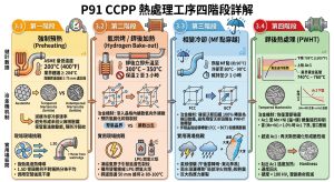
為了修復銲接熱循環造成的微觀組織破壞,並將硬度與潛變強度拉回安全基準線,ASME、AWS D10.10 及 EPRI 共同制定了一套容錯率極低的四階段熱處理程序(包含預熱、氫烘烤、降溫相變、與銲後熱處理)。當這些程序在工廠內執行時,尚能透過自動化爐膛達成;然而,一旦將場景轉換到充滿海風、陣雨及高空管架空間侷限的 CCPP 現場,1.5D 彎頭的每一次銲接熱處理都宛如走鋼索。To repair the microstructural damage caused by the welding thermal cycle and restore hardness and creep strength back to safe baselines, ASME, AWS D10.10, and EPRI collectively established a virtually zero-fault-tolerance four-stage heat treatment procedure (Preheat, Hydrogen Bake-out, Phase Transformation Cooling, and Post-Weld Heat Treatment). While these procedures can be seamlessly executed via automated furnaces in a shop environment, transferring them to a CCPP field setting—plagued by sea breezes, sudden showers, and confined high-altitude pipe racks—turns every heat treatment of a 1.5D elbow into a tightrope walk.
3.1 第一階段:強制預熱與熱傳導控制 (Preheating) / 3.1 Stage 1: Mandatory Preheating and Heat Conduction Control
規範要求與冶金機制 (Code Requirements and Metallurgical Mechanisms):
ASME B31.1 規定,P91 鋼的銲接預熱溫度絕對底線為 200°C (400°F),且業界強烈建議設定在 204°C 以上。預熱的物理目的在於減緩熔池冷卻速率,避免沃斯田鐵急凍成極度脆硬的「未回火麻田散鐵(Untempered Martensite)」,同時為擴散氫保留逸散的熱力學動能。即便是極微小的橋接假銲(Tack welding),若未達預熱溫度即引弧,其周遭產生的未回火麻田散鐵將直接成為氫誘發冷裂紋(Cold Cracking)的起點。ASME B31.1 mandates that the absolute minimum preheat temperature for welding P91 steel is 200°C (400°F), with industry best practices strongly recommending at least 204°C. The physical purpose of preheating is to retard the weld pool cooling rate, preventing the rapid quenching of austenite into extremely brittle “Untempered Martensite,” while preserving thermodynamic kinetic energy for diffusible hydrogen to escape. Even for minuscule tack welds, striking an arc without reaching the preheat temperature will instantly create untempered martensite, serving directly as the initiation point for hydrogen-induced Cold Cracking.
現場實務挑戰 (Field Practical Challenges):
在 CCPP 高達數十公尺的管架上,強勁的自然風速會以極快的對流熱傳導方式剝奪金屬表面的熱能。1.5D 彎頭因具備內弧(Intrados)與外弧(Extrados)的幾何不對稱性,熱量在彎頭本體上的分佈極端不均勻。規範要求必須在距離銲道邊緣至少 75 mm 處,使用校正過的接觸式高溫計逐層(Interpass)記錄溫度。在現場侷限空間與強風干擾下,要確保 1.5D 彎頭 360 度圓周皆穩定維持在 204°C 以上,技術難度與防護成本極高。On CCPP pipe racks soaring tens of meters high, strong natural winds rapidly strip thermal energy from metal surfaces via convective heat transfer. Because 1.5D elbows possess geometric asymmetry between their intrados and extrados, heat distribution across the elbow body is extremely uneven. Codes require that temperatures be monitored interpass using calibrated contact pyrometers at least 75 mm from the weld edge. Under the constraints of confined field spaces and strong wind interference, ensuring the entire 360-degree circumference of a 1.5D elbow remains stably above 204°C involves immense technical difficulty and high weatherproofing costs.
3.2 第二階段:氫烘烤 / 銲後加熱 (Hydrogen Bake-out) 與氫脆化防範 / 3.2 Stage 2: Hydrogen Bake-out / Post-Heating and Hydrogen Embrittlement Prevention
規範要求與冶金機制 (Code Requirements and Metallurgical Mechanisms): 銲接一旦完成,嚴禁使接頭冷卻至環境溫度;必須立即無縫接軌將溫度提升至 300°C – 350°C,並嚴格保溫 2 至 3 小時。此階段的冶金目的是利用足夠的熱能,使滲入晶格內的擴散氫(Diffusible Hydrogen)向管外擴散。若氫氣未能逸散,氫原子將聚集於晶界與微小孔隙中,透過吸附誘發差排發射機制(AIDE),大幅降低表面能並促成微裂紋萌生,嚴重劣化 P91 的機械強度4。 Once welding is complete, allowing the joint to cool to ambient temperature is strictly prohibited; it must seamlessly and immediately be raised to 300°C – 350°C and strictly maintained for 2 to 3 hours. The metallurgical objective of this stage is to leverage sufficient thermal energy to drive Diffusible Hydrogen trapped within the lattice out of the pipe. If hydrogen fails to escape, hydrogen atoms will cluster at grain boundaries and micro-pores, significantly lowering surface energy via the Adsorption-Induced Dislocation Emission (AIDE) mechanism, prompting micro-crack initiation and severely degrading P91’s mechanical strength4.
現場實務挑戰 (Field Practical Challenges): 氫烘烤階段是現場最畏懼「突發斷電」的時刻。若發電機跳脫導致溫度驟降,氫原子會瞬間被凍結在脆性的缺陷中,引發延遲性裂紋。規範嚴格要求,若發生斷電,必須立即啟動備用發電機或使用 LPG 燃氣火炬,將銲道周邊 50 mm 範圍維持在 80-100°C 以上2。在 1.5D 彎頭狹窄的鷹架上,作業人員要在第一時間架設火炬並維持均勻加熱,幾乎是一項不可能的任務。 The hydrogen bake-out stage is the most feared moment for “sudden power outages” in the field. If generator failure causes a sudden temperature drop, hydrogen atoms are instantly frozen within brittle defects, inducing delayed cracking. Codes strictly mandate that in the event of a power failure, backup generators or LPG torches must be immediately deployed to keep a 50 mm zone around the weld above 80-100°C2. On the narrow scaffolding surrounding a 1.5D elbow, expecting operators to instantaneously set up torches and maintain uniform heating is an almost impossible task.
3.3 第三階段:相變冷卻 (Mf 點穿越) 之物理與環境風險 / 3.3 Stage 3: Phase Transformation Cooling (Crossing the Mf Point) and Environmental Risks
規範要求與冶金機制 (Code Requirements and Metallurgical Mechanisms): 完成氫烘烤後,必須移除保溫,讓銲接接頭自然或控制冷卻,穿越麻田散鐵相變完成溫度(Martensitic Finish Temperature, Mf)。P91 鋼的 Mf 點約落在 96°C,業界常規建議必須冷卻至 80°C – 90°C,並維持至少 1 小時,以確保沃斯田鐵 100% 轉變為麻田散鐵2。若未冷卻至 Mf 點即啟動 PWHT,微觀組織中將存在殘留沃斯田鐵。這批沃斯田鐵在 PWHT 完成後的降溫階段,會再次轉變為極脆的「新鮮未回火麻田散鐵」,導致整個 PWHT 程序徹底失效2。 Following the hydrogen bake-out, insulation must be removed to allow the weld joint to naturally or controllably cool through the Martensitic Finish Temperature (Mf). The Mf point for P91 steel lies at approximately 96°C; industry norms recommend cooling down to 80°C – 90°C and holding for at least 1 hour to ensure 100% of the austenite transforms into martensite2. If PWHT is initiated before cooling to the Mf point, Retained Austenite will remain in the microstructure. During the cooling phase post-PWHT, this batch of austenite will transform into extremely brittle “fresh untempered martensite,” rendering the entire PWHT procedure completely ineffective2.
現場實務挑戰 (Field Practical Challenges): 相變過程伴隨著晶格結構從面心立方(FCC)轉變為體心四方(BCT),這會產生顯著的體積膨脹,並在內部累積龐大的相變應力。在此階段,材料處於極度脆弱的狀態。台灣 CCPP 廠區多位於沿海(如大潭、通霄),施工期間常遭遇午後雷陣雨或東北季風侵襲5。若防護雨棚(Weather Enclosure)搭設不善,冰冷的雨水潑灑在正在冷卻的 P9x 1.5D 彎頭上,將產生致命的「局部淬火效應(Quenching Effect)」與熱震(Thermal Shock),其引發的巨大熱應力能輕易將未經回火的麻田散鐵撕裂。 The phase transformation process is accompanied by a lattice structure shift from Face-Centered Cubic (FCC) to Body-Centered Tetragonal (BCT), generating significant volumetric expansion and accumulating massive internal phase-transformation stresses. At this stage, the material is extremely fragile. Most CCPP plants in Taiwan are located along the coast (e.g., Datan, Tongxiao), frequently facing afternoon thunderstorms or northeast monsoons during construction5. If the weather enclosure is poorly erected, cold rain splashing onto the cooling P9x 1.5D elbow will cause a fatal “Quenching Effect” and Thermal Shock. The immense thermal stress induced can easily tear apart the untempered martensite.
3.4 第四階段:銲後熱處理 (PWHT) 之熱力學邊界與加熱技術爭議 / 3.4 Stage 4: Post-Weld Heat Treatment (PWHT) Thermodynamic Boundaries and Heating Technology Controversies
規範要求與冶金機制 (Code Requirements and Metallurgical Mechanisms):
PWHT 是恢復 P9x 潛變強度的終極手段。ASME 規範了 PWHT 的溫度下限為 705°C(1300°F)。然而,PWHT 的上限是一個極度危險的邊界,稱為下臨界溫度(AC1)。EPRI 與冶金學界指出,AC1 溫度受到銲接耗材中錳(Mn)與鎳(Ni)總量的強烈抑制。當 (Mn+Ni) 超過 1.0% 時, AC1會急遽下墜,壓縮了安全加熱窗口。若加熱溫度超過 AC1,材料會發生再沃斯田鐵化(Re-austenitisation),冷卻後形成脆性相;若長時間貼近 AC1 加熱,則會導致過度回火,硬度暴跌至 180 HV 以下,潛變壽命毀於一旦。因此,業界黃金操作區間被嚴格限縮在 740°C – 760°C 之間。PWHT is the ultimate measure to restore the creep strength of P9x. ASME codes mandate a PWHT lower limit of 705°C (1300°F). However, the upper limit of PWHT is an extremely dangerous boundary known as the lower critical temperature (AC1). EPRI and the metallurgical community point out that the AC1 temperature is strongly suppressed by the total amount of Manganese (Mn) and Nickel (Ni) in the welding consumables. When (Mn+Ni) exceeds 1.0%, AC1 plummets sharply, compressing the safe heating window. If the heating temperature exceeds AC1, the material undergoes Re-austenitisation, forming brittle phases upon cooling; if heated too close to AC1 for an extended duration, over-tempering occurs, causing hardness to plummet below 180 HV and destroying the creep lifespan instantly. Thus, the industry’s golden operational window is strictly confined to 740°C – 760°C.
| ASME 規範 / 參考標準Code / Reference | PWHT 溫度下限Min. PWHT Temp | PWHT 溫度上限 (受 Mn+Ni 牽制)Max. PWHT Temp (Mn+Ni Dependent) | 持溫時間 (Soak Time) 規定Hold Time Requirements |
| ASME Section VIII Div. 1 | 705°C (1300°F) | 780°C – 790°C | 1 hr / 25 mm (最少 1 小時 / min 1 hr) |
| ASME B31.1 & B31.3 | 705°C (1300°F) | 775°C (1425°F) | 1 hr / 25 mm (最少 1 小時 / min 1 hr) |
| 業界最佳實務 (EPRI 建議)/
Industry Best Practice (EPRI) |
740°C | 760°C | 2 – 4 小時 (重型厚壁 / heavy sections) |
加熱帶計算與技術瓶頸 (AWS D10.10) (Heating Band Calculations and Technical Bottlenecks):
依據 AWS D10.10,PWHT 必須精確規劃均溫帶(Soak Band, SB)與加熱帶(Heated Band, HB)。均溫帶寬度必須涵蓋銲道本身,並向兩側延伸至少管壁厚度(T)或 50 mm(取其小者)的距離,以確保熱量能沿著徑向與軸向均勻滲透23。 According to AWS D10.10, PWHT must precisely plan the Soak Band (SB) and Heated Band (HB). The soak band width must encompass the weld itself and extend bilaterally by at least the pipe wall thickness (T) or 50 mm (whichever is less) to ensure uniform radial and axial heat penetration23.
在 CCPP 現場,常使用兩種加熱技術,其物理原理在 1.5D 彎頭上產生了截然不同的結果:
In CCPP fields, two heating technologies are commonly employed, whose physical principles yield drastically different outcomes on 1.5D elbows:
- 電阻加熱 (Resistance PWHT):利用陶瓷加熱片透過物理接觸傳導熱量。但在5D 彎頭不規則的曲面上,陶瓷片極難完美貼合。微小的空氣間隙會阻斷熱傳導,導致熱量無法深入管壁內部。為了讓內部達到 740°C,外部陶瓷片可能過度加熱,導致彎頭表面溫度超越 AC1 臨界點,造成冶金破壞24。 Resistance PWHT: Utilizes ceramic heating pads to conduct heat via physical contact. However, on the irregular curved surface of a 1.5D elbow, it is extremely difficult for ceramic pads to fit perfectly. Microscopic air gaps block heat conduction, preventing heat from penetrating deep into the pipe wall. To force the internal temperature to reach 740°C, the external ceramic pads may be overheated, causing the elbow’s surface temperature to surpass the AC1 critical point, leading to metallurgical destruction24.
- 感應加熱 (Induction PWHT):利用交流電磁場在金屬內部產生渦電流(Eddy currents),透過焦耳效應使金屬由內而外自發性升溫。熱轉換效率高達 90%,且升溫極速。然而,感應加熱的磁場分佈與線圈幾何息息相關。在5D 彎頭外弧與內弧的質量與距離差異下,若無高階的磁場解耦演算法(Decoupling strategies)進行分區功率控制,極易產生局部過熱25。且水冷感應線圈與變頻設備極度笨重,在管架上施作難度極高24。 Induction PWHT: Employs an alternating electromagnetic field to generate eddy currents inside the metal, causing spontaneous heating from the inside out via the Joule effect. Heat conversion efficiency reaches up to 90%, and heating is extremely fast. However, the magnetic field distribution of induction heating is highly dependent on coil geometry. Given the mass and distance discrepancies between the extrados and intrados of a 1.5D elbow, without high-level magnetic field decoupling strategies for zoned power control, localized overheating easily occurs25. Furthermore, water-cooled induction coils and inverter equipment are incredibly bulky, making application on pipe racks phenomenally difficult24.
四、 非破壞檢測 (NDE) 與微觀硬度驗證之現場技術瓶頸 / 4. Field Technical Bottlenecks of Non-Destructive Examination (NDE) and Micro-Hardness Verification
完成四階段熱處理後,必須透過科學數據證明 P9x 接頭的可靠度。然而,傳統 1.5D 彎頭的幾何複雜性,為現代檢測技術帶來巨大的測量誤差。After completing the four-stage heat treatment, the reliability of the P9x joint must be proven via scientific data. However, the geometric complexity of traditional 1.5D elbows introduces massive measurement errors for modern NDE technologies.
4.1 微觀硬度量測:UCI 與 Leeb 技術之物理差異 / 4.1 Micro-Hardness Measurement: Physical Differences Between UCI and Leeb Technologies
PWHT 後的硬度檢測是驗證回火效果的唯一防線。P91 的安全靶區極度狹窄:180 – 265 HV10(維氏硬度)。大於 265 HV 代表回火不足,存在延遲裂紋風險;低於 180 HV 代表過度回火或跨越 AC1,潛變強度已嚴重折損。Hardness testing post-PWHT is the sole line of defense to verify tempering effectiveness. P91’s safe target zone is extremely narrow: 180 – 265 HV10 (Vickers hardness). Values above 265 HV indicate insufficient tempering, harboring delayed cracking risks; values below 180 HV signify over-tempering or surpassing AC1, meaning creep strength has been severely compromised.
現場常使用的 Leeb(里氏)硬度計採用動態反彈原理。其撞擊體質量大,產生的壓痕寬達 3-5 mm,這遠大於 P91 銲道關鍵的 HAZ 寬度,導致讀數混雜了母材與銲縫的平均值,無法精確捕捉 HAZ 的硬度峰值。此外,Leeb 硬度計在厚度不足的管壁上會產生「鼓膜效應」,使彈性能量耗散,導致讀數嚴重失真26。 The commonly used Leeb hardness tester in the field operates on the dynamic rebound principle. Its large impact body creates an indentation 3-5 mm wide, far exceeding the critical HAZ width of P91 welds. This mixes the readings of the parent metal and the weld seam, failing to precisely capture the peak hardness in the HAZ. Moreover, Leeb testers produce a “drumhead effect” on thin walls, dissipating elastic energy and causing severely distorted readings26.
現代規範強烈要求使用超音波接觸阻抗(Ultrasonic Contact Impedance, UCI)硬度計。UCI 探頭前端配備維氏鑽石壓頭,壓入金屬的深度僅 50-200 µm,小到足以在不混入母材讀數的情況下專注檢測狹窄的 HAZ 區域26。其運作物理原理是利用壓頭與金屬接觸面積改變時,探頭內部壓電晶體的共振頻率(Frequency shift)變化,並結合材料的楊氏模數(Young’s Modulus)精確換算出維氏硬度26。然而,UCI 檢測需要施加精確的靜態負載(通常為 10N 至 98N 不等),且探頭必須與檢測表面保持絕對垂直27。在 1.5D 彎頭複雜的 3D 曲面與高空鷹架搖晃的環境下,檢測人員幾乎無法確保手持 UCI 探頭的垂直度與穩定施力,大幅增加了測量數值的離散度與誤判率。 Modern codes strongly advocate for Ultrasonic Contact Impedance (UCI) hardness testers. The UCI probe tip features a Vickers diamond indenter penetrating only 50-200 µm into the metal—small enough to exclusively measure the narrow HAZ without bleeding into parent metal readings26. Its operating physical principle utilizes the frequency shift of the internal piezoelectric crystal as the contact area changes, precisely calculating Vickers hardness in conjunction with the material’s Young’s Modulus26. However, UCI requires precise static loading (typically 10N to 98N) and the probe must remain perfectly perpendicular to the tested surface27. In the shaky environment of high-altitude scaffolding and the complex 3D curves of a 1.5D elbow, inspectors can barely guarantee perpendicularity and stable pressure with a handheld UCI probe, drastically increasing measurement scatter and misjudgment rates.
4.2 體積性檢測:PAUT 與 RT 之可靠度分析 / 4.2 Volumetric Examination: Reliability Analysis of PAUT and RT
P9x 材料的微觀損傷往往以晶界微裂紋或層間未熔合(Lack of fusion)等「平面型缺陷(Planar flaws)」形式存在。傳統的射線檢測(RT)依賴射線的體積衰減,對這類垂直於底片的平面缺陷極度不敏感,漏判率極高30。 Micro-damage in P9x materials frequently manifests as “Planar Flaws” such as grain boundary micro-cracks or lack of inter-run fusion. Traditional Radiographic Testing (RT) relies on volumetric attenuation of rays, making it highly insensitive to such planar defects perpendicular to the film, resulting in exceptionally high miss rates30.
為彌補此缺陷,ASME 規範許可採用相控陣列超音波檢測(Phased Array Ultrasonic Testing, PAUT)取代 RT15。PAUT 探頭內部陣列了 16 至 128 顆獨立的壓電晶片,透過精密計算的「聚焦法則(Focal laws)」控制各晶片的發射延遲時間,實現超音波束的電子偏轉(Beam steering)與多角度扇形掃描(S-Scan)32。配合 CIVA 等軟體進行聲學模擬,PAUT 能精準描繪出銲道內部的立體缺陷圖像31。可靠度模型(POD, Probability of Detection)分析顯示,PAUT 對於平面缺陷的偵測機率遵循邏輯迴歸模型: To compensate for this flaw, ASME codes permit the substitution of RT with Phased Array Ultrasonic Testing (PAUT) 15. A PAUT probe contains an array of 16 to 128 independent piezoelectric crystals. By employing meticulously calculated “Focal Laws” to control the emission delay of each crystal, it achieves electronic beam steering and multi-angle sectorial scanning (S-Scans) 32. Coupled with acoustic simulation software like CIVA, PAUT can precisely delineate 3D defect images inside the weld31. Probability of Detection (POD) modeling analysis shows that PAUT’s detection probability for planar flaws follows a logistic regression model:
POD(a)=exp(α+βlna)/[1+exp(α+βlna)]
其對微小裂紋的檢出率以數量級之差碾壓 RT30。 Its detection rate for micro-cracks completely overwhelms RT by orders of magnitude30.
然而,PAUT 的精準度極度依賴超音波的幾何耦合。檢測時,探頭必須裝載於與管壁曲率完全吻合的聲學楔塊(Wedge)上,並透過編碼器(Encoder)進行掃描。在 1.5D 彎頭的漸變曲面上,尤其是內弧與外弧過渡區,標準楔塊無法緊密貼合,導致嚴重的聲束發散與訊號盲區。若強行掃描,產生的幾何假訊號會干擾判讀,這使得 1.5D 彎頭的 NDE 成為 CCPP 現場品保的最薄弱環節。However, the precision of PAUT relies heavily on ultrasonic geometric coupling. During inspection, the probe must be mounted on an acoustic wedge perfectly matched to the pipe’s curvature and scanned using an encoder. On the graduating curves of a 1.5D elbow, especially the transition zones between the intrados and extrados, standard wedges cannot fit tightly, leading to severe beam divergence and signal blind spots. If forcibly scanned, the resulting geometric false signals interfere with interpretation, making the NDE of 1.5D elbows the weakest link in CCPP field quality assurance.
五、 ASME B31J 應力解耦與 CCPP 宏觀流固耦合破壞 / 5. ASME B31J Stress Decoupling and Macroscopic Fluid-Solid Coupling Failures in CCPPs
跨越微觀冶金的缺陷,1.5D 彎頭在宏觀力學與流體動力學上的表現同樣堪慮。2026 年即將全面強制實施的 ASME B31J 規範,徹底顛覆了高能管線的應力分析邊界,揭露了傳統 1.5D 彎頭的致命弱點1。 Beyond micro-metallurgical defects, the macroscopic mechanical and fluid dynamic performance of 1.5D elbows is equally concerning. The ASME B31J code, slated for full mandatory enforcement by 2026, completely upends the stress analysis boundaries for high-energy piping, exposing the fatal vulnerabilities of traditional 1.5D elbows1.
5.1 ASME B31J 應力強度因子 (SIF) 之三維解耦 / 5.1 Three-Dimensional Decoupling of Stress Intensification Factors (SIF) in ASME B31J
在過去半個世紀中,管線應力設計高度依賴 ASME B31.1 Appendix D 的經驗公式。該公式過度簡化了幾何不連續處的受力狀態,強行賦予單一的應力強度因子(Stress Intensification Factor, SIF),未能真實反映三維空間中彎矩的差異作用。For the past half-century, piping stress design heavily relied on the empirical formulas of ASME B31.1 Appendix D. These formulas oversimplified the stress states at geometric discontinuities, forcefully assigning a single Stress Intensification Factor (SIF) and failing to truly reflect the differential effects of bending moments in three-dimensional space.
新版 ASME B31J 基於真實尺寸的幾何疲勞測試與高階有限元素分析(FEA),定義了嚴密的「柔性特徵模型(Flexibility Characteristic, h)」:The new ASME B31J, based on real-size geometric fatigue testing and advanced Finite Element Analysis (FEA), defined a rigorous “Flexibility Characteristic model (h)”:
h=T⋅R1/r22
其中,T 為管線公稱壁厚,R1 為彎曲半徑,r2 為管線平均半徑34。《h》值越小,代表彎管在受彎矩作用時,截面越容易發生劇烈的橢圓化畸變。 Where T is the nominal pipe wall thickness, R1 is the bend radius, and r2 is the mean pipe radius34. A smaller h value indicates that the bend’s cross-section is more prone to severe ovalization distortion when subjected to bending moments.
基於此數學模型,B31J 將 SIF 進行了精確的三維解耦:Based on this mathematical model, B31J precisely decoupled the SIF in three dimensions:
- 面內應力強化係數 (ii) / In-Plane SIF (ii):當彎矩作用於彎管平面內,迫使彎管發生「張開」或「閉合」時所套用的係數1。Applied when the bending moment acts within the bend plane, forcing the bend to “open” or “close”1.
- 面外應力強化係數 (io) / Out-of-Plane SIF (io):當彎矩迫使彎管發生橫向「扭曲」時所套用的係數。Applied when the bending moment forces the bend into lateral “twisting.”
- 扭轉應力強化係數 (it) / Torsional SIF (it):B31J 首次強制將扭轉力矩納入疲勞計算,終結了過去 it預設為0 的誤差年代。B31J mandates the inclusion of torsional moments in fatigue calculations for the first time, ending the erroneous era of defaulting it to 1.0.
| 管件幾何種類Fitting Geometry Type | 彎曲半徑 (R1)Bend Radius | 柔性特徵值 (h)Flexibility Char. | B31J 計算下之 SIF 極值分佈SIF Extremes under B31J | 系統設計之工程代價Engineering Toll on System Design |
| 傳統 1.5D 銲接彎頭/Trad. 1.5D Welded Elbow | 極小/Very Small | 偏低 (抗橢圓化剛度弱)/Low (Weak ovalization resistance) | 3.0 ~ 5.0 的極高集中值5/Extremely high conc. (3.0~5.0) 5 | 熱膨脹產生的交變應力被不合理放大數倍。必須配置大量昂貴的恆力彈簧吊架或膨脹環以吸收應力。/Alternating stresses from thermal expansion are unreasonably multiplied. Requires massive expensive constant-effort hangers or expansion loops to absorb stress. |
| 3D / 5D 冷作彎管/3D / 5D Cold Bend | 大 (3D ~ 5D)/Large | 顯著提升 (截面剛度強大)/Significantly higher (Strong section stiffness) | 趨近於 1.0 極限值35/Approaching the ideal 1.0 limit35 | 完美實現系統應力的平滑轉移,徹底卸除低週疲勞的幾何放大因子,精簡管架設計。/Perfectly realizes smooth stress transfer, thoroughly offloading geometric magnification factors for low-cycle fatigue, streamlining pipe rack design. |
當 1.5D 彎頭高達 3.0-5.0 的應力放大效應,精準疊加在 P9x 銲道脆弱的 ICHAZ 上時,在 CCPP 頻繁起停的熱膨脹位移交變下,宏觀應力將毫不留情地撕裂微觀的潛變空洞,引發災難性的破裂。When the massive 3.0-5.0 stress amplification effect of a 1.5D elbow precisely overlaps the fragile ICHAZ of a P9x weld, under the alternating thermal expansion displacements caused by frequent CCPP start-stops, macroscopic stresses will mercilessly tear apart the microscopic creep voids, sparking catastrophic ruptures.
5.2 流體動力學、狄恩渦流與流體加速腐蝕 (FAC) / 5.2 Fluid Dynamics, Dean Vortices, and Flow-Accelerated Corrosion (FAC)
除了固體力學的缺陷,高能蒸汽流經 1.5D 極短曲率的彎頭時,流體力學行為也會發生劇變。流體受到強大離心力擠壓,會產生二次渦流,其強度由「狄恩數(Dean Number, De)」量化:Beyond solid mechanics defects, when high-energy steam flows through the extremely short curvature of a 1.5D elbow, fluid dynamic behaviors also undergo drastic changes. The fluid, squeezed by powerful centrifugal forces, generates secondary vortices whose intensity is quantified by the “Dean Number (De)”:
De=Re√D/2Rc
(Re 為雷諾數,Rc 為曲率半徑,D 為管徑)。(Where Re is the Reynolds number, Rc is the radius of curvature, and D is the pipe diameter).
當曲率半徑極小時,狄恩數呈指數級飆升,引發嚴重的邊界層流體分離(Flow separation)。這股高強度的亂流會猶如砂紙般,強烈剝離 P9x 管壁內側自然生成的緻密磁鐵礦(Fe3O4)保護層。一旦保護層被剝離,暴露出的裸金屬將迅速被高溫蒸汽氧化,隨後再次被沖刷,形成惡性循環的「流體加速腐蝕(Flow-Accelerated Corrosion, FAC)」。When the radius of curvature is extremely small, the Dean Number skyrockets exponentially, triggering severe boundary layer flow separation. This high-intensity turbulence acts like sandpaper, violently stripping away the dense magnetite (Fe3O4) protective layer naturally generated on the inner wall of the P9x pipe. Once the protective layer is stripped, the exposed bare metal is rapidly oxidized by the high-temperature steam, only to be washed away again, forming a vicious cycle of “Flow-Accelerated Corrosion (FAC).”
5.3 聲學共振 (Acoustic Resonance) 與疲勞交變應力 / 5.3 Acoustic Resonance and Fatigue Alternating Stresses
CCPP 機組作為電網調峰主力,常處於快速升降載狀態,管內蒸汽流速變化劇烈。當高速氣流流經 1.5D 彎頭的幾何突變點與內部環向銲縫時,會產生高頻的渦流脫落(Vortex shedding)。渦流脫落頻率可透過斯特勞哈爾數(Strouhal Number, St)進行評估:As the mainstays of grid peak-shaving, CCPP units often operate in states of rapid load ramping, causing violent fluctuations in internal steam velocities. When high-speed airflow passes through the geometric discontinuity and internal circumferential welds of a 1.5D elbow, high-frequency vortex shedding occurs. The vortex shedding frequency can be evaluated via the Strouhal Number (St):
St=(f⋅D)/v
若操作過程中,氣流流速 v 的變化導致渦流脫落頻率 f 剛好與管線內部氣柱的固有聲學頻率重合,系統將觸發「頻率鎖定(Frequency Lock-in)」現象,產生能量極高的聲學共振。這股共振所帶來的高週疲勞(High-Cycle Fatigue)應力,會與熱膨脹產生的低週疲勞(Low-Cycle Fatigue)應力疊加,加速 P9x 銲道的斷裂進程。If changes in the airflow velocity v during operation cause the vortex shedding frequency f to coincide precisely with the inherent acoustic frequency of the internal gas column, the system will trigger a “Frequency Lock-in” phenomenon, generating extremely high-energy acoustic resonance. The High-Cycle Fatigue stresses brought by this resonance superimpose with the Low-Cycle Fatigue stresses caused by thermal expansion, accelerating the fracture progression of P9x welds.
5.4 台灣高鹽害海岸環境之氯離子應力腐蝕開裂 (Cl-SCC) / 5.4 Chloride Stress Corrosion Cracking (Cl-SCC) in Taiwan’s High-Salinity Coastal Environments
更不可忽視的是台灣獨特的地理氣候。多數大型 CCPP 電廠(如大潭、興達、通霄)皆建置於迎風面的高鹽分海岸地區。大氣環境中高濃度的氯離子(Chloride ions)結合海鹽飛沫,極易穿透保溫層,附著於高溫管線表面。Even more unignorable is Taiwan’s unique geographic and climatic environment. The majority of large CCPP power plants (e.g., Datan, Hsinta, Tongxiao) are built in windward, high-salinity coastal areas. High concentrations of chloride ions in the atmosphere, combined with sea salt spray, easily penetrate insulation layers and adhere to the surfaces of high-temperature piping.
在傳統 1.5D 銲接管線中,即便經過嚴格的 PWHT,銲道與 HAZ 仍必然殘留一定比例的拉伸應力。在高溫服役、局部殘餘拉應力與高活性氯離子的三方耦合作用下,金屬表面的鈍化膜會遭到破壞,引發微觀點蝕(Pitting)。這些點蝕坑在銲接熱影響區的高差排密度與晶界處會迅速演化為應力集中源,誘發破壞性的氯離子應力腐蝕開裂(Cl-SCC)。裂紋尖端的微環境酸化(pH 值驟降)會加速金屬陽極溶解,導致裂紋沿著脆弱的晶界(Intergranular)快速擴展,造成突發性管系破裂。In traditional 1.5D welded piping, even after rigorous PWHT, the weld and HAZ inevitably retain a certain proportion of tensile stress. Under the three-way coupling effect of high-temperature service, localized residual tensile stress, and highly active chloride ions, the metal’s surface passivation film is destroyed, triggering micro-pitting. These pitting holes in the high-dislocation-density and grain boundaries of the HAZ rapidly evolve into stress concentration sources, inducing destructive Chloride Stress Corrosion Cracking (Cl-SCC). Micro-environmental acidification (a sudden pH drop) at the crack tip accelerates the metal’s anodic dissolution, causing cracks to rapidly propagate along fragile grain boundaries (intergranular cracking) and resulting in sudden pipe system ruptures.
六、 1.5D 電銲彎頭、5″ 以下冷作彎管與 6″ 以上熱彎管之實務差異與多維度視角分析 / 6. Practical Differences and Multi-Dimensional Perspective Analysis of 1.5D Welded Elbows, Sub-5″ Cold Bends, and Over-6″ Hot Bends
在捨棄高風險的 1.5D 短半徑電銲彎頭,轉而擁抱廠內預製彎管的技術演進中,工程實務依據管徑與壁厚,發展出兩條截然不同的製造路徑:5″ 以下之 3D/5D 大半徑冷作彎管(Cold Bends),以及 6″ 以上之高週波感應熱彎管(Hot Induction Bends)。這三種管件在 CCPP 建廠生態系中,為不同利害關係人帶來了截然不同的決策考量。In the technological evolution of abandoning high-risk 1.5D short-radius welded elbows in favor of shop-prefabricated bends, engineering practices have developed two distinct manufacturing paths based on pipe diameter and wall thickness: Sub-5″ 3D/5D large-radius Cold Bends, and Over-6″ Hot Induction Bends. Within the CCPP construction ecosystem, these three types of fittings present distinctly different decision-making considerations for various stakeholders.
6.1 業主維護管理及營運決策視角 / 6.1 Owner’s Perspective on Maintenance Management and Operational Decision-Making
從電廠業主的角度出發,決策核心在於「全生命週期成本(Lifecycle Cost)」與「長期營運可靠度(Long-term Operational Reliability)」。From the perspective of power plant owners, the core decision-making lies in “Lifecycle Cost” and “Long-term Operational Reliability.”
採用傳統 1.5D 電銲彎頭雖然初期材料採購成本低,但在長達數十年的服役期內,業主必須為高潛在的第四型潛變裂紋承擔極大的無預警破管風險11。每次機組歲修大修(Turnaround)期間,業主需編列龐大預算,針對這些高應力區的現場銲道執行頻繁的 PAUT、金相覆膜(Replica)及 UCI 硬度抽測。 While employing traditional 1.5D welded elbows has low initial material procurement costs, over a service life spanning decades, owners must bear the immense risk of unpreventable pipe bursts caused by high-potential Type IV creep cracks11. During each unit’s turnaround maintenance, owners must allocate vast budgets to execute frequent PAUT, metallographic replicas, and UCI hardness spot checks on these high-stress field welds.
相較之下,改採 5″ 以下冷作彎管(多用於輔助蒸汽、洩水管線)與 6″ 以上熱彎管(主蒸汽、高溫再熱段),可將最脆弱的環向銲道移出幾何轉折與高應力熱點。這種「以彎代銲」策略,大幅削減了法規強制要求的在役檢查(ISI)銲口數量,直接縮短了歲修工期並提升機組的發電可用率(Availability),是防範災難性工安事故、確保電網穩定調度的最佳投資。By contrast, switching to sub-5″ cold bends (mostly used for auxiliary steam and drain lines) and over-6″ hot bends (main steam, hot reheat sections) removes the most vulnerable circumferential welds away from geometric turns and high-stress hotspots. This “bend-instead-of-weld” strategy drastically cuts down the number of welds subject to mandatory In-Service Inspections (ISI), directly shortening turnaround durations and enhancing the unit’s power generation Availability. It is the optimal investment for preventing catastrophic industrial accidents and ensuring stable grid dispatch.
6.2 EPC 承包商與設計單位之空間佈置與應力實務考量 / 6.2 EPC Contractor and Engineering Unit’s Practical Considerations on Spatial Layout and Stress
對於 EPC 統包商及管線應力工程師而言,挑戰在於如何在有限的管架空間內滿足 ASME B31J 規範的嚴格要求。For EPC contractors and piping stress engineers, the challenge lies in fulfilling the stringent requirements of the ASME B31J code within limited pipe rack spaces.
1.5D 彎頭體積緊湊,確實能節省廠區的實體空間。然而,在 B31J 規範強制實施後,1.5D 彎頭面內外極高的應力強度因子(SIF = 3.0 ~ 5.0),使得設計工程師必須在管線佈局中加入極度佔據空間的膨脹環(Expansion Loops),或是大量採用造價昂貴、需定期維護的恆力彈簧吊架與液壓防震器(Snubbers)來吸收膨脹位移5。 1.5D elbows are highly compact and genuinely save physical space within the plant. However, following the mandatory enforcement of the B31J code, the extremely high in-plane and out-of-plane SIFs (3.0 ~ 5.0) of 1.5D elbows compel design engineers to incorporate massively space-consuming Expansion Loops into the piping layout, or broadly employ expensive, maintenance-heavy constant-effort spring hangers and hydraulic snubbers to absorb expansion displacements5.
導入 3D/5D 彎管後,儘管單一管件的幾何佔地變大,但其 SIF 趨近於 1.0 的絕對優勢,使得整條管線的應力分布變得極度平滑:After introducing 3D/5D bends, despite the geometric footprint of the single fitting increasing, its absolute advantage of having an SIF approaching 1.0 renders the stress distribution of the entire pipeline incredibly smooth:
- 5″ 以下冷作彎管 (Sub-5″ Cold Bends): 管徑較小,可以直接使用數控(CNC)冷彎機成型,成本效益極高,設計上能靈活閃避管架干涉物。With smaller pipe diameters, they can be directly formed using CNC cold bending machines, yielding high cost-effectiveness and allowing flexible design maneuvering around pipe rack obstructions.
- 6″ 以上熱彎管 (Over-6″ Hot Bends): 主蒸汽管線管徑粗、壁厚大,早已超越冷彎機的極限,必須仰賴高週波感應加熱彎管。由於熱彎管的曲率穩定,設計工程師能藉此大幅精簡管架設計,降低整體鋼結構的噸數與建造成本。Main steam pipes with large diameters and thick walls far exceed the limits of cold bending machines and must rely on hot induction bending. Because the curvature of hot bends is stable, design engineers can drastically streamline pipe rack designs, lowering the overall steel structure tonnage and construction costs.
6.3 廠務管理者對高能管線營運可靠度之要求 / 6.3 Plant Manager’s Requirements for the Operational Reliability of High-Energy Piping
廠務管理者直接面臨機組的熱效率與日常維運壓力。使用 1.5D 電銲彎頭時,其極短的轉彎半徑在內部產生劇烈的狄恩渦流與嚴重的流體邊界層分離。這不僅增加了系統的壓力降(Pressure Drop)、吞噬了蒸汽輪機的發電效率,更會引發高頻的聲學共振與流體加速腐蝕(FAC)。
Plant managers directly face the pressures of unit thermal efficiency and daily maintenance operations. When using 1.5D welded elbows, the extremely short turning radius produces violent Dean vortices and severe fluid boundary layer separation internally. This not only increases system Pressure Drop—cannibalizing the steam turbine’s power generation efficiency—but also triggers high-frequency acoustic resonance and Flow-Accelerated Corrosion (FAC).
改用 5″ 以下冷作彎管與 6″ 以上熱彎管後,流體動力學獲得顯著改善。流線能平滑順著大曲率半徑流動,壓降可減少 20% 至 30%。此外,管內壁的磁鐵礦保護膜不再受到劇烈亂流剝離,徹底排除了 FAC 的根源。這使得廠務管理者不需頻繁面臨管線沖蝕減薄的測厚警報,大幅降低了日常維運的精神負擔。After switching to sub-5″ cold bends and over-6″ hot bends, fluid dynamics are significantly improved. Flow lines can glide smoothly along the large curvature radius, cutting pressure drops by 20% to 30%. Moreover, the magnetite protective film on the inner pipe wall is no longer subjected to violent turbulent stripping, thoroughly eliminating the root cause of FAC. This spares plant managers from frequently facing thickness-measurement alarms regarding piping erosion thinning, greatly alleviating the mental burden of daily operations.
6.4 彎管施作協力廠商之技術極限與因應策略 / 6.4 Bending Subcontractors’ Technical Limits and Mitigation Strategies
將加工從現場轉移至工廠,冷、熱彎管協力廠商面臨著截然不同的冶金挑戰:By shifting fabrication from the field to the shop, cold and hot bending subcontractors face distinctly different metallurgical challenges:
- 5″ 以下 3D/5D 冷作彎管 (Sub-5″ 3D/5D Cold Bends): 工法的核心在於對抗材料的回彈效應(Spring-back)與幾何畸變。依據 ASME B31.1,管件在冷作過程中的外側壁厚減薄率與截面橢圓化必須嚴格控制。當冷應變量超過法規界線(例如 20%-25%)時,P91 材料的晶格會發生嚴重變形,引發應變老化(Strain Aging),導致衝擊韌性暴跌。協力廠商必須精確執行次臨界彎後熱處理(Subcritical PBHT),在 705°C – 760°C 區間釋放殘餘應力,且絕不能破壞原有的微觀析出相。The core of the methodology is battling material Spring-back and geometric distortion. Per ASME B31.1, extrados wall thinning and cross-sectional ovalization during cold bending must be strictly controlled. When cold strain exceeds code boundaries (e.g., 20%-25%), the P91 material lattice undergoes severe deformation, triggering Strain Aging and causing impact toughness to plummet. Subcontractors must precisely execute a Subcritical Post-Bend Heat Treatment (PBHT) in the 705°C – 760°C range to release residual stresses without destroying the original micro-precipitates.
- 6″ 以上高週波感應熱彎管 (Over-6″ Hot Induction Bends): 此工法利用強大的環形感應線圈,將 P91 管件局部加熱至 AC3(約 1000°C – 1050°C)以上的沃斯田鐵化溫度,隨後一邊推進一邊彎曲,再輔以水或空氣急冷。這等於將 P91 重新煉製了一次。施作協力廠商的最高技術門檻在於,熱彎完成後,管件微觀組織已完全走樣,極易析出危害性的 Laves 相4。因此,協力廠商必須具備大型、高溫均勻度極佳的自動化熱處理爐,強制對整支熱彎管執行一次完整的「正常化 + 回火(Normalizing & Tempering)」熱處理,以重新塑造 M23C6 與 MX 奈米析出相,否則管件的潛變強度將直接歸零13。This method uses a powerful ring-shaped induction coil to locally heat the P91 pipe above its austenitization temperature AC3 (approx. 1000°C – 1050°C), simultaneously pushing and bending, followed by rapid water or air quenching. This essentially re-forges the P91 steel. The highest technical hurdle for subcontractors is that, post-bending, the microstructure is completely distorted and highly prone to precipitating detrimental Laves phases. Therefore, the subcontractor must possess large automated heat-treatment furnaces with excellent high-temp uniformity to forcefully subject the entire hot bend to a complete “Normalizing & Tempering” heat treatment. This re-forges the M23C6 and MX nano-precipitates; otherwise, the pipe’s creep strength directly drops to zero13.
6.5 潁璋工程「能彎不銲」三合一工法之導入與 P9x 高能管線合規性深度分析 / 6.5 Introduction of Ying-Zhang Engineering’s “Bend-Instead-of-Weld” 3-in-1 Method and In-Depth Compliance Analysis for P9x High-Energy Piping
在 CCPP 頻繁起停的嚴苛熱力學循環下,傳統管線銲道極易因疲勞與潛變耦合機制而提早損壞。為徹底解決此痛點,國內業界引進了「潁璋工程」所提倡之「能彎不銲(Bend-instead-of-Weld)」核心理念,並透過其獨創的「三合一工法」——即結合 CNC 精密冷作彎管設計、中頻感應彎後熱處理(IH-PBHT)與供應鏈整合管理——將 P9x 高能管線的製造風險降至最低36。 Under the harsh thermodynamic cycles of frequent CCPP start-stops, traditional pipe welds are highly prone to premature failure due to coupled fatigue and creep mechanisms. To thoroughly resolve this pain point, the domestic industry introduced the core philosophy of “Bend-instead-of-Weld” championed by Ying-Zhang Engineering. Through its unique “3-in-1 Method”—integrating precision CNC cold bend design, Intermediate-Frequency Induction Heating PBHT (IH-PBHT), and supply chain integration management—the manufacturing risks of P9x high-energy piping are minimized36.
- CCPP 頻繁起停物理瞬態下之應變率與 IH-PBHT 放寬適用性分析 (Analysis of Strain Rate and IH-PBHT Applicability Relaxation under Physical Transients of CCPP Frequent Start-Stops)
CCPP 燃氣機組肩負電網調峰任務,每日面臨劇烈的熱瞬態與壓力交變。當採用 3D 或 5D 大半徑冷作彎管取代 1.5D 彎頭時,雖然大幅降低了宏觀應力強度因子(SIF),但冷作變形本身會對管材微觀晶格造成扭曲。依據純幾何關係推算,5D 彎管的理論最大拉伸應變率約為 10.0%,而 3D 緊密彎管的冷應變率則可飆升至 16.7%。CCPP gas units shoulder grid peak-shaving tasks, facing severe thermal transients and pressure alternations daily. When using 3D or 5D large-radius cold bends to replace 1.5D elbows, despite drastically lowering the macroscopic SIF, cold deformation itself distorts the pipe’s micro-lattice. Calculated via pure geometric relationships, the theoretical maximum tensile strain rate of a 5D bend is approx. 10.0%, while the cold strain rate of a tight 3D bend can soar to 16.7%.
這類介於 5% 至 20% 之間的高應變率,若未經妥善處理,將引發嚴重的應變時效,導致 P91 材料的衝擊韌性暴跌。針對此區間的冷應變,ASME B31.1 第 3 節(Table 129.3.1-1)明確規範了應變極限與熱處理要求。潁璋工程的技術突破在於,針對 5%~20% 應變率的 3D/5D P91 冷作厚壁管,無需進行破壞原有微觀組織、風險極高的全面正常化與回火(N&T),而是精準採用「次臨界感應加熱彎後熱處理(Subcritical IH-PBHT)」。High strain rates falling between 5% and 20%, if left improperly treated, will trigger severe strain aging, causing P91’s impact toughness to plummet. For cold strains in this range, ASME B31.1 Section 3 (Table 129.3.1-1) clearly defines strain limits and heat treatment requirements. Ying-Zhang Engineering’s technological breakthrough lies in targeting 3D/5D P91 cold-formed thick-walled pipes with 5%~20% strain rates: bypassing the highly risky full Normalizing & Tempering (N&T) which destroys the original microstructure, they precisely employ “Subcritical Induction Heating Post-Bend Heat Treatment (Subcritical IH-PBHT).”
- 潁璋工程冷作彎管三合一工法對於 P9x 規範之合規性與冶金優勢 (Compliance and Metallurgical Advantages of Ying-Zhang Engineering’s Cold Bending 3-in-1 Method under P9x Codes)
潁璋工程所執行的次臨界 IH-PBHT,將加熱溫度嚴格且精準地控制在 705°C 至 760°C 的狹窄安全區間內(嚴格低於 P91 的 AC1 下臨界溫度)。從法規與合規性角度檢視,此三合一工法完美契合 ASME B31.1 與 B31.3 的嚴苛要求:The Subcritical IH-PBHT executed by Ying-Zhang Engineering strictly and precisely controls heating temperatures within the narrow safe zone of 705°C to 760°C (strictly below P91’s AC1 lower critical temp). Evaluated from a code and compliance perspective, this 3-in-1 method perfectly aligns with the stringent requirements of ASME B31.1 and B31.3:
- 微觀組織保護 (Microstructural Protection): 由於加熱溫度未跨越 AC1 線,材料不會發生沃斯田鐵相變。這意味著 P91 原本出廠時精心調控的回火麻田散鐵基體,以及晶界上扮演潛變強度關鍵支撐的 M23C6 與 MX 奈米碳氮化物析出相,皆能被完整保留而不受破壞。Because the heating temp does not cross the AC1 line, the material does not undergo austenitic phase transformation. This means P91’s meticulously tuned tempered martensite matrix from the mill, along with the M23C6 and MX nano-carbonitride precipitates on grain boundaries acting as crucial creep strength pillars, are completely preserved and undamaged.
- 殘餘應力與加工硬化消除 (Elimination of Residual Stress and Work Hardening): 精密的恆溫控制促使冷彎過程中糾結的高密度差排發生重排與回復,徹底釋放了足以誘發氯離子應力腐蝕開裂(Cl-SCC)的成型殘餘應力,並恢復了材料的延展性與長期潛變韌性。Precise constant temperature control encourages the entangled high-density dislocations from the cold bending process to rearrange and recover. This thoroughly releases forming residual stresses capable of inducing Cl-SCC and restores the material’s ductility and long-term creep toughness.
- 品保與管理優化 (QA and Management Optimization): 透過供應鏈管理的整合(三合一工法),從源頭的 CNC 冷彎設計、無縫銜接的 IH-PBHT,到最終的非破壞檢測驗證,形成嚴密的閉環。這不僅在設計端落實了「能彎不銲」減少高危險銲口的理念,更在製造端確保了每一個冷作彎管的幾何尺寸與冶金性質皆具備高度的一致性與可追溯性。Through supply chain management integration (the 3-in-1 method), a rigorous closed-loop is formed: from upstream CNC cold bend design, to seamlessly linked IH-PBHT, down to final NDE verification. This not only actualizes the “Bend-instead-of-Weld” philosophy at the design end to reduce high-risk welds, but also ensures a high degree of consistency and traceability in the geometric dimensions and metallurgical properties of every cold bend at the manufacturing end.
七、 結論與技術決策演進 / 7. Conclusion and Evolution of Technical Decision-Making
綜上深度剖析,對於 P91/P92 等對熱循環極度敏感的高能 CSEF 管線而言,在 CCPP 建廠現場的高空、惡劣氣候環境中,採用傳統 1.5D 銲接彎頭進行管網轉向,是一項同時牴觸「物理冶金學、熱力學、固體應力分析與流體動力學」四大領域工程極限的高風險決策。In summary of this in-depth analysis, for high-energy CSEF piping like P91/P92 that is extremely sensitive to thermal cycles, employing traditional 1.5D welded elbows for pipeline turning in the high-altitude, harsh-climate field environments of CCPP construction is a high-risk decision that simultaneously violates engineering limits across four major domains: Physical Metallurgy, Thermodynamics, Solid Stress Analysis, and Fluid Dynamics.
- 微觀冶金與熱處理的不確定性 (Uncertainty in Micro-Metallurgy and Heat Treatment): 在現場侷限環境中,極難完美控制 204°C 的強制預熱、無縫接軌的氫烘烤、防範熱震的 Mf 點降溫相變,以及避開 AC1 陷阱的精確 740-760°C PWHT。任何單一環節的失誤,都會在 ICHAZ 中埋下第四型潛變裂紋的定時炸彈。In confined field environments, perfectly controlling the 204°C mandatory preheat, seamless hydrogen bake-out, thermal-shock-proof cooling past the Mf point, and precisely executed 740-760°C PWHT while dodging the AC1 trap is exceedingly difficult. A lapse in any single step plants a ticking time bomb for Type IV creep cracking in the ICHAZ.
- 力學與檢測的幾何侷限 (Geometric Limitations in Mechanics and NDE):5D 彎頭在 ASME B31J 規範下呈現出高達 3.0-5.0 的應力放大效應。同時,其不規則的 3D 曲率阻礙了 UCI 硬度檢測的垂直施力與 PAUT 楔塊的超音波耦合,使得重大微觀缺陷極易在 NDE 階段被漏判。Under ASME B31J, 1.5D elbows exhibit massive stress amplification effects of 3.0-5.0. Simultaneously, their irregular 3D curvatures hinder the perpendicular pressure required for UCI hardness testing and the ultrasonic coupling of PAUT wedges, making it highly probable for major micro-defects to be missed during the NDE phase.
- 流固耦合與環境腐蝕的疊加威脅 (Superimposed Threats of Fluid-Solid Coupling and Environmental Corrosion): 極小的曲率半徑引發了高強度的狄恩渦流與聲學共振,加速內部 FAC 腐蝕;而銲道殘餘拉應力則成為外部海岸氯離子應力腐蝕開裂 (Cl-SCC) 的完美溫床。The extremely tight radius of curvature triggers intense Dean vortices and acoustic resonance, accelerating internal FAC corrosion; meanwhile, residual tensile stresses in the weld provide a perfect breeding ground for external coastal Chloride Stress Corrosion Cracking (Cl-SCC).
最佳化工程解決方案 (Optimized Engineering Solution): 為了徹底根絕上述隱患,工程界與決策者應順應 ASME B31J 規範演進與國際高能管線技術趨勢(如潁璋工程所提倡之三合一工法理念),全面採用工廠預製的 3D/5D 大半徑冷作彎管(Cold Bending)或高週波感應彎管(Hot Induction Bend) 取代傳統的現場 1.5D 銲接彎頭5。 To thoroughly eradicate these hidden dangers, the engineering sector and decision-makers should conform to the ASME B31J code evolution and international high-energy piping tech trends (e.g., the 3-in-1 method philosophy advocated by Ying-Zhang Engineering), comprehensively replacing traditional field 1.5D welded elbows with shop-prefabricated 3D/5D large-radius Cold Bends or Hot Induction Bends5.
透過「以彎代銲(Bend rather than weld)」的顛覆性技術,在幾何上將致命的環向銲道推移至系統應力與流體流場最平緩的直管過渡區。此舉不僅將 SIF 大幅降至趨近於 1.0 的安全極限值,徹底消除了 FAC 與頻率鎖定聲學共振的生成要件;更透過在室內受控工廠環境中執行精密計算的次臨界彎後熱處理(Subcritical PBHT, 705°C – 760°C)或整支熱彎管的完全正常化與回火,在不破壞 P9x 鋼原有 M23C6 與 MX 奈米強化析出相的前提下,完美促使差排重排,徹底釋放成型殘餘應力1。這種從根本上拔除銲接微觀缺陷與幾何應力放大的策略,將為台灣 CCPP 燃氣發電廠在未來數十年的極端調峰營運週期內,提供無可取代的極致安全性與長期可靠度。 By leveraging the disruptive “Bend-instead-of-Weld” technology, lethal circumferential welds are geometrically shifted into straight-pipe transition zones where system stresses and fluid flow fields are smoothest. This not only drastically drops the SIF closer to the safe limit of 1.0, utterly eliminating the genesis conditions for FAC and frequency-locked acoustic resonance, but also—through precision-calculated Subcritical PBHT (705°C – 760°C) or full Normalizing & Tempering of the entire hot bend performed in controlled indoor shop environments—perfectly induces dislocation rearrangement and thoroughly releases forming residual stresses without destroying the P9x steel’s original M23C6 and MX nano-strengthening precipitates1. This strategy of fundamentally uprooting welding micro-defects and geometric stress amplification will provide irreplaceable, ultimate safety and long-term reliability for Taiwan’s CCPP gas power plants over decades of extreme peak-shaving operational cycles.
參考文獻 / References
- 基於ASME B31J (2024-2026) 規範演進之高能管線佈局最佳化, https://yz-pipe-bending.com.tw/%E5%9F%BA%E6%96%BC-asme-b31j-2024-2026-%E8%A6%8F%E7%AF%84%E6%BC%94%E9%80%B2%E4%B9%8B%E9%AB%98%E8%83%BD%E7%AE%A1%E7%B7%9A%E4%BD%88%E5%B1%80%E6%9C%80%E4%BD%B3%E5%8C%96%EF%BC%9A3d-5d-%E5%86%B7%E4%BD%9C/
- Welding P91 Steel: Essential Requirements – WeldFabWorld, https://www.weldfabworld.com/p91-material-requirement/
- Meet the Demanding Requirements of Welding P91 Pipe With, https://www.millerwelds.com/en-us/resources/knowledge-hub/industrial-welding/tube-pipe/meet-the-requirements-of-welding-p91-pipe-with-wire-processes
- Mechanical Properties of P91 Steel (X10CrMoVNb9-1) during … – PMC, https://pmc.ncbi.nlm.nih.gov/articles/PMC11396704/
- 現代高能動力管線「以彎代銲」之技術經濟評估:從傳統配管到大, https://yz-pipe-bending.com.tw/%E7%8F%BE%E4%BB%A3%E9%AB%98%E8%83%BD%E5%8B%95%E5%8A%9B%E7%AE%A1%E7%B7%9A%E3%80%8C%E4%BB%A5%E5%BD%8E%E4%BB%A3%E9%8A%B2%E3%80%8D%E4%B9%8B%E6%8A%80%E8%A1%93%E7%B6%93%E6%BF%9F%E8%A9%95%E4%BC%B0%EF%BC%9A/
- weldability between steel type 304h and steel type p91, https://wwsjournal.org.rs/wp-content/uploads/2025/08/2023-68-1-iv.pdf
- P91 Welding and PWHT Procedure | PDF – Scribd, https://www.scribd.com/document/352646482/P91-welding-and-PWHT-procedure
- Use of 9Cr-1Mo-V (Grade 91) Steel in the Oil Refining and, https://eballotprodstorage.blob.core.windows.net/eballotscontainer/API%20TR%20938-B_2n%20ed.%20draft%20_Rev.13.pdf
- Type IV Cracking of Weldments in Enhanced Ferritic Steels – TWI, https://www.twi-global.com/technical-knowledge/published-papers/review-of-type-iv-cracking-of-weldments-in-9-12cr-creep-strength-enhanced-ferritic-steels/
- P91 Welding Procedure and Guidelines | PDF – Scribd, https://www.scribd.com/document/563206355/BHEL-WPS-FOR-P91
- Significant reduction in creep life of P91 steam pipe elbow caused, https://pmc.ncbi.nlm.nih.gov/articles/PMC10909855/
- (PDF) Welding technology of martensitic steel P91 and austenitic, https://www.researchgate.net/publication/369305180_Welding_technology_of_martensitic_steel_P91_and_austenitic_steel_304H_-_State_of_the_art
- EPRI Best Practice Guidelines For P91 1023199 – pdfcoffee.com, https://pdfcoffee.com/epri-best-practice-guidelines-for-p91-1023199-pdf-free.html
- Type IV Cracking in Ferritic Steels | PDF | Creep (Deformation) – Scribd, https://www.scribd.com/document/510532418/Type-IV-cracking-review
- Effect of Postweld Heat Treatments on Type IV Creep Failure in the, https://www.mdpi.com/2075-4701/11/5/726
- Microstructural Investigations on Type IV Cracking in a High Cr Steel, https://www.jstage.jst.go.jp/article/isijinternational1989/42/12/42_12_1497/_article
- Weld Cracking in Ferrous Alloys – PDF Free Download – EPDF, https://epdf.pub/weld-cracking-in-ferrous-alloys.html
- P92 Steel Weldments: PWHT Effects | PDF | Heat Treating – Scribd, https://www.scribd.com/document/506581383/Caracterizacion-de-Soldaduras-de-Acero-P92-en-Condiciones-Como-Soldado-y-PWHT
- Weld Strength Reduction Factors in B31.1 | PDF – Scribd, https://www.scribd.com/doc/283979264/074-7
- ASME-B31.1.pdf – Future Energy Steel, https://energy-steel.com/wp-content/uploads/2025/03/ASME-B31.1.pdf
- PWHT Soak Time Calculator — Post Weld Heat Treatment Code, https://www.weldfabworld.com/pwht-soak-time-calculator/
- (PDF) Controlling heat treatment of welded P91 – ResearchGate, https://www.researchgate.net/publication/291818792_Controlling_heat_treatment_of_welded_P91
- Aws D10.10 2021 – pdfcoffee.com, https://pdfcoffee.com/aws-d1010-2021-pdf-free.html
- Engineering Comparison for Post Weld Heat Treatment, https://dw-inductionheater.com/induction-pwht-machine-vs-resistance-pwht-machine-engineering-comparison-for-post-weld-heat-treatment.html
- PWHT Using Induction Heating – Canroon, https://www.canroon.com/Industry-Insights/pwht-using-induction-heating-guide
- Portable Hardness Testers: Leeb, UCI & Rockwell Field Guide, https://aimsindustrial.com.au/blogs/product-guides/portable-hardness-tester-guide
- Conduct accurate hardness testing wherever needed, https://media.screeningeagle.com/asset/Downloads/Hardness-brochure-en-digital.pdf
- Understanding the Importance of Young’s Modulus of non-standard, https://www.screeningeagle.com/en/inspection/youngs-modulus-ultrasonic-contact-impedance-hardness-testing
- Hardness Tester Manufacturer in Mumbai, Supplier, Exporter, https://www.eeciproducts.com/hardness-tester.html
- Reliability Assessment of PAUT Technique in Lieu of RT for Tube, https://www.mdpi.com/2076-3417/12/12/5867
- Qualification of Phased Array Ultrasonic Testing (PAUT) Welding, https://www.kint.nl/assets/files/general-files/2019/12/02-nizar-ghars-institut-de-sousdure.pdf
- Development of Phased-Array Ultrasonic Testing Acceptability, https://www.fhwa.dot.gov/publications/research/infrastructure/structures/bridge/14074/index.cfm
- Review of Phased Array Ultrasonic Testing of Weld Joints – DergiPark, https://dergipark.org.tr/tr/download/article-file/4111403
- 基於2026 ASME B31J 規範之CCPP 高能管線銲接彎頭與3D/5D 冷作, https://yz-pipe-bending.com.tw/%E5%9F%BA%E6%96%BC-2026-asme-b31j-%E8%A6%8F%E7%AF%84%E4%B9%8B-ccpp-%E9%AB%98%E8%83%BD%E7%AE%A1%E7%B7%9A%E9%8A%B2%E6%8E%A5%E5%BD%8E%E9%A0%AD%E8%88%87-3d-5d-%E5%86%B7%E4%BD%9C%E5%BD%8E%E7%AE%A1%E7%B5%90/
- CCPP廠高能廢熱回收管線之冷作彎管與電銲彎頭差異化分析, https://yz-pipe-bending.com.tw/ccpp%E5%BB%A0%E9%AB%98%E8%83%BD%E5%BB%A2%E7%86%B1%E5%9B%9E%E6%94%B6%E7%AE%A1%E7%B7%9A%E4%B9%8B%E5%86%B7%E4%BD%9C%E5%BD%8E%E7%AE%A1%E8%88%87%E9%9B%BB%E9%8A%B2%E5%BD%8E%E9%A0%AD%E5%B7%AE%E7%95%B0/
- 2026 ASME 規範下P9x 高能蒸汽管線「冷作彎管」與「傳統銲接」之, https://yz-pipe-bending.com.tw/2026-asme-%E8%A6%8F%E7%AF%84%E4%B8%8B-p9x-%E9%AB%98%E8%83%BD%E8%92%B8%E6%B1%BD%E7%AE%A1%E7%B7%9A%E3%80%8C%E5%86%B7%E4%BD%9C%E5%BD%8E%E7%AE%A1%E3%80%8D%E8%88%87%E3%80%8C%E5%82%B3%E7%B5%B1%E9%8A%B2/
- 2026 版ASME 規範對於A335Px管線冷作技術與銲接工法決策模型, https://yz-pipe-bending.com.tw/2026-%E7%89%88-asme-%E8%A6%8F%E7%AF%84%E5%B0%8D%E6%96%BCa335px%E7%AE%A1%E7%B7%9A%E5%86%B7%E4%BD%9C%E6%8A%80%E8%A1%93%E8%88%87%E9%8A%B2%E6%8E%A5%E5%B7%A5%E6%B3%95%E6%B1%BA%E7%AD%96%E6%A8%A1%E5%9E%8B/