
一、 緒論與研究背景 / 1. Introduction and Research Background
在現代鋼鐵冶煉工業中,焦炭乾餾淬火(Coke Dry Quenching, 簡稱 CDQ)技術已成為提升能源效率與降低碳排放不可或缺的核心高能廢熱回收系統。以台灣中鋼(CSC)等大型一貫作業鋼廠為例,CDQ 系統利用循環惰性氣體吸收高溫紅焦的顯熱,並將此高溫氣體導入廢熱回收鍋爐,進而產生高溫、高壓蒸氣以推動汽輪機發電。此類高能蒸氣管線(High-Energy Piping, HEP)長期暴露於極端的操作環境中,必須承受持續的內部高壓、劇烈的熱膨脹應力,以及因頻繁啟停或製程負載波動所帶來的熱衝擊(Thermal Shock)。 In the modern steel smelting industry, Coke Dry Quenching (CDQ) technology has become an indispensable core high-energy waste heat recovery system for improving energy efficiency and reducing carbon emissions. Taking large integrated steel mills like China Steel Corporation (CSC) in Taiwan as an example, the CDQ system utilizes circulating inert gas to absorb the sensible heat of high-temperature red coke. This high-temperature gas is then directed into a waste heat recovery boiler to generate high-temperature, high-pressure steam for driving steam turbines. Such High-Energy Piping (HEP) systems are chronically exposed to extreme operating environments and must withstand continuous internal high pressure, severe thermal expansion stress, and thermal shocks caused by frequent start-ups, shut-downs, or process load fluctuations.
傳統高能管線的佈局設計多採用曲率半徑為 1.5 倍公稱管徑(1.5D)之標準短半徑或長半徑銲接彎頭。然而,大量實務失效案例與破壞力學研究指出,銲接彎頭的熱影響區(Heat-Affected Zone, HAZ)在長期高溫潛變(Creep)與低週期疲勞(Low Cycle Fatigue)的強烈交互作用下,極易發生微觀組織劣化,進而誘發隱蔽性極高且具毀滅性的 Type IV 潛變裂紋(Type IV Cracking)。為了徹底解決此一工程痛點,業界逐漸引入 3D 或 5D 的大半徑冷作彎管(Cold Bending)工法,採取「以彎代銲」的防禦性設計策略,從幾何實體上消除高應力集中區的銲道。 Traditional high-energy piping layouts typically use standard short-radius or long-radius welded elbows with a bend radius of 1.5 times the nominal pipe diameter (1.5D). However, numerous practical failure cases and fracture mechanics studies indicate that the Heat-Affected Zone (HAZ) of welded elbows is highly susceptible to microstructural degradation under the strong interaction of long-term high-temperature creep and low cycle fatigue. This degradation often induces highly concealed and devastating Type IV creep cracking. To thoroughly resolve this engineering pain point, the industry has gradually introduced 3D or 5D large-radius cold bending methods, adopting a defensive design strategy of “bending instead of welding” to physically eliminate welds in high-stress concentration areas.
與此同時,國際管線設計與應力分析準則正經歷半世紀以來最劇烈的典範轉移。美國機械工程師學會(ASME)發布之 B31.1(動力管線)與 B31.3(製程管線)最新版次(2024-2026版),已正式將沿用數十年的 Appendix D 應力強化係數(Stress Intensification Factor, SIF)經驗公式徹底刪除,全面強制導入基於廣泛有限元素分析(FEA)與實體疲勞測試驗證的 ASME B31J 規範。ASME B31J 規範徹底解耦了管件在三維空間中的方向性柔性矩陣,將 SIF 區分為平面內(In-Plane)、平面外(Out-of-Plane)與扭轉(Torsional)三個獨立維度,從而消除了過去保守的設計裕度,賦予管系更加寫實的應力預測與柔性評估。 Simultaneously, international piping design and stress analysis codes are undergoing their most dramatic paradigm shift in half a century. The latest editions (2024-2026) of ASME B31.1 (Power Piping) and B31.3 (Process Piping) have officially and completely removed the decades-old Appendix D empirical formulas for the Stress Intensification Factor (SIF). Instead, they mandate the implementation of the ASME B31J code, which is based on extensive finite element analysis (FEA) and empirical fatigue testing. The B31J code completely decouples the directional flexibility matrix of piping components in three-dimensional space, dividing the SIF into three independent dimensions: in-plane, out-of-plane, and torsional. This eliminates the overly conservative design margins of the past and provides a more realistic stress prediction and flexibility assessment for piping systems.
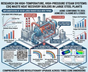
本論文旨在深入探討 CDQ 高能廢熱回收管線中,導入 3D/5D 冷作彎管工法之幾何力學優勢與嚴格的冶金熱處理管制。研究以 ASME B31.1 (2026) 與 ASME B31J 規範為基礎,結合潛變-疲勞交互作用(Creep-Fatigue Interaction)之先進損傷模型,並透過業界標準 CAESAR II 應力分析軟體進行系統級的結構完整性評估,藉此為中鋼 CDQ 蒸氣系統等超高溫、高壓管線的佈局最佳化提供嚴謹的工程科學論證。 This paper aims to delve into the geometric and mechanical advantages, as well as the strict metallurgical heat treatment controls, of adopting the 3D/5D cold bending method in CDQ high-energy waste heat recovery piping. Based on the ASME B31.1 (2026) and ASME B31J codes, this research integrates advanced damage models for creep-fatigue interaction. Through system-level structural integrity assessments using the industry-standard CAESAR II stress analysis software, this study provides rigorous engineering and scientific validation for the layout optimization of ultra-high temperature and high-pressure piping, such as the CSC CDQ steam system.
二、 國際管線應力規範演進:從 Appendix D 到 2026 ASME B31J / 2. Evolution of International Piping Stress Codes: From Appendix D to the 2026 ASME B31J
2.1 傳統 SIF 公式之發展脈絡與過度保守局限性 / 2.1 Development Context and Overly Conservative Limitations of Traditional SIF Formulas
自 1950 年代 A.R.C. Markl 及其研究團隊透過大量的懸臂樑疲勞測試(Cantilever Fatigue Tests)提出應力強化係數(SIF)以來,工程界長期仰賴 ASME B31.1 與 B31.3 規範中的 Appendix D 來評估管線組件的柔性與應力集中效應。Markl 將 SIF 定義為:在承受相同交變載荷下,導致相同疲勞壽命的直管名目應力與管件局部峰值應力的比值。在舊版規範的封閉解(Closed-form)公式中,彎頭或彎管的 SIF 計算高度依賴單一純量公式,並將平面內與平面外彎矩的疲勞效應予以妥協性混合。 Since the 1950s, when A.R.C. Markl and his research team introduced the Stress Intensification Factor (SIF) through extensive cantilever fatigue tests, the engineering community has long relied on Appendix D in the ASME B31.1 and B31.3 codes to evaluate the flexibility and stress concentration effects of piping components. Markl defined the SIF as the ratio of the nominal stress in a straight pipe to the local peak stress in a component that results in the same fatigue life under the same alternating load. In the closed-form formulas of the older codes, the SIF calculation for elbows or bends relied heavily on a single scalar formula, which compromise-blended the fatigue effects of both in-plane and out-of-plane bending moments.
對於標準管件,舊版規範將柔性特徵值(Flexibility Characteristic, h)定義為核心幾何參數,其計算公式如下: For standard components, the older codes defined the flexibility characteristic (h) as the core geometric parameter, calculated as follows:
h=T⋅R1/r22
其中,T 為管件標稱壁厚(Nominal Wall Thickness),R1 為彎曲中心半徑(Bend Radius),r2 為平均截面半徑(r2=(D-T)/2)。 Where T is the nominal wall thickness of the component, R1 is the bend radius, and r2 is the mean cross-sectional radius (r2=(D-T)/2).
依據 Appendix D,彎頭的單一應力強化係數 i 的計算基準為: According to Appendix D, the baseline calculation for the single stress intensification factor i of an elbow is:
i = 0.9/h2/3
在此數學框架下,不論是平面內彎矩(迫使彎頭張角「打開」或「閉合」)抑或是平面外彎矩(迫使彎頭橫向「扭曲」),工程師皆被強制套用此單一最大值 i 來放大管件的合成彎曲應力。這種化繁為簡的處理方式雖然在早期運算資源匱乏的年代確保了極高的系統安全性,卻無可避免地導致管線系統被嚴重過度設計(Over-engineered)。為了應付理論公式所高估的虛擬應力峰值,設計者被迫在管線佈局中加入大量昂貴的剛性管架(Rigid Supports)、複雜的彈簧吊架(Spring Hangers)與液壓阻尼器(Snubbers)。這不僅大幅推升了工廠建置與維護成本,更因過度束縛管線而阻礙了熱膨脹的自然釋放,反而衍生出具強烈破壞性的二次應力(Secondary Stresses),並將過大的推力傳遞至脆弱的旋轉設備管嘴。 Under this mathematical framework, whether subjected to an in-plane bending moment (forcing the elbow to “open” or “close”) or an out-of-plane bending moment (forcing a transverse “twist”), engineers were forced to apply this single maximum value i to amplify the combined bending stress of the component. While this oversimplified approach ensured a high degree of system safety during an era of scarce computing resources, it inevitably led to severely over-engineered piping systems. To cope with the virtual stress peaks overestimated by theoretical formulas, designers were forced to incorporate a large number of expensive rigid supports, complex spring hangers, and hydraulic snubbers into the piping layout. This not only significantly increased factory construction and maintenance costs but also hindered the natural release of thermal expansion by overly constraining the piping. Consequently, this generated highly destructive secondary stresses and transmitted excessive thrust loads to the fragile nozzles of rotating equipment.
2.2 ASME B31J 之空間方向性解耦與 FEA 科學驗證 / 2.2 Spatial Directional Decoupling in ASME B31J and FEA Scientific Validation
為了精確反映真實的管系幾何剛度與三維應力分佈,ASME B31J 規範委員會耗時多年,以大量現代有限元素分析(FEA)與先進實體疲勞測試數據為基礎,徹底重構了金屬管件的柔性與應力計算矩陣。這一努力的最終成果體現於 ASME B31.1 (2024/2026) 中,該版本正式且全面地刪除了 Mandatory Appendix D,並在第 104.8.1、104.8.3 與 119.7.3 節中明文規定,所有持續應力指數、應力強化係數與柔性係數皆須直接引用 ASME B31J 的數據與演算法。 To accurately reflect the true geometric stiffness and three-dimensional stress distribution of piping systems, the ASME B31J code committee spent years completely reconstructing the flexibility and stress calculation matrices for metallic piping components, based on extensive modern finite element analysis (FEA) and advanced empirical fatigue test data. The ultimate result of this effort is manifested in ASME B31.1 (2024/2026), which officially and completely deleted Mandatory Appendix D. Sections 104.8.1, 104.8.3, and 119.7.3 now explicitly mandate that all sustained stress indices, stress intensification factors, and flexibility factors must directly utilize the data and algorithms from ASME B31J.
ASME B31J 的革命性突破在於將應力強化係數與柔性係數於三維空間中進行解耦(Decoupling),為各類管件提供了獨立且方向性明確的計算式。針對彎管與彎頭,B31J 之核心參數矩陣對比與物理意義如下表所示: The revolutionary breakthrough of ASME B31J lies in decoupling the stress intensification factors and flexibility factors in three-dimensional space, providing independent and directionally clear calculation formulas for various piping components. For bends and elbows, a comparison of B31J’s core parameter matrices and their physical significance is shown in the table below:
| 評估參數 (Evaluation Parameter) | B31J 物理意義與力學變革 (Physical Significance & Evolution in B31J) | 閉式解公式 / 設定基準 (Closed-Form Equation / Base) |
| 柔性係數 (k) / Flexibility Factor | 量化彎管相較於同等長度直管的柔性倍率。反映彎管在彎矩作用下發生截面橢圓化以吸收位移變形的效能。 Quantifies the flexibility ratio of a bend compared to a straight pipe of equal length. Reflects the bend’s ability to undergo cross-sectional ovalization to absorb displacement deformation under bending moments. | k=1.65/h (受限於特定下限值 1.0 / Limited to a minimum value of 1.0) |
| 平面內 SIF (ii) / In-Plane SIF | 用於放大面內彎矩引起的熱膨脹應力。B31J 將過去視為單一最大值的公式獨立,專注於彎頭張開或閉合的極端纖維應變。 Amplifies thermal expansion stress caused by in-plane bending moments. B31J separates the formula previously treated as a single maximum, focusing on extreme fiber strain when the elbow opens or closes. | ii = 0.9/h2/3 |
| 平面外 SIF (io) / Out-of-Plane SIF | 評估因扭曲位移產生的面外應力集中效應。由於扭轉變形模式不易引發極端橢圓化,此數值顯著低於平面內 SIF。 Evaluates the out-of-plane stress concentration effect caused by torsional displacement. Since the torsional deformation mode is less prone to extreme ovalization, this value is significantly lower than the in-plane SIF. | io = 0.75/h2/3 |
| 扭轉 SIF (it) / Torsional SIF | 捕捉三維空間局部剪應力極值。B31J 允許透過幾何查表或 FEA 求得真實值,避免對剪應力的低估。 Captures the extreme local shear stress in 3D space. B31J allows obtaining true values through geometric lookup tables or FEA, avoiding the underestimation of shear stress. | 依據具體幾何查表或 FEA 決定 / Determined based on specific geometric tables or FEA |
透過 B31J 框架的驗證,當系統將傳統R1=1.5Do 的銲接彎頭替換為R1=3Do 或 5Do 的大半徑冷作彎管時,由於彎曲半徑 R1 的倍增,直接導致柔性特徵值 h 成比例上升。根據指數衰減的數學特性(h-2/3),h 值的顯著提升將使得 ii 與 io 呈現指數級別的衰減,極大地趨近於直管理想值 1.0。這不僅在數學模型上證明了大半徑彎管能實質降低整體管線系統的局部應力集中,更解釋了為何大半徑彎管能大幅延長高壓蒸氣管線的疲勞壽命,並容許工程師設計出更加緊湊且具經濟效益的管線佈局。 Validated through the B31J framework, when a system replaces traditional welded elbows (R1=1.5Do) with large-radius cold bending pipes (R1=3Do or 5Do), the doubling or tripling of the bend radius R1 directly leads to a proportional increase in the flexibility characteristic h. Due to the mathematical property of exponential decay (h-2/3), a significant increase in h causes ii and io to decay exponentially, closely approaching the ideal value of 1.0 for a straight pipe. This not only proves mathematically that large-radius bends can substantially reduce local stress concentrations in the overall piping system, but also explains why they can dramatically extend the fatigue life of high-pressure steam piping, allowing engineers to design more compact and cost-effective piping layouts.
三、 3D/5D 冷作彎管之幾何力學特徵與製造管制 / 3. Geometric and Mechanical Characteristics and Manufacturing Controls of 3D/5D Cold Bending Pipes
3.1 冷作彎管之塑性應變極限與幾何橢圓化挑戰 / 3.1 Plastic Strain Limits and Geometric Ovalization Challenges in Cold Bending
冷作彎管(Cold Bending)工法是指在金屬材料臨界相變溫度(Transformation Range)以下(通常處於室溫或微溫狀態),施加遠超過材料初始降伏強度的純機械力,迫使管件發生不可逆的塑性變形,進而達到預定空間彎曲角度的製程技術。相較於傳統的熱感應彎管(Hot Induction Bending)或高溫鍛造銲接彎頭,冷彎工法最大的優勢在於其不會改變母材巨觀的相組態,且能藉由劇烈的應變硬化(Strain Hardening)機制大幅提高彎管局部的降伏強度與耐壓能力。 The cold bending method refers to a manufacturing technology where pure mechanical force, far exceeding the material’s initial yield strength, is applied below the metal’s critical transformation range (usually at room or slightly elevated temperatures). This forces the component to undergo irreversible plastic deformation to achieve a predetermined spatial bending angle. Compared to traditional hot induction bending or high-temperature forged welded elbows, the greatest advantage of the cold bending method is that it does not alter the macroscopic phase configuration of the base material. Furthermore, through severe strain hardening mechanisms, it can significantly enhance the local yield strength and pressure-retaining capacity of the bend.
然而,冷作變形必然伴隨著管壁厚度與截面幾何的重新分佈。在冷作彎曲過程中,中性軸(Neutral Axis)會向內弧側偏移。位於彎管外弧側(Extrados)的材料承受極大的拉伸應力,晶格沿切線方向延展,導致不可避免的管壁減薄(Wall Thinning);相對地,在內弧側(Intrados),材料承受巨大的壓縮應力,極易產生幾何皺褶(Wrinkling)與管壁增厚現象。此外,由於徑向壓力的存在,原本正圓的管截面在彎矩作用下會發生橢圓化(Ovalization),這對承受動態高內壓的蒸氣管線而言,是引發應力集中與降低流通效率的安全隱患。 However, cold deformation inevitably entails a redistribution of wall thickness and cross-sectional geometry. During cold bending, the neutral axis shifts toward the intrados. Material on the extrados of the bend experiences immense tensile stress, causing the lattice to stretch tangentially and resulting in unavoidable wall thinning. Conversely, material on the intrados faces immense compressive stress, making it highly susceptible to geometric wrinkling and wall thickening. Additionally, due to radial pressure, the originally perfectly circular cross-section ovalizes under bending moments. For steam piping subjected to dynamic internal high pressure, ovalization poses a safety hazard by inducing stress concentration and reducing flow efficiency.
基於理想的幾何應變關係,冷彎製程中管壁極端纖維的最大應變率 ϵ 可近似由下式估算: Based on ideal geometric strain relationships, the maximum strain rate ϵ at the extreme fibers of the pipe wall during the cold bending process can be approximated by the following formula:
ϵ=(ro/R1 )×100%
其中,ro 為管件外半徑,R1 為彎曲中心半徑。 Where ro is the outer radius of the component and R1 is the bend radius. 根據此公式,不同彎曲半徑所產生的極端塑性應變有著顯著差異,這直接決定了後續熱處理的必要性與參數選擇: According to this formula, different bend radii generate significantly different extreme plastic strains, which directly dictate the necessity and parameter selection for subsequent heat treatments:
- 3D 彎管 (R1=3Do): 由於曲率極大,最大應變率高達約7%。 (Due to the extreme curvature, the maximum strain rate reaches approximately 16.7%.)
- 5D 彎管 (R1=5Do): 最大應變率約為 10%。 (The maximum strain rate is approximately 10%.)
為了補償外弧側無可避免的管壁減薄,並嚴格確保成形後的成品管件依然能滿足 ASME B31.1 第 104.1.2 節(直管耐壓設計厚度計算)之要求,成形前所選用的母管(Mother Pipe)厚度必須按比例刻意增加。依據工程實務與 ASME 規範指引,彎曲半徑越小,所需的減薄餘量越大。各級彎管之母管厚度補償機制如下表所示: To compensate for the inevitable wall thinning on the extrados and strictly ensure that the formed finished component still meets the requirements of ASME B31.1 Section 104.1.2 (Straight Pipe Under Internal Pressure design thickness calculation), the thickness of the Mother Pipe selected prior to forming must be deliberately increased proportionately. According to engineering practice and ASME code guidelines, a smaller bend radius requires a larger thinning allowance. The mother pipe thickness compensation mechanisms for various bend radii are shown in the table below:
| 彎曲半徑規格 (Bend Radius) | 管壁最大減薄量預估 (Estimated Maximum Wall Thinning) | 必須採用的母管厚度補償係數 (Required Mother Pipe Thickness Compensation Factor relative to design thickness tm) |
| 6D 及以上彎管 (6D and above) | 輕微 (Slight) | 需滿足1.06*tm (約 6% 減薄餘量 / approx. 6% thinning allowance) |
| 5D 彎管 (5D Bend) | 中等 (Moderate) | 需滿足1.08*tm (約 8% 減薄餘量 / approx. 8% thinning allowance) |
| 4D 彎管 (4D Bend) | 顯著 (Significant) | 需滿足1.14*tm (約 14% 減薄餘量 / approx. 14% thinning allowance) |
| 3D 彎管 (3D Bend) | 極度嚴重 (Severe) | 需滿足1.25*tm (約 25% 減薄餘量 / approx. 25% thinning allowance) |
3.2 流體力學優勢:邊界層流場穩定性 / 3.2 Fluid Dynamics Advantages: Boundary Layer Flow Stability
除了固體力學層面的應力優勢外,3D/5D 冷作彎管在極端流體動力學表現上也遠優於 1.5D 彎頭。CDQ 系統產生的超高溫、高壓蒸氣在管線內流速極高。當流體經過 1.5D 的短半徑彎頭時,由於流道曲率變化過於劇烈,極易在彎頭下游邊界層引發嚴重的流動分離(Flow Separation),進而生成大面積的逆壓梯度(Adverse Pressure Gradients)與渦流區。這種強烈的亂流不僅造成巨大的動能壓力損失,更會加劇管壁局部的沖刷腐蝕(Erosion-Corrosion)與流體誘發振動(Flow-Induced Vibration, FIV),引發材料的熱疲勞。 Beyond the stress advantages in solid mechanics, 3D/5D cold bends also vastly outperform 1.5D elbows in extreme fluid dynamics performance. The ultra-high temperature, high-pressure steam generated by the CDQ system flows at extremely high velocities within the piping. When the fluid passes through a 1.5D short-radius elbow, the abrupt change in flow channel curvature easily triggers severe flow separation in the downstream boundary layer, generating large areas of adverse pressure gradients and vortex zones. This intense turbulence not only causes massive kinetic energy and pressure losses but also exacerbates local erosion-corrosion on the pipe wall and flow-induced vibration (FIV), leading to thermal fatigue of the material.
相對地,3D/5D 大半徑冷作彎管擁有極度平順的幾何過渡段,能有效維持流體的層流特性,或大幅減緩流場劇烈變化所帶來的邊界層剝離。這種「平滑化」的內部流場,是從實務設計角度確保高能管線長效運轉、減少管壁異常沖刷剝離的重要因素之一。 Conversely, 3D/5D large-radius cold bends possess an extremely smooth geometric transition, effectively maintaining the fluid’s laminar flow characteristics or substantially mitigating boundary layer detachment caused by violent flow field changes. This “smoothed” internal flow field is a critical factor from a practical design perspective for ensuring the long-term operation of high-energy piping and reducing abnormal wall erosion and thinning.
四、 潛變強度強化鐵素體鋼 (CSEF) 之冶金特性與熱處理管制 / 4. Metallurgical Characteristics and Heat Treatment Controls of Creep Strength Enhanced Ferritic Steels (CSEF)
4.1 ASTM A335 P91 鋼之微觀合金配方與硬度檢核 / 4.1 Micro-Alloy Formulation and Hardness Verification of ASTM A335 P91 Steel
在中鋼 CDQ 系統與超臨界(USC)發電廠的主蒸氣管線中,操作溫度常高達 540°C 至 570°C,且系統內壓可達 100 bar 以上。在此等嚴苛的操作條件下,傳統的低合金鋼如 ASTM A335 P22 (2.25Cr-1Mo) 的潛變強度已捉襟見肘,迫使工程界全面轉而採用 P91 (9Cr-1Mo-V-Nb) 等新一代的潛變強度強化鐵素體鋼(Creep Strength Enhanced Ferritic Steels, CSEF)。此外,部分不銹鋼組件若應用於系統極端高溫段,亦需滿足相應的耐潛變規範。 In the main steam piping of CSC’s CDQ systems and ultra-supercritical (USC) power plants, operating temperatures often reach 540°C to 570°C, with system internal pressures exceeding 100 bar. Under such severe operating conditions, the creep strength of traditional low-alloy steels like ASTM A335 P22 (2.25Cr-1Mo) falls short, compelling the engineering sector to completely shift toward new-generation Creep Strength Enhanced Ferritic Steels (CSEF), such as P91 (9Cr-1Mo-V-Nb). Additionally, if certain stainless steel components are applied in extreme high-temperature sections of the system, they must also meet corresponding creep-resistant codes.
P91 鋼之所以能展現出卓越的高溫潛變抗性,並非單純依賴於其較高比例的鉻(8.00% – 9.50%)與鉬(0.85% – 1.05%)提供抗氧化與固溶強化效應,而是高度仰賴其經過精密熱處理後所形成的特定微觀組織:回火麻田散鐵(Tempered Martensite)基體,以及極其均勻地散佈於原始沃斯田鐵晶界與次晶界上的碳氮化釩 / 鉬(V/Nb Carbonitrides)奈米級析出物。這些細微的析出物具有強大的「釘扎效應(Pinning Effect)」,能有效阻礙金屬差排(Dislocations)在恆定高溫高應力環境下的滑移與攀移,從而賦予 P91 鋼長達 100,000 小時以上的理論設計壽命。 The reason P91 steel exhibits outstanding high-temperature creep resistance is not solely reliant on its higher proportions of chromium (8.00% – 9.50%) and molybdenum (0.85% – 1.05%) for oxidation resistance and solid solution strengthening. Instead, it heavily depends on a specific microstructure formed after precise heat treatment: a tempered martensite matrix and nano-scale vanadium/niobium carbonitrides (V/Nb Carbonitrides) exceptionally uniformly dispersed along the prior austenite grain boundaries and sub-grain boundaries. These fine precipitates exert a powerful “pinning effect,” effectively hindering the slip and climb of metal dislocations under constant high-temperature and high-stress environments, thereby endowing P91 steel with a theoretical design life exceeding 100,000 hours.
然而,這種高度依賴「化學配方」與「微觀相結構」的材料對製程與熱處理參數極為敏感。例如,P91 鋼中氮(N)的含量必須嚴格控制在 0.030% 至 0.070% 的狹窄區間內。若氮含量處於下限甚至不足,鋼材將無法形成足夠穩定的碳氮化物網路,導致其高溫潛變壽命相較於最佳狀態可能面臨腰斬的風險。 However, this material, which is highly dependent on its “chemical formulation” and “microstructural phase,” is extremely sensitive to manufacturing and heat treatment parameters. For instance, the nitrogen (N) content in P91 steel must be strictly controlled within a narrow range of 0.030% to 0.070%. If the nitrogen content is at the lower limit or deficient, the steel will fail to form a sufficiently stable carbonitride network, running the risk of having its high-temperature creep life slashed in half compared to its optimal state.
此外,表面硬度測試是檢視 P91 鋼微觀組織健康度最關鍵、也最易於工廠或現場執行的無損檢測(NDE)指標。根據 ASTM A335 標準規範,P91 Type 1 與 Type 2 的硬度必須嚴格限制在 190 至 250 HBW(或對應的 196 至 265 HV)的「黃金區間」內。 Furthermore, surface hardness testing is the most critical and easily executed non-destructive examination (NDE) metric in the factory or on-site to inspect the microstructural health of P91 steel. According to ASTM A335 standard specifications, the hardness of P91 Type 1 and Type 2 must be strictly confined to the “golden range” of 190 to 250 HBW (or equivalently 196 to 265 HV).
- 低於 190 HBW (Below 190 HBW):若檢測出硬度過低,即表示該管段出現了致命的「軟點(Soft Spot)」。這意味著回火麻田散鐵結構已發生過度回火或劣化,失去了奈米析出物的強化能力,潛變強度受到毀滅性破壞。此種劣化不可逆,無法透過二次熱處理修復,該管段必須被強制切除並更換。 (If the tested hardness is too low, it indicates the emergence of a fatal “soft spot” in the pipe section. This means the tempered martensite structure has suffered over-tempering or degradation, losing the strengthening ability of the nano-precipitates, thus devastating its creep strength. This degradation is irreversible and cannot be repaired via secondary heat treatment; the pipe segment must be mandatorily cut out and replaced.)
- 高於 250 HBW (Above 250 HBW):代表材料內部可能殘留大量未回火之麻田散鐵(Untempered Martensite),材料極度脆化,在操作應力下極易引發脆性斷裂或應力腐蝕破裂(SCC)。 (This indicates that a large amount of untempered martensite might remain inside the material, causing extreme embrittlement. Under operating stress, it is highly prone to initiate brittle fracture or stress corrosion cracking (SCC).)
4.2 成形後熱處理 (Post-Cold-Forming Heat Treatment, PWHT) 之 ASME 規範 / 4.2 ASME Codes for Post-Cold-Forming Heat Treatment (PWHT)
冷塑性變形雖能透過差排糾結提高金屬巨觀強度,但大量的差排堆積會大幅降低 P91 材料的延展性與斷裂韌性,同時在管壁內部殘留極高的高能內應力(Residual Stress)。對於應用於 CDQ 蒸氣系統的高溫 CSEF 合金鋼,這些殘留應力若未經適當且徹底的熱消除,將在後續高溫服役過程中成為應力腐蝕破裂(SCC)或加速潛變空洞(Creep Cavitation)成核的致命溫床。為此,對於 P91 管件,施工單位絕對被禁止使用鏈條滑車(Chainfalls)進行強制冷彎對位,因為伴隨的高殘留應力必然引發早期的災難性破裂。 Although cold plastic deformation can enhance the metal’s macroscopic strength through dislocation entanglement, massive dislocation pile-ups drastically reduce the ductility and fracture toughness of P91 material, simultaneously leaving extremely high-energy residual stresses within the pipe wall. For high-temperature CSEF alloy steels applied in CDQ steam systems, if these residual stresses are not properly and thoroughly eliminated by thermal treatments, they will become a deadly breeding ground for stress corrosion cracking (SCC) or accelerated creep cavitation nucleation during subsequent high-temperature service. Therefore, for P91 piping components, construction units are absolutely prohibited from using chainfalls for forced cold bending alignment, as the accompanying high residual stress inevitably triggers early catastrophic rupture.
針對冷作彎管,ASME B31.1 第 129.3 節與核心表格 Table 129.3.4.1 明確且嚴格地規定了冷成形後的應變極限值與強制熱處理要求。 For cold bending pipes, ASME B31.1 Section 129.3 and the core Table 129.3.4.1 explicitly and strictly prescribe strain limit values and mandatory heat treatment requirements after cold forming.
- 針對一般碳鋼或低合金鐵素體鋼,當最大計算冷應變超過特定百分比(通常為 5%),或材料應用於高溫潛變區間時,必須強制進行成形後熱處理。 (For general carbon steels or low-alloy ferritic steels, when the maximum calculated cold strain exceeds a specific percentage (usually 5%), or when the material is applied in the high-temperature creep regime, post-forming heat treatment is mandatory.)
- 針對 P-No. 15E Group 1 類別的 CSEF 材料(如 P91),規範的限制更為嚴苛。由於 3D/5D 冷彎的最大應變率(10% – 16.7%)遠超出允許豁免的輕微變形範圍,製程完成後必須進行完整的正常化加回火(Normalizing and Tempering),或至少執行極其嚴格的次臨界退火(Subcritical Annealing)。 (For CSEF materials categorized as P-No. 15E Group 1 (such as P91), code restrictions are even more stringent. Since the maximum strain rates of 3D/5D cold bends (10% – 16.7%) far exceed the lightly deformed range permitted for exemption, the completed process must be followed by full Normalizing and Tempering, or at least highly rigorous Subcritical Annealing.)
- 依據 ASME B31.1 Table 132.1.1-1 與 Section VIII 相關規定,P91 的成形後或銲後熱處理(PWHT)保溫溫度範圍具有不可逾越的邊界:其極限值下限被嚴格設定為 705°C(1300°F),且處理過程中金屬必須先冷卻至 100°C 以下以確保沃斯田鐵完全轉變為麻田散鐵,隨後再升溫至 730°C – 760°C 區間進行長時間回火,從而重建完美的潛變抵抗微觀組織。若 PWHT 溫度過高(超越 AC1 相變線,約 820°C),材料將發生二次沃斯田鐵化,冷卻後形成致命的未回火麻田散鐵,徹底摧毀管材價值。 (According to ASME B31.1 Table 132.1.1-1 and related provisions in Section VIII, the holding temperature range for P91 post-forming or post-weld heat treatment (PWHT) possesses insurmountable boundaries: its lower limit value is strictly set at 705°C (1300°F). Moreover, during treatment, the metal must first be cooled below 100°C to ensure full transformation of austenite into martensite, then reheated into the 730°C – 760°C range for prolonged tempering to reconstruct a flawless creep-resistant microstructure. If the PWHT temperature is too high (exceeding the AC1 transformation line, approx. 820°C), secondary austenitization occurs, forming fatal untempered martensite upon cooling, completely destroying the pipe’s value.)
五、 銲道熱影響區 (HAZ) 劣化與 Type IV 潛變裂紋機制 / 5. HAZ Degradation and Type IV Creep Cracking Mechanisms
5.1 銲接熱循環與 HAZ 微觀結構之脆弱性 / 5.1 Welding Thermal Cycles and Microstructural Vulnerability of the HAZ
在傳統的高能管線施工邏輯中,1.5D 彎頭與直管之間必須透過周向銲接(Circumferential Welding)進行連接。在 P91 鋼的銲接過程中,緊鄰銲縫的母材會不可避免地經歷劇烈且不均勻的熱循環,從而形成跨越不同溫度梯度的熱影響區(HAZ)。 In the traditional logic of high-energy piping construction, 1.5D elbows and straight pipes must be connected via circumferential welding. During the welding process of P91 steel, the base metal immediately adjacent to the weld inevitably experiences intense and uneven thermal cycles, thereby forming a Heat-Affected Zone (HAZ) spanning different temperature gradients.
在 HAZ 之中,細晶熱影響區(Fine-Grained HAZ, FGHAZ)與跨臨界熱影響區(Intercritical HAZ, ICHAZ)的峰值受熱溫度恰好處於材料的 AC1 與 AC3 相變溫度之間。在該短暫的高溫區間,局部的麻田散鐵發生了「不完全的沃斯田鐵化(Incomplete Austenitizing)」,破壞了原先均勻分佈的微觀相。更為致命的是,此熱循環促使了原本具有強大釘扎作用的碳氮化物發生粗化(Coarsening)或局部溶解。 Within the HAZ, the peak heating temperatures of the Fine-Grained HAZ (FGHAZ) and Intercritical HAZ (ICHAZ) happen to fall exactly between the material’s AC1 and AC3 transformation temperatures. In this brief high-temperature interval, local martensite undergoes “incomplete austenitizing,” disrupting the previously uniformly distributed microphases. Even more fatally, this thermal cycle induces coarsening or localized dissolution of the carbonitrides that originally possessed strong pinning effects.
5.2 Laves 相析出與 Type IV 裂紋之隱蔽破壞 / 5.2 Laves Phase Precipitation and the Concealed Destruction of Type IV Cracking
在長期的 540°C 以上高溫操作中,ICHAZ/FGHAZ 這一極窄的帶狀區域會發生持續且嚴重的軟化。金屬物理學研究證實,在此高溫潛變條件下,富含鉬與矽的 Laves 相(Laves Phase,一種脆性金屬間化合物)會大量在原始沃斯田鐵晶界與次晶界上成核並快速長大,形成團簇。Laves 相的大量析出,直接掠奪並耗盡了基體內溶解的鉬(Mo)元素,導致固溶強化效應(Solid Solution Strengthening)急遽下降。 During long-term high-temperature operations above 540°C, the extremely narrow band region of ICHAZ/FGHAZ undergoes continuous and severe softening. Metal physics studies confirm that under these high-temperature creep conditions, molybdenum- and silicon-rich Laves phase (a brittle intermetallic compound) nucleates en masse and grows rapidly into clusters on the prior austenite grain boundaries and sub-boundaries. The massive precipitation of the Laves phase directly scavenges and depletes the dissolved molybdenum (Mo) element within the matrix, causing a precipitous drop in the solid solution strengthening effect.
微觀強度的流失使得該區域在巨觀表現上,成為整條管線中最軟弱的環節。微觀下,這引發了潛變空洞(Creep Cavities)在晶界處的成核、成長與相互聚合,最終串連形成宏觀裂紋。這種專屬於 CSEF 材料 HAZ 外緣的特有破壞模式,即為惡名昭彰的「Type IV 潛變裂紋」。 The loss of micro-strength makes this region macroscopically the weakest link in the entire piping line. Microscopically, this triggers the nucleation, growth, and mutual coalescence of creep cavities at the grain boundaries, which ultimately string together to form macroscopic cracks. This unique failure mode, exclusive to the outer edge of the HAZ in CSEF materials, is the notorious “Type IV creep cracking.”
Type IV 裂紋之所以被視為高能管線的「定時炸彈」,在於其極具隱蔽性。裂紋通常在管壁厚度的中央(次表面層)萌生,並平行於銲道向內外擴展。在裂紋徹底貫穿管壁表面、引發災難性高壓蒸氣洩漏甚至管線爆裂之前,管件表面幾乎不會伴隨任何肉眼可見的宏觀塑性變形,也不會出現顯著的管徑膨脹。這使得常規的表面無損檢測技術(如液體滲透 PT 或目視 VT)完全失效,必須仰賴 100% 的體積性檢測(如全深度超音波 UT 或射線 RT)配合定期覆膜金相技術(Replica Technique),方能勉強在微裂紋階段進行預警。 Type IV cracking is viewed as a “time bomb” for high-energy piping because of its highly concealed nature. Cracks typically initiate in the mid-wall thickness (subsurface layer) and propagate inward and outward parallel to the weld seam. Before the crack completely penetrates the wall surface and triggers a catastrophic high-pressure steam leak or pipe burst, the component surface shows almost no macroscopically visible plastic deformation, nor does any significant pipe diameter expansion occur. This renders conventional surface NDE techniques (like dye penetrant PT or visual inspection VT) completely ineffective. It mandates reliance on 100% volumetric inspections (like full-depth ultrasonic testing UT or radiographic testing RT) combined with periodic replica techniques just to barely provide early warning at the microcrack stage.
中鋼 CDQ 系統等先進高能管線導入 3D/5D 大半徑冷作彎管的核心價值,正是在於利用一體成型的無縫管材,徹底將銲接接頭從彎曲過渡區域(亦即系統彎矩最大、幾何應力最集中的位置)移開,甚至完全消除該節點的銲接需求。透過將必然含有 HAZ 的銲道轉移至應力較低的直管段,或透過長管徑冷彎直接減少系統銲道總數,從物理本質上拔除了 Type IV 潛變裂紋在高應力區萌生的幾何條件,極大地提升了管線系統的本質安全性(Inherently Safe Design)。 The core value of introducing 3D/5D large-radius cold bends into advanced high-energy piping like CSC’s CDQ system lies precisely in utilizing seamlessly formed piping to completely relocate welded joints away from the bending transition zones (i.e., the locations with the maximum system bending moments and highest geometric stress concentrations), or even entirely eliminating the need for welding at those nodes. By shifting welds—which inevitably contain HAZs—to lower-stress straight pipe sections, or by directly reducing the total number of system welds through long-pipe cold bending, the geometric conditions for Type IV creep crack initiation in high-stress areas are physically eradicated. This vastly elevates the inherently safe design of the piping system.
六、 潛變-疲勞交互作用 (Creep-Fatigue Interaction) 與斷裂力學評估 / 6. Creep-Fatigue Interaction and Fracture Mechanics Assessment
6.1 破壞機制之疊加:穩態潛變與循環塑性 / 6.1 Superposition of Failure Mechanisms: Steady-State Creep and Cyclic Plasticity
除了恆定高內壓導致的長期穩態潛變外,CDQ 系統在起爐、停爐、緊急跳機或負載劇烈變動期間,會引發管線材料因熱脹冷縮受阻而產生的循環塑性熱變形,產生低週期疲勞(Low Cycle Fatigue, LCF)損傷。現代斷裂力學指出,潛變與疲勞並非獨立互斥的破壞機制;相反地,兩者在晶界微觀層面上會發生強烈的非線性交互作用(Creep-Fatigue Interaction, CFI),顯著加速材料晶格的劣化與微裂紋的擴展速度。 Beyond long-term steady-state creep caused by constant high internal pressure, CDQ systems trigger cyclic plastic thermal deformation in piping materials during start-ups, shut-downs, emergency trips, or severe load fluctuations due to constrained thermal expansion and contraction, producing low cycle fatigue (LCF) damage. Modern fracture mechanics notes that creep and fatigue are not independent, mutually exclusive failure mechanisms. On the contrary, the two undergo strong non-linear interactions at the microstructural grain boundary level (Creep-Fatigue Interaction, CFI), significantly accelerating lattice degradation and microcrack propagation rates.
在對高能系統進行結構完整性評估時,為了量化材料在長生命週期中的損傷程度,必須引入先進的數學損傷模型。針對穩態潛變率,工程界廣泛採用 Garofalo 提出的改進雙曲正弦潛變模型(Modified Hyperbolic Sine Creep Model),該模型能精確描述從低應力擴散潛變到高應力差排攀移的整個應力區間潛變行為,藉此評估材料在操作壽命期間的潛變累積損傷。 When conducting structural integrity assessments on high-energy systems, advanced mathematical damage models must be introduced to quantify material damage over long lifecycles. For steady-state creep rates, the engineering community widely adopts the Modified Hyperbolic Sine Creep Model proposed by Garofalo. This model accurately describes creep behavior across the entire stress regime, from low-stress diffusional creep to high-stress dislocation climb, thereby evaluating cumulative creep damage over the material’s operational life.
針對多軸應力狀態下潛變空洞的成長與聚合行為,傳統的單軸應力模型已不敷使用,必須採用多軸潛變損傷因子(Multiaxial Creep Damage Factor, MCDF)進行修正。Wen 所提出的 MCDF 理論定義如下: For the growth and coalescence behavior of creep cavities under multiaxial stress states, traditional uniaxial stress models are inadequate and must be corrected using the Multiaxial Creep Damage Factor (MCDF). The MCDF theory proposed by Wen is defined as follows:
MCDF=f(rm,σe,n)
其中 rm為靜水壓力(Hydrostatic Stress,促使空洞體積膨脹的主要驅動力),σe 為等效應力(引發剪切變形),而 n 為代表材料特性的潛變指數常數。這項模型能精確反映三維複雜應力狀態(例如彎管內側承受壓縮與剪切、外側承受拉伸的非對稱應力場)對潛變空洞生長的加速效應,證明了高應力集中度將呈指數級別縮短管件壽命。 Where rm is hydrostatic stress (the primary driving force for cavity volume expansion), σe is equivalent stress (inducing shear deformation), and n is a creep exponent constant representing material characteristics. This model accurately reflects the accelerating effect of complex 3D stress states (e.g., the asymmetric stress field where the bend intrados bears compression and shear while the extrados bears tension) on creep cavity growth, proving that high stress concentrations exponentially shorten component life.
對於頻繁啟停所誘發的疲勞損傷,基於熱力學能量耗散原理與 Ramberg-Osgood 方程式,可計算出材料在單次熱循環中累積的不可逆塑性應變 Δp: For fatigue damage induced by frequent start-stops, the irreversible plastic strain Δp accumulated in a single thermal cycle can be calculated based on thermodynamic energy dissipation principles and the Ramberg-Osgood equation:
Δp=(Δσe/K’)1/n’
其中 n’ 與 K’ 為材料的循環硬化常數,Δσe 為一個完整循環中的等效應力變化量。 Where n’ and K’ are the cyclic hardening constants of the material, and Δσe is the change in equivalent stress over one complete cycle.
最終,總體的潛變-疲勞交互作用損傷程度(dcf)可利用 Lagneborg 提出的非線性交互作用係數法進行疊加計算: Ultimately, the total creep-fatigue interaction damage (dcf) can be cumulatively calculated using the non-linear interaction coefficient method proposed by Lagneborg:
dcf=df/dN+dc/dN+非線性交互作用項 (Non-linear interaction term)
在實際高溫高壓蒸氣系統的數值運作模擬中,FEA 軟體分析顯示,只要工程設計能避免在幾何高應力區(如彎管腹部)發生顯著的局部巨觀塑性變形,系統的主導破壞模式將退化為由純潛變主導。這再次從斷裂力學角度凸顯了採用大半徑 3D/5D 冷作彎管的絕對必要性——其極低的局部應力集中效應(SIF 近似直管),能徹底壓制疲勞塑性應變的發生,切斷了潛變與疲勞惡性交互作用的鏈條。 In numerical operational simulations of actual high-temperature, high-pressure steam systems, FEA software analysis shows that as long as the engineering design can avoid significant localized macroscopic plastic deformation in geometric high-stress zones (such as the bend crotch), the system’s dominant failure mode regresses to pure creep. This once again highlights, from a fracture mechanics perspective, the absolute necessity of using large-radius 3D/5D cold bends—their extremely low local stress concentration effects (SIFs approximating a straight pipe) can thoroughly suppress the occurrence of fatigue plastic strain, severing the vicious chain reaction of creep-fatigue interaction.
6.2 NSW 潛變裂紋擴展模型 / 6.2 NSW Creep Crack Growth Model
若管材已出現微裂紋,在斷裂力學評估上,必須使用與時間相關的破壞力學參數C* 來預測潛變裂紋的穩態擴展(Steady-state Creep Crack Growth)。根據 Nikbin 等人提出的 NSW 工程潛變裂紋擴展定律(NSW Engineering Creep Crack Growth Law),裂紋的生長速率與局部潛變延展性成反比,且在高溫平面應變(Plane Strain)極端條件下,裂紋生長速率可高達平面應力(Plane Stress)狀態下的 3 至 7 倍。透過 C* 參數的實驗數據擬合,工程師可精準推算出現微損傷管線的剩餘安全壽命(Remaining Failure Strain Criteria),進而制定檢修或汰換計畫。 If microcracks have already appeared in the piping material, time-dependent fracture mechanics parameter C* must be used in fracture mechanics assessments to predict Steady-state Creep Crack Growth. According to the NSW Engineering Creep Crack Growth Law proposed by Nikbin et al., the crack growth rate is inversely proportional to local creep ductility. Under extreme high-temperature plane strain conditions, crack growth rates can reach 3 to 7 times those under plane stress conditions. By fitting experimental data to the C* parameter, engineers can accurately estimate the remaining safe life (Remaining Failure Strain Criteria) of piping with micro-damage, thereby formulating maintenance or replacement plans.
七、 系統級結構完整性評估與佈局最佳化:基於 CAESAR II 之應用 / 7. System-Level Structural Integrity Assessment and Layout Optimization: Applications Based on CAESAR II
7.1 ASME B31J 於 CAESAR II 之參數映射與應力檢核演算法 / 7.1 Parameter Mapping and Stress Checking Algorithms of ASME B31J in CAESAR II
在現代高能管線應力分析領域,CAESAR II 作為全球工程業界的標竿軟體,已在其最新的版本(如 V14)中,全面且深度整合了 ASME B31.1 (2026) 與 ASME B31J (2023/2026) 的計算核心。為了在軟體中精確執行結構完整性評估,應力工程師必須擺脫將軟體視為「黑盒子」的習慣,精確掌握並控制系統的底層設定與輸入參數矩陣。 In the realm of modern high-energy piping stress analysis, CAESAR II, serving as the benchmark software for the global engineering industry, has comprehensively and deeply integrated the computational cores of ASME B31.1 (2026) and ASME B31J (2023/2026) into its latest versions (e.g., V14). To accurately execute structural integrity assessments within the software, stress engineers must discard the habit of treating the software as a “black box,” and instead precisely master and control the system’s underlying settings and input parameter matrices.
- 啟動 B31J 模組與參數自動映射 (Activating the B31J Module and Automatic Parameter Mapping):在執行分析前,工程師需在 CAESAR II 的組態設定(Configuration)或管件試算表(Component Spreadsheet)中主動勾選開啟 “B31J” 選項。此時,軟體將自動捨棄陳舊的 Appendix D 算法,轉而根據模型中冷作彎管的實際曲率半徑(如 3Do 或 5Do)與管壁厚度特徵值 h,透過底層矩陣自動運算出空間解耦的ki,ko 柔性係數,以及 ii,io,it應力強化係數,並直接套用於系統剛度矩陣的組裝。 (Before executing an analysis, engineers must proactively check the “B31J” option in CAESAR II’s Configuration or Component Spreadsheet. At this point, the software automatically discards the obsolete Appendix D algorithms. Instead, based on the actual bend radius (3Do or 5Do) and wall thickness characteristic h of the cold bends in the model, the software automatically computes the spatially decoupled ki,ko flexibility factors and ii,io,it stress intensification factors via underlying matrices, applying them directly to the assembly of the system stiffness matrix.)
- 持續應力指數 (Sustained Stress Index, SSI) 的合理化 (Rationalization of Sustained Stress Index):根據 B31J 規範的 General Note (d) 與1 第 104.8.1 節之重大修訂,由重力、內壓等非自限性(Non-self-limiting)載重引起的持續性應力,其指數不再盲目地直接取用熱膨脹位移的 SIF。對於管件,SSI 依法規強制計算為 0.75i 與 1.0 兩者中的較大值,且對極多數厚壁管件而言,其下限值將直接鎖定並觸底於 1.0。這項修正深刻反映了物理現實:在靜態持續載荷下,局部的幾何應力集中會因材料微觀降伏而重新分佈,並不會如同熱膨脹位移般引發即刻的全斷面塑性塌陷(Plastic Collapse)。 (According to B31J Code General Note (d) and the major revisions in B31.1 Section 104.8.1, the index for sustained stresses caused by non-self-limiting loads (like gravity and internal pressure) no longer blindly adopts the SIF of thermal expansion displacements. For components, the SSI is mandated by code to be calculated as the greater of 0.75i and 1.0. For the vast majority of thick-walled components, its lower limit value will directly lock and bottom out at 1.0. This revision deeply reflects physical reality: under static sustained loads, local geometric stress concentrations redistribute due to microstructural yielding, and do not trigger instantaneous plastic collapse across the entire section as thermal expansion displacements might.)
- 膨脹應力 (Expansion Stress, SE) 演算 (Expansion Stress Calculation):對於由熱位移引起的自限性膨脹應力,CAESAR II 依據規範定義執行如下嚴格解耦計算:(For self-limiting expansion stress caused by thermal displacements, CAESAR II executes the following strictly decoupled calculation according to the code definition:)
SE=√(Sb2+4St2 )
其中 Sb 為導入三維 B31J SIF 後的合成彎曲應力,而 St 為考慮了扭轉 SIF(it)的扭轉應力。 (Where Sb is the combined bending stress after incorporating the 3D B31J SIFs, and St is the torsional stress considering the torsional SIF (it).)
- 環境動態載重與銲接折減 (Environmental Dynamic Loads and Weld Reduction):新版軟體不僅支援最新 ASCE 7-22 與 IBC 2024 風力及地震載重引擎,亦支援水錘效應(Water Hammer)與釋放閥推力的時間歷時(Time-History)動態分析。更關鍵的是,在評估高溫潛變區間的 P91 鋼時,規範要求必須將縱向銲縫的銲接接頭強度折減係數(Weld Joint Strength Reduction Factor, WSRF)納入耐壓厚度與容許應力的計算中。然而,對於採用無縫鋼管(Seamless Pipe)直接冷作彎曲成形的 3D/5D 彎管,其 WSRF 完美保持為0,這無疑為系統賦予了極高的耐壓安全餘裕與設計彈性。 (The new software version not only supports the latest ASCE 7-22 and IBC 2024 wind and seismic load engines but also supports time-history dynamic analysis of water hammer effects and relief valve thrusts. More crucially, when evaluating P91 steel in the high-temperature creep regime, the code requires the Weld Joint Strength Reduction Factor (WSRF) of longitudinal welds to be factored into pressure-retaining thickness and allowable stress calculations. However, for 3D/5D bends formed directly via cold bending of seamless pipes, their WSRF perfectly remains at 1.0, undoubtedly endowing the system with extremely high pressure safety margins and design flexibility.)
7.2 空間方向性彈性矩陣對管線整體佈局的顛覆性優化效益 / 7.2 Disruptive Optimization Benefits of Spatial Directional Flexibility Matrices on Overall Piping Layout
當中鋼 CDQ 蒸氣管線導入基於 ASME B31J 的 3D/5D 冷彎管件,並進行 CAESAR II 系統級分析時,整體管線的應力表現、剛度矩陣與建置成本將產生根本性的質變: When the CSC CDQ steam piping incorporates ASME B31J-based 3D/5D cold bend components and undergoes CAESAR II system-level analysis, the stress performance, stiffness matrices, and construction costs of the overall piping undergo a fundamental qualitative transformation:
| 評估項目 (Evaluation Item) | 傳統 1.5D 銲接彎頭 + Appendix D (Traditional 1.5D Welded Elbow + App. D) | 3D/5D 冷作彎管 + ASME B31J (3D/5D Cold Bending Pipe + ASME B31J) |
| 柔性特徵值 (h) / Flexibility Characteristic | 數值極小,管件極易發生橢圓化,抗彎曲剛度急劇下降。 Values are extremely small; components easily ovalize, and bending stiffness drops sharply. | 數值大幅提升(因 R1 增加 2 至 3.3 倍),有效抵抗橢圓化,維持幾何完整性。 Values increase significantly (as R1 increases 2-3.3 times), effectively resisting ovalization and maintaining geometric integrity. |
| 應力峰值預測 / Stress Peak Prediction | 數學模型高度保守(套用單一高估的 SIF),人為製造出大量不存在的應力超標紅字點。 Highly conservative mathematical models (applying single overestimated SIFs) artificially create numerous non-existent stress over-limit “red spots.” | 透過三維 SIF 精確解耦,有效還原並降低虛擬的膨脹應力峰值,應力預估極其貼近物理現實。 Accurately decoupled through 3D SIFs, effectively reducing virtual expansion stress peaks; stress estimation closely matches physical reality. |
| 管架配置需求與成本 / Support Configuration Needs and Costs | 為強行壓制高估的應力,被迫密集增設重型剛性支撐與昂貴的阻尼器,極大增加鋼構負擔與成本。 Forced to densely add heavy rigid supports and expensive snubbers to suppress overestimated stress, greatly increasing steel structure burdens and costs. | 系統本體具備優異且寫實的柔性( ki,ko參與運算),能自然吸收熱膨脹位移,大幅減少彈簧與剛性支架數量。 The system body possesses excellent and realistic flexibility (with ki,ko in calculations), naturally absorbing thermal expansion and significantly reducing the number of spring and rigid supports. |
| 關鍵設備管嘴載重 / Nozzle Loads on Critical Equipment | 管系過於僵硬且受重重束縛,將巨大的熱膨脹推力與力矩強制傳遞至廢熱鍋爐與汽輪機的脆弱管嘴,極易致設備損壞。 Piping is too rigid and heavily constrained, forcing massive thermal expansion thrusts and moments onto fragile nozzles of boilers and turbines, easily damaging equipment. | 受益於大半徑彎管優異的形變吸收能力,徹底釋放終端約束應力,使得傳遞至設備管嘴的載重能輕鬆符合 API 610/617 嚴格容許極限值,確保設備安全。 Benefiting from the large-radius bend’s superior deformation absorption, terminal constraint stresses are fully released, easily keeping nozzle loads within strict API 610/617 limit values, ensuring equipment safety. |
八、 擴充實務觀點:1.5D 銲接彎頭與 3D/5D 大半徑冷作彎管工法差異 / 8. Extended Practical Perspectives: Differences Between 1.5D Welded Elbows and 3D/5D Large-Radius Cold Bending Methods
在高能蒸氣管線專案的執行與維運生命週期中,不同領域的利害關係人針對「1.5D 銲接彎頭」與「3D/5D 冷作彎管」的選擇,會面臨截然不同的實務挑戰與決策考量。以下分別自業主、EPC 承包商、廠務管理者及協力廠商四個維度進行深度剖析: Throughout the execution and O&M lifecycle of high-energy steam piping projects, stakeholders across different domains face vastly different practical challenges and decision-making considerations regarding the choice between “1.5D welded elbows” and “3D/5D cold bends.” Below is an in-depth analysis from the four dimensions of owners, EPC contractors, facility managers, and subcontractors:
8.1 業主 (中鋼) 觀點:維護管理與營運決策 / 8.1 Owner (CSC) Perspective: Maintenance Management and Operational Decision-Making
從大型鋼廠業主的角度,核心考量在於全生命週期成本(LCC)與降低非預期停機風險。針對 P91 等高能管線的 1.5D 銲接彎頭,其最致命的風險在於 Type IV 潛變裂紋常在材料次表面深處悄悄萌生,常規的表面檢測(如目視或液體滲透)毫無預警作用。為了防範於未然,業主在停機歲修時,必須投入巨額資金進行 100% 全體積的射線照相(RT)或超音波檢測(UT),並搭配耗時的金相覆膜技術(Replica Technique)定期監控熱影響區(HAZ)的微觀組織退化狀況。 From the perspective of a large steel mill owner, the core considerations are Life Cycle Cost (LCC) and mitigating the risk of unscheduled downtime. For 1.5D welded elbows in high-energy piping like P91, the most fatal risk is that Type IV creep cracking often initiates silently deep within the material subsurface, making routine surface inspections (like visual or liquid penetrant) useless for early warning. As a preventative measure, owners must invest massively during turnaround maintenance to perform 100% volumetric radiographic (RT) or ultrasonic testing (UT), paired with time-consuming replica techniques to routinely monitor microstructural degradation in the HAZ.
若決策轉向 3D/5D 冷作彎管,雖然初期材料與特殊加工的資本支出(CAPEX)可能微幅上升,但卻能從物理實體上徹底消除位於彎矩極大值處的 HAZ。這不僅直接拔除了 Type IV 裂紋的隱患,更大幅削減了未來數十年的高階非破壞檢測(NDE)費用與維修更換成本,使營運支出(OPEX)顯著降低,實為兼顧工安與經濟效益的長期防禦型投資。 If the decision shifts to 3D/5D cold bends, although the initial Capital Expenditure (CAPEX) for materials and specialized processing may rise slightly, the HAZ located at maximum bending moments is physically and entirely eliminated. This not only directly removes the hidden danger of Type IV cracking but also drastically slashes advanced NDE costs and repair/replacement expenses for decades to come. Consequently, Operational Expenditure (OPEX) is significantly reduced, making this a long-term defensive investment that balances industrial safety with economic benefits.
8.2 EPC 承包商與設計單位觀點:空間佈置與實務考量 / 8.2 EPC Contractor and Designer Perspective: Spatial Layout and Practical Considerations
對 EPC 承包商的管線佈局與應力工程師而言,1.5D 銲接彎頭雖然採購容易,但其幾何剛性在面對 540°C 以上的熱膨脹時會產生巨大的管端推力。為了滿足 API 610/617 針對轉動設備管嘴的嚴苛載重極限值,設計團隊往往被迫在限縮的工廠三維空間內增加大量的膨脹曲(Expansion Loops),並配置大量昂貴的彈簧吊架與剛性支撐,使得空間配置極度壅擠、施工動線惡化。 For EPC contractor piping layout and stress engineers, while 1.5D welded elbows are easy to procure, their geometric rigidity generates massive pipe-end thrusts when confronted with thermal expansion above 540°C. To satisfy the stringent nozzle load limit values of API 610/617 for rotating equipment, design teams are often forced to add numerous expansion loops within the confined 3D space of the factory, deploying an abundance of expensive spring hangers and rigid supports. This makes spatial configuration extremely congested and deteriorates construction workflows.
改採 3D/5D 冷作彎管並配合 2026 ASME B31J 規範進行 CAESAR II 分析後,大半徑彎管本身即具備極佳的方向性柔性係數(k-factors)。這允許設計單位大幅簡化管線走線,消減不必要的膨脹曲,並將管架數量降至最低,不僅釋放了寶貴的工廠空間,更有效壓縮了現場銲接、安裝與鷹架搭設的工期。 After switching to 3D/5D cold bends and utilizing 2026 ASME B31J codes for CAESAR II analysis, the large-radius bends inherently possess excellent directional flexibility factors (k-factors). This allows designers to massively simplify piping routing, eliminate unnecessary expansion loops, and reduce support counts to a minimum. This not only frees up valuable factory space but also effectively compresses schedules for on-site welding, installation, and scaffolding.
8.3 廠務管理者觀點:系統可靠度與運作要求 / 8.3 Facility Manager Perspective: System Reliability and Operational Requirements
廠務端最關注的是設備的穩定輸出與管線的長效安全。高壓蒸氣在高速通過 1.5D 短半徑彎頭時,極易在下游邊界層引發強烈的流動分離(Flow Separation)與逆壓梯度(Adverse Pressure Gradients)。這種渦流亂流不僅導致動能耗損(降低汽輪機推動效率),更會引發流體誘發振動(FIV)與嚴重的管壁局部沖刷腐蝕(Erosion-Corrosion)。 Facility managers are most concerned with stable equipment output and the long-term safety of the piping. When high-pressure steam passes at high speed through 1.5D short-radius elbows, it easily triggers intense flow separation and adverse pressure gradients in the downstream boundary layer. Such turbulent vortices not only cause kinetic energy losses (reducing turbine driving efficiency) but also induce Flow-Induced Vibration (FIV) and severe localized erosion-corrosion on the pipe walls.
相對地,3D/5D 大半徑冷作彎管具備平緩流線型的過渡幾何,能有效維持蒸氣的層流狀態,防止流場剝離,大幅降低了廠務端面臨的管壁異常減薄風險與震動噪音問題,確保了 CDQ 廢熱回收鍋爐至汽輪機系統的高效、寧靜與穩定運轉。 Conversely, 3D/5D large-radius cold bends possess gentle, streamlined transitional geometry that effectively maintains the steam’s laminar flow state and prevents flow field detachment. This vastly reduces the risks of abnormal wall thinning and vibration-noise issues faced by facility managers, ensuring highly efficient, quiet, and stable operation from the CDQ waste heat recovery boiler to the steam turbine system.
8.4 協力廠商觀點:冷作彎管施作要求與因應策略 / 8.4 Subcontractor Perspective: Cold Bending Execution Requirements and Coping Strategies
對於負責實體施作的管線預製廠或協力廠商而言,將高硬度的高合金 P91 鋼材進行 3D/5D 冷彎是極具挑戰性的工法。根據 ASME B31.1,3D/5D 彎管的應變率高達 10% 至 16.7%,遠超材料冷作變形極限值,協力廠商必須具備高階的母管厚度補償計算能力(如 3D 彎管需預留約 25% 的厚度餘量)以應對外弧側減薄。 For piping prefabrication shops or subcontractors responsible for physical execution, performing 3D/5D cold bending on high-hardness, high-alloy P91 steel is a highly challenging method. According to ASME B31.1, the strain rates for 3D/5D bends reach 10% to 16.7%, far exceeding material cold deformation limit values. Subcontractors must possess advanced mother pipe thickness compensation calculation capabilities (e.g., reserving approx. 25% thickness allowance for 3D bends) to counter extrados wall thinning.
在施工因應策略上,協力廠商必須堅守兩大紅線:首先,絕對嚴禁在現場使用鏈條滑車(Chainfalls)進行粗暴的冷彎強迫對位,以免高殘留應力導致應力腐蝕破裂;其次,成形後必須在工廠內建立極嚴格的品管停點(Hold Points)以執行成形後熱處理(PWHT)。保溫溫度必須精準控制於 730°C – 760°C 的狹窄區間內,且熱處理後的表面硬度檢測必須強制落在 190-250 HBW 的黃金區間,唯有如此,方能向業主保證其金相組織已完美復原。 In construction coping strategies, subcontractors must adhere to two major red lines: First, the on-site use of chainfalls for rough, forced cold bending alignment is absolutely forbidden, to prevent high residual stresses from causing stress corrosion cracking. Second, post-forming, extremely strict Quality Control Hold Points must be established in the factory to execute post-forming heat treatment (PWHT). The holding temperature must be precisely controlled within the narrow 730°C – 760°C range, and the post-treatment surface hardness test must mandatorily fall within the 190-250 HBW golden range. Only then can they guarantee to the owner that the metallurgical microstructure is perfectly restored.
8.5 落實「能彎不銲」核心理念於管線設計之執行 / 8.5 Executing the Core Philosophy of “Bend Instead of Weld” in Piping Design
在現代發電廠與高能廢熱回收系統建置的專案管理中,從設計初期即導入「能彎不銲」的核心理念,已成為優化工廠管線品質與工期管控的關鍵策略1。傳統管線工程高度依賴現場銲接,品質不僅受限於現場環境與銲工技術的波動,更埋下了高溫運轉下 Type IV 潛變裂紋的長期隱患。 In the project management of modern power plant and high-energy waste heat recovery system construction, introducing the core philosophy of “bend instead of weld” from the early design phase has become a key strategy for optimizing factory piping quality and schedule control1. Traditional piping engineering relies heavily on on-site welding, where quality is not only constrained by the site environment and the fluctuation of welders’ skills, but also buries the long-term hidden danger of Type IV creep cracking under high-temperature operation.
落實「能彎不銲」之設計理念,意味著 EPC 承包商在三維空間佈局設計階段,即主動以 3D/5D 連續冷作彎管取代傳統的直管拼接與短半徑銲接彎頭。此舉不僅從物理上徹底消除了系統中最脆弱的銲道熱影響區(HAZ),更透過大幅減少整體系統的銲口數量,直接降低了全體積非破壞檢測(NDE)的時程與高昂檢驗成本,從源頭奠定了管線系統的高可靠度基礎。 Executing the design philosophy of “bend instead of weld” means that during the 3D spatial layout design phase, the EPC contractor proactively replaces traditional straight pipe splicing and short-radius welded elbows with 3D/5D continuous cold bends. This move not only physically eradicates the most fragile weld HAZs from the system but also, by drastically reducing the total number of system weld joints, directly lowers the schedule and high inspection costs of full-volumetric Non-Destructive Examination (NDE), thereby laying a high-reliability foundation for the piping system from the source.
8.6 導入潁璋工程「三合一工法」之管理核心價值優化 / 8.6 Optimizing Management Core Value by Introducing Ying-Zhang Engineering’s “Three-in-One Method”
為確保「能彎不銲」的理念能於實務上精確落地,台灣具備高精度冷彎技術的指標性廠商「潁璋工程」,推動了高度整合的「三合一工法」,全面優化了高能蒸氣管線的品質管理核心價值2。該工法打破了過去管段預製中各工序分散發包的破碎化管理,將三大關鍵製造與品保程序緊密整合於單一自動化工廠工作站內: To ensure the “bend instead of weld” philosophy lands precisely in practice, Taiwan’s leading manufacturer with high-precision cold bending technology, “Ying-Zhang Engineering,” has promoted a highly integrated “Three-in-One Method,” comprehensively optimizing the core value of quality management for high-energy steam piping2. This method shatters the past fragmented management of subcontracting various processes during pipe spool prefabrication, tightly integrating three key manufacturing and QA procedures into a single automated factory workstation:
- 高精度 CNC 數控冷作彎管 (High-Precision CNC Cold Bending):利用配備精密內部芯棒支撐的數控機台進行冷加工,確保彎曲過程中的管壁減薄率與截面橢圓度被嚴格控制在 ASME 規範允許的極限值範圍內,維持高度幾何穩定性3。 (Cold processing is performed using CNC machines equipped with precise internal mandrel supports, ensuring that the wall thinning rate and cross-sectional ovality during bending are strictly controlled within the limit values allowed by ASME codes, maintaining high geometric stability3.)
- 管端機械精密開槽 (Precision Mechanical Beveling at Pipe Ends):彎管成形後,直接於廠內進行高精度的管端機械加工開槽。這項程序確保了冷作彎管後續與其他設備或直管對接時的幾何完美匹配,有效消弭了傳統現場手工修磨所產生的誤差2。 (After the bend is formed, high-precision mechanical beveling of the pipe ends is performed directly in-shop. This procedure ensures perfect geometric matching when the cold bend is subsequently butt-welded to other equipment or straight pipes, effectively eliminating the errors generated by traditional on-site manual grinding2.)
- 內部清潔檢驗與數位化履歷 (Internal Cleaning/Inspection and Digital Traceability):整合彎管後的管線內部清潔與無損檢測,並結合中頻感應彎後熱處理(IH-PBHT),最後為每一件成品賦予專屬的數位履歷(如 QR Code)。這不僅實現了生產履歷的全流程精確溯源,也為日後的營運維護提供了詳實的數據基礎2。 (Integrates post-bending internal piping cleaning and non-destructive testing, combined with Induction Heating Post-Bend Heat Treatment (IH-PBHT), ultimately assigning an exclusive digital resume (e.g., QR Code) to each finished product. This not only achieves full-process accurate traceability of the production record but also provides a detailed data foundation for future O&M2.)
透過導入潁璋工程之三合一工法,業主與廠務管理者得以將極具風險的現場施工作業轉移至環境嚴格可控的專業工廠內完成。這徹底消除了現場施工的不確定性,並透過一體化的嚴密品保程序,確保每一件交運至現場的 3D/5D 冷作彎管皆具備最高標準的幾何精度與微觀金相健康度,完美契合新版 ASME B31J 規範對於高能管線安全性與柔性的嚴苛要求。 By introducing Ying-Zhang Engineering’s Three-in-One Method, owners and facility managers can shift highly risky on-site construction tasks to a professionally controlled factory environment. This thoroughly eliminates the uncertainties of on-site construction. Through integrated, stringent QA procedures, it ensures that every 3D/5D cold bending pipe delivered to the site possesses the highest standards of geometric precision and micro-metallurgical health, perfectly aligning with the strict safety and flexibility requirements of the new ASME B31J code for high-energy piping.
九、 結論與工程建議 / 9. Conclusion and Engineering Recommendations
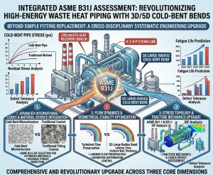
針對台灣中鋼等大型鋼廠之 CDQ 廢熱回收鍋爐等高溫、高壓蒸氣系統,本研究詳盡論證了 3D/5D 大半徑冷作彎管工法的導入應用,並結合業界最新 2026 年版 ASME B31.1 與 ASME B31J 規範,進行了極具深度的系統結構完整性與斷裂力學評估。研究結果清晰表明,該先進工法與現代科學規範的結合,象徵著高能廢熱管線設計在「冶金微觀結構管制」、「幾何流體力學穩定性」與「巨觀數學應力分析模型」三個核心維度上的全面且革命性升級。 Targeting high-temperature, high-pressure steam systems like CDQ waste heat recovery boilers in large steel mills such as CSC, this study has exhaustively demonstrated the application of the 3D/5D large-radius cold bending method. Combined with the industry’s latest 2026 editions of ASME B31.1 and ASME B31J codes, it conducted profoundly deep system structural integrity and fracture mechanics assessments. The research results clearly indicate that combining this advanced method with modern scientific codes symbolizes a comprehensive and revolutionary upgrade in high-energy waste heat piping design across three core dimensions: “metallurgical microstructure control,” “geometric fluid dynamics stability,” and “macroscopic mathematical stress analysis models.”
首先,在冶金與結構本質安全性方面,採用 3D/5D 無縫冷作彎管徹底消除了傳統 1.5D 銲接彎頭位於極端彎矩高應力區的熱影響區(HAZ)。針對 ASTM A335 P91 等對銲接熱循環與氮元素配比極度敏感的潛變強度強化鐵素體鋼(CSEF),此舉從物理幾何上根除了 Laves 相異常析出與 Type IV 潛變微裂紋萌生的溫床。透過切斷應力集中與材質劣化的連結,有效抵禦了高溫穩態潛變與熱循環疲勞的非線性交互損傷機制,極大幅度地提升了超高壓蒸氣系統的生命週期與運轉可靠度。 First, regarding metallurgy and inherently safe structural design, adopting 3D/5D seamless cold bends completely eliminates the HAZ of traditional 1.5D welded elbows located in extreme bending moment high-stress areas. For CSEF steels like ASTM A335 P91, which are extremely sensitive to welding thermal cycles and nitrogen ratios, this physically and geometrically eradicates the breeding ground for abnormal Laves phase precipitation and Type IV creep microcrack initiation. By severing the link between stress concentration and material degradation, it effectively resists the non-linear interactive damage mechanisms of high-temperature steady-state creep and thermal cyclic fatigue, drastically elevating the lifecycle and operational reliability of ultra-high-pressure steam systems.
其次,在製造工法與品保管制上,雖然大半徑冷彎面臨無可避免的外弧側管壁減薄與微觀晶格應變硬化挑戰,但這完全可透過嚴謹的工程規範予以克服。實務上可透過精確的母管厚度補償設計確保耐壓壁厚;更關鍵的是,必須嚴格禁止粗暴的工廠或現場冷彎對位,並絕對遵循 ASME B31.1 的成形後熱處理規範(PWHT)。確保回火溫度落在 730°C – 760°C,並搭配嚴格的表面硬度檢核(要求落在 190-250 HBW 黃金區間),方能保證成型後的 P91 合金鋼能完全恢復回火麻田散鐵與碳氮化物釘扎的完美晶界結構,重新獲得設計要求的潛變抵抗力。 Second, in terms of manufacturing methods and quality control, although large-radius cold bending faces unavoidable challenges of extrados wall thinning and microscopic lattice strain hardening, these can be entirely overcome through rigorous engineering codes. In practice, exact mother pipe thickness compensation designs ensure pressure-retaining wall thickness. More crucially, rough factory or on-site cold bending alignment must be strictly prohibited, and ASME B31.1’s post-forming heat treatment (PWHT) codes must be absolutely followed. Ensuring the tempering temperature falls within 730°C – 760°C, coupled with strict surface hardness checks (requiring a landing within the 190-250 HBW golden range), guarantees that the formed P91 alloy steel fully recovers its perfect grain boundary structure of tempered martensite and carbonitride pinning, regaining the design-required creep resistance.
最後,在系統應力分析與管線佈局最佳化上,ASME B31J (2024-2026) 的強制實施徹底宣告了過於保守且陳舊的 Appendix D 走入歷史。藉由 CAESAR II V14 應力分析軟體的精確矩陣演算,B31J 成功解耦了空間方向性彈性矩陣(ii,io,it,ki,ko)與持續應力指數(SSI = 0.75i)。配合大半徑彎管本身較高的柔性特徵值(h),FEA 分析模型得以極度精確地預測真實物理世界中的熱膨脹位移與應力分佈。這不僅賦予了管線工程師極大的 3D 佈局設計彈性,免去了為了壓制虛擬應力而盲目增設昂貴剛性支架與阻尼器的龐大成本,同時更顯著降低了對關鍵高價設備(如汽輪機管嘴)的危險推力與力矩干擾。 Finally, regarding system stress analysis and piping layout optimization, the mandatory implementation of ASME B31J (2024-2026) completely declares the overly conservative and obsolete Appendix D as history. Through the precise matrix calculations of CAESAR II V14 stress analysis software, B31J successfully decouples the spatial directional flexibility matrices (ii,io,it,ki,ko) and the Sustained Stress Index (SSI = 0.75i). Paired with the inherently higher flexibility characteristic (h) of large-radius bends, the FEA analysis model can predict thermal expansion displacements and stress distributions in the real physical world with extreme accuracy. This not only grants piping engineers immense 3D layout design flexibility and spares them the massive costs of blindly adding expensive rigid supports and snubbers to suppress virtual stresses, but it also significantly lowers dangerous thrust and moment interferences on critical, high-value equipment (like turbine nozzles).
總結而言,以 ASME B31J 為核心評估準則,於高能廢熱管線中導入 3D/5D 冷作彎管,並非僅是管件形式的單純替換,而是一項統合了先進國際規範、尖端材料科學、流體穩定性與應力拓樸優化的跨學科系統性工程升級。對於如 CDQ 蒸氣系統這類承載極端溫度、壓力與疲勞循環的高能管線而言,落實此一策略不僅確保了數十萬小時長效運轉的結構完整性,更是兼顧建置資本支出(CAPEX)經濟效益與最高工業安全防護基準的最佳工程實踐方案。 In summary, utilizing ASME B31J as the core assessment criterion and introducing 3D/5D cold bends into high-energy waste heat piping is not merely a simple substitution of component formats; it is a cross-disciplinary, systematic engineering upgrade integrating advanced international codes, cutting-edge materials science, fluid stability, and stress topology optimization. For high-energy piping bearing extreme temperatures, pressures, and fatigue cycles like the CDQ steam system, implementing this strategy not only ensures the structural integrity of hundreds of thousands of hours of long-term operation but also represents the optimal engineering practice that balances the economic benefits of Capital Expenditure (CAPEX) with the highest standards of industrial safety protection.
參考文獻 / References
- 基於ASME B31J 規範之電廠高能管線任意角度冷作彎管空間佈置與, https://yz-pipe-bending.com.tw/%E5%9F%BA%E6%96%BC-asme-b31j-%E8%A6%8F%E7%AF%84%E4%B9%8B%E9%9B%BB%E5%BB%A0%E9%AB%98%E8%83%BD%E7%AE%A1%E7%B7%9A%E4%BB%BB%E6%84%8F%E8%A7%92%E5%BA%A6%E5%86%B7%E4%BD%9C%E5%BD%8E%E7%AE%A1%E7%A9%BA%E9%96%93/
- 多尺度物理感知AI 於A-USC 鍋爐冷彎管線之應用:殘餘應力演化, https://yz-pipe-bending.com.tw/%E5%A4%9A%E5%B0%BA%E5%BA%A6%E7%89%A9%E7%90%86%E6%84%9F%E7%9F%A5-ai-%E6%96%BC-a-usc-%E9%8D%8B%E7%88%90%E5%86%B7%E5%BD%8E%E7%AE%A1%E7%B7%9A%E4%B9%8B%E6%87%89%E7%94%A8%EF%BC%9A%E6%AE%98%E9%A4%98%E6%87%89/
- 複循環電廠調峰操作下高能管線之疲勞壽命分析 – 潁璋工程興業有限公司, https://yz-pipe-bending.com.tw/%E8%A4%87%E5%BE%AA%E7%92%B0%E9%9B%BB%E5%BB%A0%E8%AA%BF%E5%B3%B0%E6%93%8D%E4%BD%9C%E4%B8%8B%E9%AB%98%E8%83%BD%E7%AE%A1%E7%B7%9A%E4%B9%8B%E7%96%B2%E5%8B%9E%E5%A3%BD%E5%91%BD%E5%88%86%E6%9E%90%EF%BC%9A/
- 2026 ASME 規範下P9x 高能蒸汽管線「冷作彎管」與「傳統銲接」之, https://yz-pipe-bending.com.tw/2026-asme-%E8%A6%8F%E7%AF%84%E4%B8%8B-p9x-%E9%AB%98%E8%83%BD%E8%92%B8%E6%B1%BD%E7%AE%A1%E7%B7%9A%E3%80%8C%E5%86%B7%E4%BD%9C%E5%BD%8E%E7%AE%A1%E3%80%8D%E8%88%87%E3%80%8C%E5%82%B3%E7%B5%B1%E9%8A%B2/