
一、 緒論與研究背景 / 1. Introduction and Research Background
在全球能源結構急遽轉型與淨零碳排(Net Zero)目標推動下,具備高度負載調度彈性與高熱效率的燃氣複循環發電廠(Combined Cycle Power Plant, CCPP)及超臨界/極超臨界(Supercritical / Ultra-Supercritical, USC)火力發電系統,已成為維持現代電網穩定的基石。在這些先進發電設施中,高能管線(High-Energy Piping, HEP)系統,特別是高壓主蒸汽(Main Steam)與高溫再熱蒸汽(Hot Reheat)管線,長期運行於高達 570°C 至 620°C 的極端高溫及 170 bar 至 230 bar 的超高壓環境下1。在此嚴苛工況下,傳統碳鋼或低合金鋼會迅速發生塑性降伏與高溫潛變變形,因此現代電廠全面採用具備優異高溫潛變抗力的「潛變強度強化鐵素體鋼」(Creep Strength Enhanced Ferritic Steels, CSEF),如 ASTM A335 規範下的 P91 與 P92 高階合金鋼1。若涉及其他低溫或防腐蝕輔助系統,亦常搭配高等級不銹鋼等材質,以確保系統的長期耐用性。 Under the rapid transformation of the global energy structure and the push for Net Zero goals, Combined Cycle Power Plants (CCPP) and Supercritical/Ultra-Supercritical (USC) thermal power systems, which possess high load-dispatch flexibility and high thermal efficiency, have become the cornerstones of modern grid stability. In these advanced power facilities, High-Energy Piping (HEP) systems, especially Main Steam and Hot Reheat piping, operate long-term under extreme conditions of up to 570°C to 620°C and 170 to 230 bar1. Under such severe conditions, traditional carbon or low-alloy steels rapidly undergo plastic yielding and high-temperature creep deformation. Therefore, modern power plants universally adopt Creep Strength Enhanced Ferritic Steels (CSEF), such as ASTM A335 P91 and P92 alloy steels, which possess superior high-temperature creep resistance1. For other low-temperature or anti-corrosion auxiliary systems, high-grade stainless steels are often used to ensure long-term durability.
然而,伴隨極端熱力學工況而來的是管線系統在設計、應力分析與現場建造上的嚴峻挑戰。傳統的電廠建置實務高度依賴符合 ASME B16.9 標準的 1.5D 短半徑鍛造對銲彎頭(Welded Elbows)。當這種短半徑管件面臨現代高溫、高壓、大口徑且薄壁化(即高徑厚比)的管線系統時,逐漸暴露出極大的力學保守性與結構疲勞盲點4。更為棘手的是,為確保高能蒸汽管線在冷機啟動、暖機(Warm-up)或低負載運轉等瞬態操作期間,能有效排除因熱交換產生的冷凝水,管線設計必須嚴格遵循連續洩水坡度(Drainage Slope)的要求1。在廠房空間受限的情況下,為滿足 1° 至 3° 的微小下傾角,現場施工往往被迫對標準 90° 彎頭進行斜切(Miter Cuts)或強行錯位組對1。這種妥協性工法不僅嚴重破壞了管件內部的流體動力學連續性,更在銲縫熱影響區(Heat-Affected Zone, HAZ)引入了嚴重的應力集中,進而埋下致命的第四型潛變破裂(Type IV Creep Cracking)風險1。 However, accompanied by extreme thermodynamic conditions are severe challenges in the design, stress analysis, and on-site construction of piping systems. Traditional power plant construction practices heavily rely on 1.5D short-radius forged welded elbows compliant with the ASME B16.9 standard. When facing modern high-temperature, high-pressure, large-diameter, and thin-walled (high D/T ratio) piping systems, these short-radius components gradually expose significant mechanical conservativeness and structural fatigue blind spots4. More problematically, to ensure that high-energy steam piping can effectively drain condensate generated by heat exchange during transient operations like cold start-ups, warm-ups, or low-load operations, the piping design must strictly adhere to continuous drainage slope requirements1. In spatially constrained facilities, to meet a minor downward slope of 1° to 3°, on-site construction is often forced to perform miter cuts or forced angular misalignment on standard 90° elbows1. This compromised construction method not only severely disrupts the internal fluid dynamic continuity of the fittings but also introduces severe stress concentrations in the Heat-Affected Zone (HAZ) of the weld, thereby burying the fatal risk of Type IV Creep Cracking1.
為徹底解決上述工程與力學挑戰,美國機械工程師學會(ASME)針對管線應力分析的核心演算法與規範框架進行了歷史性的典範轉移。ASME B31J《金屬管線組件應力強度因子與柔性係數標準方法》規範經歷持續迭代,至最新的 2026 年版,已正式取代使用了半個世紀的 ASME B31.1(動力管線)與 B31.3(製程管線)附錄 D(Appendix D)4。B31J 規範基於大規模有限元素分析(FEA)與實體疲勞實驗,提供了更為精確且多維度解耦的應力強度因子(Stress Intensification Factors, SIF)與柔性係數(Flexibility Factors, k-factors)6。 To thoroughly resolve these engineering and mechanical challenges, the American Society of Mechanical Engineers (ASME) underwent a historical paradigm shift in the core algorithms and normative frameworks for piping stress analysis. Through continuous iterations up to the latest 2026 edition, the ASME B31J standard “Standard Test Method for Determining Stress Intensification Factors (i-Factors) for Metallic Piping Components” has officially replaced Appendix D of ASME B31.1 (Power Piping) and B31.3 (Process Piping), which had been used for half a century4. Based on large-scale Finite Element Analysis (FEA) and physical fatigue testing, the B31J code provides more accurate and multidimensionally decoupled Stress Intensification Factors (SIFs) and Flexibility Factors (k-factors)6.
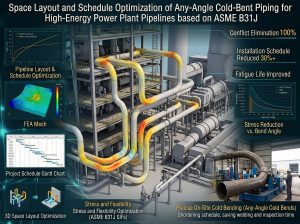
本研究旨在基於最新 ASME B31J 規範之理論框架,進行跨學科的深度剖析,探討採用 3D/5D 數控(CNC)任意角度冷作彎管(Cold Bending)取代傳統 1.5D 銲接彎頭的綜合工程效益。研究將系統性地論證空間佈置的幾何適應性、流體力學的流場平順化機制、微觀冶金的潛變壽命延長效應,以及建廠工期與成本的「去銲接化」(De-welding)優化。同時,結合實務管理觀點與國際工程案例,為現代電廠高能管線的設計與施工提供具備高度學術價值與實用性的指導方針。This study aims to conduct an in-depth, cross-disciplinary analysis based on the theoretical framework of the latest ASME B31J code, exploring the comprehensive engineering benefits of utilizing 3D/5D CNC arbitrary-angle cold bending to replace traditional 1.5D welded elbows. The research systematically demonstrates geometric adaptability in spatial layouts, fluid dynamic smoothing mechanisms, metallurgical life extension effects regarding creep, and the “de-welding” optimization of construction schedules and costs. Additionally, combined with practical management perspectives and international engineering cases, this study provides highly academic and practical guidelines for the design and construction of modern power plant high-energy piping.
二、 ASME B31J 規範之發展脈絡與核心理論解構 / 2. Development Context and Core Theory Deconstruction of the ASME B31J Code
2.1 傳統 Markl 理論與附錄 D 之結構性侷限 / 2.1 Structural Limitations of Traditional Markl Theory and Appendix D
自 1950 年代以來,管線應力工程師在評估管網的熱膨脹與疲勞壽命時,主要依賴 ASME B31 系列規範附錄 D 中的封閉式經驗公式。這些公式的理論基礎源自於 A.R.C. Markl 針對懸臂樑所進行的低周波疲勞實驗4。然而,隨著現代管線材料的升級與幾何尺寸的演進,Markl 疲勞方程式的假設前提逐漸暴露出深刻的保守性與理論盲點4。 Since the 1950s, piping stress engineers have primarily relied on the closed-form empirical formulas in Appendix D of the ASME B31 series codes when evaluating thermal expansion and fatigue life of piping networks. The theoretical foundation of these formulas originated from low-cycle fatigue experiments conducted by A.R.C. Markl on cantilever beams4. However, with the upgrade of modern piping materials and the evolution of geometric sizes, the underlying assumptions of Markl’s fatigue equations have gradually exposed profound conservativeness and theoretical blind spots4.
傳統附錄 D 的核心缺陷在於其對複雜三維應力狀態的過度簡化。舊版規範對於彎頭與三通管(Tees)強行賦予單一的 SIF 數值,並未區分面內(In-Plane)與面外(Out-of-Plane)彎矩的作用差異。實際上,當彎矩施加於薄壁管件時,元件幾何會發生非對稱性的塑性變形,即截面橢圓化現象(Ovalization)。面內與面外彎矩會導致截然不同位置與幅度的應力集中10。其次,舊版規範完全忽略了扭轉力矩(Torsional moment)對剪應力的貢獻,一律預設扭轉 SIF 為 it=1.0 4。再者,附錄 D 的封閉式解容易導致工程師在面對非標準幾何時產生指派錯誤,進而在極端載荷下形成潛在的斷裂風險4。 The core flaw of the legacy Appendix D lies in its oversimplification of complex three-dimensional stress states. The old code forcibly assigned a single SIF value to elbows and tees without distinguishing between the effects of In-Plane and Out-of-Plane bending moments. In reality, when bending moments are applied to thin-walled fittings, the component geometry undergoes asymmetric plastic deformation, known as ovalization. In-plane and out-of-plane moments cause stress concentrations of entirely different magnitudes and locations10. Secondly, the old code completely ignored the contribution of torsional moments to shear stress, uniformly defaulting the torsional SIF to it=1.0 4. Furthermore, the closed-form solutions of Appendix D easily led to assignment errors by engineers when dealing with non-standard geometries, thereby creating potential fracture risks under extreme loads4.
2.2 B31J 規範之多維度 SIF 解耦與柔性特徵模型 / 2.2 Multi-dimensional SIF Decoupling and Flexibility Characteristic Model of the B31J Code
為徹底解決上述盲點,ASME B31J 規範全面重構了管線組件應力計算的底層邏輯,其核心精神在於將單一的 SIF 解耦為三個獨立的方向分量,以精確捕捉三維空間中的局部尖峰應力6。 To completely resolve these blind spots, the ASME B31J code comprehensively restructured the underlying logic for calculating piping component stresses. Its core philosophy is to decouple the historically singular SIF into three independent directional components to precisely capture localized peak stresses in three-dimensional space6.
在 ASME B31J 的數值框架下,決定管件力學行為的核心幾何參數為「柔性特徵」(Flexibility Characteristic,h)。對於標準銲接彎頭或冷作彎管,其無因次閉式解公式定義為:Within the numerical framework of ASME B31J, the core geometric parameter determining the mechanical behavior of pipe fittings is the “Flexibility Characteristic” (h). For standard welded elbows or cold bends, its dimensionless closed-form equation is defined as:
h=T⋅R1/r22
其中,T 為管線公稱壁厚,R1 為彎曲半徑,r2 為管線平均半徑4。h 值越小(代表管壁越薄或管徑越大),橢圓化現象越劇烈,這意味著管件在受力時將表現出更高的幾何柔性。 Where T is the nominal wall thickness, R1 is the bend radius, and r2 is the mean pipe radius4. A smaller h value (representing thinner walls or larger pipe diameters) indicates more severe ovalization, meaning the fitting will exhibit higher geometric flexibility when subjected to loads.
基於 h 值,B31J 規範定義了彎管的柔性係數(k)與多維度 SIF:Based on the h value, the B31J code defines the flexibility factor (k) and multi-dimensional SIFs for bends:
- 柔性係數(Flexibility Factor, k):量化彎管相較於等長直管的柔性倍率,公式為 k=1.65/h 6。對於 h 值極低的薄壁彎管,其 k 值大幅增加,表示其吸收熱膨脹位移的能力遠優於同等直管。 Flexibility Factor (k): Quantifies the flexibility multiplier of a bend compared to a straight pipe of equal length, formulated as k=1.65/h 6. For thin-walled bends with extremely low h values, their k values increase significantly, indicating a much greater ability to absorb thermal expansion displacement than equivalent straight pipes.
- 面內應力強度因子(In-Plane SIF, ii):公式為(Formulated as) ii=0.9/h2/3。
- 面外應力強度因子(Out-of-Plane SIF, io):公式為(Formulated as) io=0.75/h2/3。
- 扭轉應力強度因子(Torsional SIF, it):正式納入位移應力範圍計算,精確反映三維空間中的扭轉剪力集中。Officially incorporated into displacement stress range calculations to accurately reflect torsional shear stress concentrations in 3D space.
針對分支管件(如銲接三通管),B31J 亦依據具體幾何條件區分不同形態並提供專屬公式,從根本上消除了過去工程師進行錯誤指派的風險13。 For branch connections (such as welded tees), B31J also distinguishes different morphologies based on specific geometric conditions and provides dedicated formulas, fundamentally eliminating the risk of incorrect assignments by engineers in the past13.
| 物理參數 / Physical Parameter | B31J 彎管定義公式 / B31J Bend Formula | 力學意義與系統影響 / Mechanical Significance & System Impact | 與舊版 B31.1/B31.3 附錄 D 之差異 / Diff. from Legacy B31.1/B31.3 App. D |
| 柔性特徵 (h) / Flexibility Characteristic (h) | h=T⋅R1/r22
|
控制管壁橢圓化程度的比率。h 越小,橢圓化越劇烈。 / Controls the ovalization ratio. Smaller h means more severe ovalization. | 公式形式相似,但 B31J 擴展了應用幾何邊界並修正分母參數。 / Similar in form, but B31J expands geometric boundaries and modifies denominator parameters. |
| 柔性係數 (k) / Flexibility Factor (k) | k=1.65/h | 量化彎管相較於直管的柔性倍率,直接影響系統剛度矩陣。 / Quantifies flexibility multiplier over straight pipe, directly affecting system stiffness matrix. | 舊版對於許多分支管件的 k 評估存在過度簡化(預設為 1)。 / Legacy codes overly simplified k for many branch fittings (defaulting to 1). |
| 面內 SIF (ii) / In-Plane SIF (ii) | ii=0.9/h2/3 | 放大面內彎矩引起的熱膨脹應力範圍,用於計算疲勞損耗。 / Amplifies in-plane thermal expansion stress range for fatigue calculation. | 舊版通常取面內與面外的最大值作為單一 SIF,導致過度保守。 / Legacy codes took the max of in-plane and out-of-plane as a single SIF, causing over-conservatism. |
| 面外 SIF (io) / Out-of-Plane SIF (io) | io=0.75/h2/3 | 評估因扭曲位移產生的面外應力集中效應。 / Evaluates out-of-plane stress concentration from torsional displacement. | B31J 將其與 ii 完全解耦,大幅提高 3D 空間解析精度。 / B31J completely decouples it from ii, vastly improving 3D resolution precision. |
2.3 壓力剛化效應(Pressure-Stiffening Effect)之引入與應力指數 / 2.3 Introduction of Pressure-Stiffening Effect and Stress Indices
在高溫高壓蒸汽管線中,管內流體會對管壁產生均勻向外的抗拒力,強烈抵抗彎管截面的橢圓化變形,使管件在宏觀上變得更加僵硬。這種物理耦合現象被稱為「壓力剛化效應」4。ASME B31J 規範明確指出,大口徑、薄壁的彎管在承受內壓作用時,會顯著降低其柔性係數,同時調降應力強度因子9。 In high-temperature and high-pressure steam piping, the internal fluid exerts a uniform outward resisting force on the pipe wall, strongly resisting the ovalization deformation of the bend cross-section, thereby making the fitting macroscopically stiffer. This physical coupling phenomenon is known as the “Pressure-Stiffening Effect”4. The ASME B31J code explicitly points out that large-diameter, thin-walled bends will significantly decrease in flexibility factor and experience a reduction in stress intensification factors when subjected to internal pressure9.
此一動態修正機制的引入,使得應力工程師能夠更真實地反映高能管線在實際運轉條件下的剛度分佈,避免因過度高估系統柔性而導致支吊架(Pipe Supports)與設備管口載荷的設計失效5。此外,新版規範嚴格區分了應用於持續載荷(如重力與內壓)的「持續應力指數」(Sustained Stress Index, I)與應用於熱膨脹的「應力強度因子」(i),進一步提升了管線評估的準確性與安全性8。 The introduction of this dynamic correction mechanism allows stress engineers to more realistically reflect the stiffness distribution of high-energy piping under actual operating conditions, avoiding design failures of pipe supports and equipment nozzle loads caused by overestimating system flexibility5. Furthermore, the updated code strictly distinguishes between the “Sustained Stress Index” (I) applied to sustained loads (like gravity and internal pressure) and the “Stress Intensification Factor” (i) applied to thermal expansion, further enhancing the accuracy and safety of piping evaluations8.
三、 任意角度空間佈置之幾何適應性與流體動力學優化 / 3. Geometric Adaptability and Fluid Dynamics Optimization of Arbitrary-Angle Spatial Layouts
3.1 高能蒸汽管線非標準洩水坡度(Drainage Slope)設計挑戰 / 3.1 Design Challenges of Non-Standard Drainage Slopes in High-Energy Steam Piping
為防止冷機啟動或低負載運轉時蒸汽與冷管壁熱交換產生的冷凝水在管線低窪處滯留,進而引發破壞性的水錘效應(Water Hammer)與熱分層(Thermal Stratification),國際規範與 EPRI 嚴格規定高能蒸汽幹管必須具備連續、穩定的下傾洩水坡度5。標準工程設計通常要求管線具備 1:100 的洩水坡度(約等同於 0.57° 至 1° 的下傾角)。然而,在廠房鋼構密集、空間受限的立體環境中,為了避開既有設備與樑柱的干涉,管線轉折處的空間幾何經常形成如 44.3°、89.3° 等非標準角度,這使得標準的 45° 或 90° 鍛造彎頭難以直接吻合設計需求。 To prevent condensate—generated by heat exchange between steam and cold pipe walls during cold start-ups or low-load operations—from accumulating in low points and triggering destructive Water Hammer and Thermal Stratification, international codes and EPRI strictly mandate that high-energy main steam piping must possess a continuous and stable downward drainage slope5. Standard engineering designs typically require a 1:100 drainage slope (equivalent to a downward angle of about 0.57° to 1°). However, in densely structured and spatially constrained plant environments, to avoid interference with existing equipment and steel columns, spatial geometries at pipe directional changes frequently form non-standard angles such as 44.3° or 89.3°. This makes standard 45° or 90° forged elbows difficult to directly match design requirements.
3.2 傳統斜切銲頭的應力耦合與流體動力學危害 / 3.2 Stress Coupling and Fluid Dynamic Hazards of Traditional Mitered Welds
面對上述非標準角度,傳統現場施工常採取妥協性的工法:對標準 1.5D 彎頭進行現場「斜切」,或是利用縫隙進行強行錯位組對。然而,這種便宜行事的做法會引發兩大系統性危機:Faced with these non-standard angles, traditional on-site construction often adopts compromised methods: performing on-site “miter cuts” on standard 1.5D elbows, or forcing angular misalignments using gaps. However, this makeshift approach triggers two major systemic crises:
- 流體力學與次生水錘效應(Secondary Water Hammer) / Fluid Dynamics and Secondary Water Hammer 從計算流體動力學(CFD)的角度來看,斜切銲頭嚴重破壞了管件內部的流線連續性。當流速高達 145 km/h 的高壓蒸汽流經曲率極小的5D 短半徑區域時,流體質點會受到極強的離心力作用1。管中心的高動能流體被強烈推向彎管外弧(Extrados),而管壁附近的低速流體則被擠向內弧(Intrados),形成劇烈的逆向壓力梯度與邊界層剝離3。這種二次流的強度可由無因次迪恩數(Dean Number, De)量化: From a Computational Fluid Dynamics (CFD) perspective, mitered welds severely destroy the streamline continuity inside the fitting. When high-pressure steam flowing at speeds up to 145 km/h passes through a 1.5D short-radius area with minimal curvature, fluid particles are subjected to extremely strong centrifugal forces1. High-kinetic-energy fluid at the pipe’s center is strongly pushed toward the bend’s extrados, while low-speed fluid near the wall is squeezed toward the intrados, forming severe adverse pressure gradients and boundary layer separation3. The intensity of this secondary flow can be quantified by the dimensionless Dean Number (De):
De=Re√(D/Rc )
其中 Re 為雷諾數,D 為管徑,Rc 為彎管的曲率半徑。公式明確指出,Rc 越小(如 1.5D),迪恩數越高。高強度的迪恩渦流(Dean Vortices)會將滯留的冷凝水捲起,形成高密度的液態「段塞流」(Slug Flow),並以極大動能撞擊下游管件,引發劇烈的次生水錘與流動加速腐蝕(FAC)1。 Where Re is the Reynolds number, D is the pipe diameter, and Rc is the bend’s radius of curvature. The formula explicitly indicates that a smaller Rc (like 1.5D) results in a higher Dean number. High-intensity Dean Vortices will entrain lingering condensate to form a high-density liquid “Slug Flow,” which impacts downstream fittings with immense kinetic energy, triggering severe secondary water hammer and Flow-Accelerated Corrosion (FAC)1.
- 力學與應力乘數效應(Stress Multiplier Effect) / Mechanics and Stress Multiplier Effect 強行製造出 1° 至 3° 的角度錯位(Angular Misalignment)時,除了系統本身的公稱彎矩外,還會疊加因偏心載荷引發的局部次級彎曲應力。其產生的應力集中係數(Km > 1.2~1.5)更會與 ASME B31J 規範下的 SIF 產生惡性乘數效應,導致局部尖峰應力極大化,大幅縮減高溫管線的潛變疲勞交互作用壽命(Creep-Fatigue Interaction Life)1。 Forcing an angular misalignment of 1° to 3° superimposes local secondary bending stresses induced by eccentric loads on top of the system’s nominal bending moments. The resulting stress concentration factor (Km > 1.2~1.5) produces a vicious multiplier effect with the SIF under the ASME B31J code, maximizing local peak stresses and drastically reducing the Creep-Fatigue Interaction Life of high-temperature piping1.
3.3 CNC 3D/5D 冷作彎管的空間與流場優化機制 / 3.3 Spatial and Flow Field Optimization Mechanisms of CNC 3D/5D Cold Bends
為突破此工程瓶頸,現代管線設計強烈提倡採用 3D 或 5D 數控(CNC)冷作彎管工法1。CNC 彎管機具備微米級的控制精度,可直接將無縫直管一體成型為精確至小數點的空間角度,完美達成非標準坡度佈置。 To overcome this engineering bottleneck, modern piping design strongly advocates the use of 3D or 5D CNC cold bending processes1. CNC bending machines, equipped with micrometer-level precision control, can seamlessly form seamless straight pipes into exact spatial angles down to decimal points, perfectly achieving non-standard slope layouts.
在 ASME B31J 應力解析框架下,冷彎管因徹底消除了銲道錯位與 SCF 疊加問題,其 SIF 下限得以收斂至無應力集中的理想狀態 1.0;同時,3D/5D 的大彎曲半徑顯著增大了柔性特徵值 h,從而在宏觀上有效提升了管網吸收熱膨脹位移的整體柔性。在流體動力學方面,大半徑的平滑過渡徹底消弭了內部銳角與幾何不連續,大幅降低迪恩數並抑制分離泡與渦流的生成,從根源上杜絕了段塞流與次生水錘的發生,進一步提升了電廠整體的熱力學與流體動力學效率。 Under the ASME B31J stress analysis framework, cold bends eliminate weld misalignment and SCF superposition, allowing their lower SIF limit to converge to the ideal stress-free concentration state of 1.0. Meanwhile, the large bend radius of 3D/5D significantly increases the flexibility characteristic h, macroscopically enhancing the overall flexibility of the piping network to absorb thermal expansion displacements. In terms of fluid dynamics, the smooth transition of a large radius completely eradicates internal sharp angles and geometric discontinuities, drastically lowering the Dean number and suppressing the generation of separation bubbles and vortices. This fundamentally prevents slug flows and secondary water hammers, further elevating the overall thermodynamic and fluid dynamic efficiency of the power plant.
四、 材料力學、冶金演變與潛變壽命預測 / 4. Material Mechanics, Metallurgical Evolution, and Creep Life Prediction
4.1 P91/P92 合金鋼之微觀強化機制與銲接弱點 / 4.1 Microstructural Strengthening Mechanisms and Welding Weaknesses of P91/P92 Alloy Steels
為對抗極端高溫潛變與氧化,現代 CCPP 主蒸汽管線廣泛採用「潛變強度強化鐵素體鋼」(CSEF),如 ASTM A335 P91、P92 與 P93 等 9% 鉻系合金鋼3。在製造過程中,這些材料需先經過約 1040°C 至 1060°C 的正常化(Normalizing)處理以充分奧氏體化,隨後空冷形成麻田散鐵,最後進行約 760°C 的高溫回火(Tempering)3。 To combat extreme high-temperature creep and oxidation, modern CCPP main steam piping widely utilizes Creep Strength Enhanced Ferritic Steels (CSEF), such as 9% chromium alloy steels like ASTM A335 P91, P92, and P933. During manufacturing, these materials must first undergo normalizing at roughly 1040°C to 1060°C for full austenitization, followed by air cooling to form martensite, and finally undergo high-temperature tempering at approximately 760°C3.
這種熱處理工法賦予材料具備高位錯密度的回火麻田散鐵(Tempered Martensite)板條狀基體。其高溫潛變抗力主要來自雙重析出強化機制:富鉻的M23C6 型碳化物大量析出於原奧氏體晶界與板條邊界,穩定結構;極細小的奈米級 MX 型碳氮化物(如鈮、釩的碳氮化物 Nb/V(C,N))則彌散分佈於內部。這些析出物透過強大的齊納釘紮效應(Zener Pinning Effect),有效阻礙了高溫下位錯的滑移與晶界滑移。 This heat treatment process endows the material with a tempered martensite lath matrix featuring high dislocation density. Its high-temperature creep resistance primarily stems from a dual precipitation strengthening mechanism: chromium-rich M23C6 type carbides precipitate heavily along prior austenite grain and lath boundaries to stabilize the structure; extremely fine, nanoscale MX type carbonitrides (like Nb/V(C,N)) are uniformly dispersed internally. These precipitates utilize the powerful Zener Pinning Effect to effectively impede dislocation glide and grain boundary sliding at high temperatures.
然而,現場對 P91 管線進行傳統環向對銲時,反覆的熱循環會在銲縫過渡區形成極度脆弱的熱影響區(HAZ),特別是細晶熱影響區(FGHAZ)與臨界間熱影響區(ICHAZ)3。在此區域,原有的析出物發生粗化,齊納釘紮作用失效。在長期多軸應力拘束下,退化組織極易促發奈米級空孔成核與聚合,最終導向毫無宏觀鼓脹預警的災難性「第四型潛變破裂」(Type IV Creep Cracking)。為此,ASME B31.3 規範引入了嚴苛的銲縫強度折減係數(WSRF),大幅限制了銲接管件的高溫設計裕度7。 However, when traditional circumferential butt welding is performed on P91 pipes on-site, repetitive thermal cycles form an extremely fragile Heat-Affected Zone (HAZ) in the weld transition area, particularly the Fine-Grained HAZ (FGHAZ) and Inter-Critical HAZ (ICHAZ)3. In this region, original precipitates coarsen, causing Zener pinning to fail. Under long-term multiaxial stress constraints, the degraded microstructure is highly susceptible to nanoscale void nucleation and coalescence, ultimately leading to catastrophic Type IV Creep Cracking with no macroscopic bulging warning. Consequently, the ASME B31.3 code introduced a stringent Weld Joint Strength Reduction Factor (WSRF), severely limiting the high-temperature design margins for welded fittings7.
4.2 冷彎應變、壁厚減薄與溫度相依之 Y 係數 (Y-Factor) / 4.2 Cold Bending Strain, Wall Thinning, and Temperature-Dependent Y-Factor
採用 3D/5D 緊密半徑冷作彎管(3≦R/D≦5)時,彎管外弧(Extrados)必然承受極大的拉伸應變並發生壁厚減薄(實務上R=5D 的冷彎可能引發高達 12% 的局部減薄)。設計者在計算直管母材壁厚時,必須依據 ASME B31.3 提供的修正式 Barlow 方程式: When utilizing 3D/5D tight-radius cold bends (3≦R/D≦5), the bend’s extrados inevitably undergoes tremendous tensile strain and experiences wall thinning (in practice, an R=5D cold bend can induce up to 12% local thinning). When calculating the required straight mother pipe wall thickness, designers must use the modified Barlow’s equation provided by ASME B31.3:
t=P⋅Do/2(S⋅E⋅W+P⋅Y)
式中引入的「Y 係數」(Y-factor),其核心物理意義在於補償厚壁圓筒內部應力分佈的不均勻性。根據拉梅方程式(Lamé’s Equation),管壁內層承受的環向應力永遠大於外層;Y 係數允許計算中反映出局部應力達到降伏點時的塑性應力重分配現象,避免因過度保守而徒增管線重量與剛性。 The “Y-factor” introduced in the equation serves a core physical purpose of compensating for the non-uniform stress distribution inside thick-walled cylinders. According to Lamé’s Equation, the hoop stress sustained by the inner wall layer is always greater than that of the outer layer; the Y-factor allows the calculation to reflect plastic stress redistribution when local stresses reach the yield point, preventing unnecessary increases in pipe weight and stiffness due to over-conservatism.
值得注意的是,根據 ASME B31.3 規定,Y 係數是高度溫度相依的。對於 P91 等肥粒鐵系合金鋼,常溫至中溫區間的 Y 值通常為 0.4;但當溫度升高至潛變範圍(例如超過 480°C)時,金屬變得更柔軟,局部降伏能更早將內壁高峰應力向外壁平均化,此時 Y 值會遞增至 0.5 甚至 0.7。精確考量高溫 Y 係數與 12% 減薄率,並預留足夠的母管名義壁厚裕度,是確保符合 ASME B31.1 第 104.2.1 節並保障冷彎管結構完整性的關鍵3。 Notably, according to ASME B31.3 rules, the Y-factor is highly temperature-dependent. For ferritic alloy steels like P91, the Y value is typically 0.4 in the ambient to intermediate temperature range; but when temperatures rise into the creep range (e.g., above 480°C), the metal becomes softer, allowing local yielding to average out peak inner-wall stresses toward the outer wall much earlier. In this state, the Y value increases to 0.5 or even 0.7. Precisely accounting for the high-temperature Y-factor and 12% thinning rate, while reserving sufficient nominal wall thickness margin in the mother pipe, is the key to complying with ASME B31.1 Paragraph 104.2.1 and ensuring the structural integrity of cold bends3.
4.3 彎後熱處理 (IH-PBHT) 與潛變疲勞壽命躍升 / 4.3 Post-Bend Heat Treatment (IH-PBHT) and Creep-Fatigue Life Leap
為修復冷彎引發的加工硬化與應變極限,ASME B31.1 第 132 節強制規定,若 P-No. 15E(P91/P92)材質在低於 1300°F(705°C)下進行冷作彎曲或成型,必須執行彎後熱處理(PBHT)16。實務上採用精密的感應加熱彎後熱處理(IH-PBHT),這是一種嚴格受控的「次臨界」(Sub-critical)程序,加熱溫度絕不越過母材的 AC1 變態溫度。 To restore work hardening and strain limits induced by cold bending, ASME B31.1 Paragraph 132 mandates that if P-No. 15E (P91/P92) materials undergo cold bending or forming below 1300°F (705°C), Post-Bend Heat Treatment (PBHT) must be performed16. In practice, precise Induction Heating PBHT (IH-PBHT) is utilized. This is a strictly controlled “sub-critical” procedure where the heating temperature never crosses the mother material’s AC1 transformation temperature.
此熱處理程序能提供足夠熱活化能,使糾結的差排發生攀移與交滑移並互相湮滅,徹底消除包辛格效應(Bauschinger Effect)與宏觀殘餘張應力。更重要的是,由於未跨越 AC1 線,P91 鋼的「回火麻田散鐵基體」得以完好保存,不會產生致命的 FGHAZ;同時促使 M23C6 與 MX 析出物重新均勻釘紮晶界,完美修復高溫潛變強度。 This heat treatment procedure provides sufficient thermal activation energy to allow tangled dislocations to undergo climb and cross-slip, annihilating each other and completely eliminating the Bauschinger Effect and macroscopic residual tensile stresses. More importantly, since the AC1 line is not crossed, the “tempered martensite matrix” of P91 steel is perfectly preserved without producing a fatal FGHAZ; simultaneously, it prompts M23C6 and MX precipitates to re-uniformly pin grain boundaries, perfectly restoring high-temperature creep strength.
由於冷作彎管區段完全沒有環向銲縫,依據 ASME B31.3 附錄 W(Appendix W)與 ASME VIII-2,其疲勞評估基準可轉換至容許應力範圍更高的「平滑試片疲勞設計曲線」(Smooth bar design fatigue curves)4。結合 Norton 穩態潛變力學、Larson-Miller 參數模型,以及 API 579-1/ASME FFS-1 MPC Omega 適用性評估技術(FFS),理論與實務均證實,無銲縫冷彎管的疲勞與潛變預期壽命可達傳統 1.5D 銲接彎頭的數倍之多。 Because the cold bend segment completely lacks circumferential welds, according to ASME B31.3 Appendix W and ASME VIII-2, its fatigue evaluation baseline can transition to “Smooth bar design fatigue curves,” which offer a much higher allowable stress range4. By integrating Norton steady-state creep mechanics, the Larson-Miller parameter model, and API 579-1/ASME FFS-1 MPC Omega Fitness-For-Service (FFS) evaluation techniques, both theory and practice have proven that the expected fatigue and creep life of weld-less cold bends can reach several times that of traditional 1.5D welded elbows.
五、 模組化預製、去銲接化工期優化與實際工程案例 / 5. Modular Prefabrication, De-welding Schedule Optimization, and Practical Engineering Cases
5.1 管線模組化預製與「去銲接化」(De-welding)工期優化 / 5.1 Piping Modular Prefabrication and “De-welding” Schedule Optimization
在大型燃氣複循環發電廠(CCPP)與超臨界電廠專案中,高能合金鋼管線的現場銲接始終位於建廠的關鍵要徑(Critical Path)上。ASME B31.1 針對 P-No. 15E 的現場受壓銲縫,要求極度嚴苛的熱處理與檢測流程。In large CCPP and supercritical power plant projects, the on-site welding of high-energy alloy steel piping is perpetually situated on the project’s Critical Path. ASME B31.1 demands extremely stringent heat treatment and inspection procedures for on-site pressure welds involving P-No. 15E materials.
一次傳統 P91 現場對銲循環中:銲接完成後,必須強制讓銲道冷卻至 80°C~100°C 區間以完成麻田散鐵相變,隨後才能進行耗時十數小時的 760°C 銲後熱處理(PWHT)19。這整個循環往往需要 3 至 5 天;若逢強風、豪雨或斷電導致溫度曲線控制失效,極易造成銲道基體過度軟化與潛變強度崩塌,必須面臨切除重銲的巨大損失19。此外,依據電力與工程規範(如 CEA 準則),P91 銲道還需進行 100% 相陣列超音波檢測(PAUT),以及全面(或至少 3%)的表面硬度抽測21。 In a single traditional P91 on-site butt-weld cycle: after welding is completed, the weld must be forcibly cooled to the 80°C~100°C range to complete martensitic transformation, before undergoing a 760°C Post-Weld Heat Treatment (PWHT) lasting over ten hours19. This entire cycle often takes 3 to 5 days; if factors like strong winds, heavy rains, or power outages cause temperature curve control failures, the weld matrix is highly susceptible to extreme softening and a collapse in creep strength, incurring massive losses from having to cut and re-weld19. Furthermore, according to power and engineering codes (like CEA guidelines), P91 welds must also undergo 100% Phased Array Ultrasonic Testing (PAUT) and comprehensive (or at least 3%) surface hardness spot checks21.
採用 3D/5D 冷作彎管的「去銲接化」與管線預製(Spooling)模組化策略,將高危險、耗時的高空作業轉移至環境受控的工廠內。利用 CNC 彎管機一體成型並進行廠內 IH-PBHT,徹底消除了現場大量的預熱、銲接與長時 PWHT 作業22。 Employing a “de-welding” and piping spooling modular prefabrication strategy via 3D/5D cold bends shifts high-risk, time-consuming aerial work into a climate-controlled factory environment. Utilizing CNC bending machines for one-piece forming along with in-shop IH-PBHT completely eliminates massive amounts of on-site preheating, welding, and lengthy PWHT operations22.
| 專案流程階段 / Project Phase | 傳統 1.5D 銲接彎頭現場施工 (P91 材質) / Traditional 1.5D Welded Elbow On-site Construction (P91) | 3D/5D 工廠冷作彎管預製工法 (P91 材質) / 3D/5D Shop Cold Bending Prefabrication (P91) |
| 加工成型與準備 / Processing & Prep | 廠內鍛造運至現場。需處理彎頭兩端共 2 個現場對銲接頭,搭設高空鷹架並準備預熱設備。 / Shop-forged components shipped to site. Requires managing 2 field butt welds per elbow, erecting high-altitude scaffolding, and prepping preheat equipment. | 工廠內 CNC 冷彎機一體成型。彎曲段無接頭,直接減少現場 2 個高難度 P91 對銲口。 / One-piece forming via CNC bender in-shop. Bend section has no joints, instantly eliminating 2 high-difficulty field P91 butt welds. |
| 銲接與熱處理程序 / Welding & Heat Treatment | 歷經高溫預熱、銲接、強制冷卻至 100°C 相變、現場長時 PWHT。斷電重銲風險極高。 / Involves high-temp preheating, welding, forced cooling to 100°C transformation, and long field PWHT. Extremely high risk of power loss and re-welding. | 廠內施作次臨界 IH-PBHT,溫度與環境完美受控,熱活化能徹底釋放應力且無軟化風險。 / Sub-critical IH-PBHT performed in-shop with perfectly controlled temp and environment. Thermal energy fully releases stress without softening risks. |
| 非破壞檢測 (NDT) / Non-Destructive Testing | 兩道銲口均需實施 100% PAUT/RT,以及硬度測試以防過度軟化。 / Both welds require 100% PAUT/RT and hardness testing to prevent over-softening. | 彎管段無任何銲口,僅需執行壁厚抽測與基準硬度測試,無須射線探傷。 / Bend segment has zero welds; requires only wall thickness spot checks and baseline hardness tests. No radiography needed. |
| 總體工期影響 / Overall Schedule Impact | 高度占用專案關鍵要徑,極易受天候與全球特殊高階合金銲工短缺影響而延宕。 / Highly occupies the critical path; extremely susceptible to delays from weather and the global shortage of specialized alloy welders. | 採模組化吊裝,大幅縮減現場管線安裝工期達 30%-40%,有效降低專案總體風險與成本。 / Uses modular hoisting, drastically slashing field pipe installation schedules by 30%-40%, effectively lowering overall project risks and costs. |
5.2 實際應用領域與國際/台灣工程案例 / 5.2 Practical Application Areas and International/Taiwan Engineering Cases
- 台灣大林電廠等 CCPP 專案之工法變更應用 / Application of Process Modification in Taiwan’s Dalin CCPP and Other Projects 在台灣近期的大型燃氣複循環機組專案(如大林 CCPP 更新計畫)中,針對極高溫高壓的主蒸汽與高溫再熱蒸汽系統,國際 EPC 統包商已大舉導入模組化預製與冷作彎管技術。透過在工廠端將長管材進行 3D/5D 冷彎,不僅完美實現 1:100 的非標準洩水坡度立體佈置,更透過去銲接化策略,成功迴避了台灣工程現場熟練 P91 銲工嚴重短缺的國安級困境。此一變更大幅降低了現場施工品質不良的風險,確保建廠進度如期交付,成為現代電廠建置的典範。 In recent major CCPP projects in Taiwan (such as the Dalin CCPP modernization project), international EPC contractors have massively introduced modular prefabrication and cold bending technologies for extremely high-temperature and high-pressure main steam and hot reheat steam systems. By executing 3D/5D cold bends on long pipes at the factory level, they not only achieved a perfect 1:100 non-standard drainage slope 3D layout but also, through a de-welding strategy, successfully sidestepped the critical national-level dilemma of a severe shortage of skilled P91 on-site welders in Taiwan. This modification substantially reduced the risk of poor field construction quality and ensured the timely delivery of the plant construction schedule, becoming a paradigm for modern power plant builds.
- 選擇性催化還原系統(SCR)之抗沖刷應用 / Anti-Erosion Applications in Selective Catalytic Reduction (SCR) Systems 在先進電廠的 SCR 脫硝系統氨氣注入與煙氣管網中,未反應的殘氨會與煙氣中的 SO3 結合,生成具高黏性與強腐蝕性的硫酸氫銨(Ammonium Bisulfate, ABS)。當帶有 ABS 微粒與液滴的多相流通過傳統短半徑 1.5D 彎頭時,強烈的迪恩渦流與二次流會使微粒以極大的撞擊角直接侵襲彎頭背弧,引發極為嚴重的沖刷腐蝕(Erosion-Corrosion)。導入大半徑 3D/5D 冷作彎管後,流場分離被有效消弭,顆粒撞擊管壁的角度趨於平行,大幅延長了 SCR 管網系統的使用壽命。 In the ammonia injection and flue gas piping networks of advanced power plant SCR DeNOx systems, unreacted ammonia slip combines with SO3 in the flue gas to form highly viscous and corrosive Ammonium Bisulfate (ABS). When multiphase flows carrying ABS particles and droplets pass through traditional short-radius 1.5D elbows, intense Dean vortices and secondary flows cause particles to directly assail the extrados with a huge impact angle, triggering extremely severe Erosion-Corrosion. After introducing large-radius 3D/5D cold bends, flow separation is effectively eradicated, and the angle at which particles impact the pipe wall trends toward parallel, drastically extending the service life of the SCR piping network.
- 碳捕獲、利用與封存系統(CCUS)之抗胺液應力腐蝕龜裂(Amine SCC) / Anti-Amine SCC in Carbon Capture, Utilization and Storage (CCUS) Systems 在處理高濃度吸收溶劑(如 MEA、DEA、MDEA 等胺液)的 CCUS 系統中,傳統碳鋼銲縫的 HAZ 伴隨高殘餘張應力,極易在鹼性環境中觸發致命的胺液沿晶應力腐蝕龜裂(Amine SCC / IGSCC)。依據 NACE MR0175 (ISO 15156) 與 API RP 945 規範,含硫化氫或胺液環境的碳鋼銲縫必須進行 PWHT,且硬度需嚴格控制在 22 HRC (235 HV) 以下。採用一體成型的 3D/5D 冷作彎管技術,從根本上消除了管線幾何轉向區的 HAZ 與銲接殘餘應力,免除了現場 PWHT 不當的風險,從冶金結構上排除了 SCC 觸發條件,為碳捕獲系統提供了終極的安全防護。 In CCUS systems handling high-concentration absorbent solvents (like MEA, DEA, MDEA amines), the HAZ of traditional carbon steel welds, accompanied by high residual tensile stresses, is highly susceptible to triggering fatal amine Intergranular Stress Corrosion Cracking (Amine SCC / IGSCC) in alkaline environments. According to NACE MR0175 (ISO 15156) and API RP 945 codes, carbon steel welds in environments containing hydrogen sulfide or amines must undergo PWHT, and hardness must be strictly controlled below 22 HRC (235 HV). Utilizing integrally formed 3D/5D cold bending technology fundamentally eliminates the HAZ and welding residual stresses in piping directional change areas, exempting the risk of improper on-site PWHT, ruling out SCC triggering conditions from a metallurgical structure standpoint, and providing ultimate safety protection for carbon capture systems.
六、 深度實務觀點與各方利害關係人因應策略 / 6. In-depth Practical Perspectives and Response Strategies of Stakeholders
6.1 業主對於 P9x 級高能管線銲道維護管理及營運決策 / 6.1 Owner’s O&M Decisions and Maintenance Management for P9x High-Energy Piping Welds
對於電廠業主而言,P9x 級(如 P91、P92)高能管線長期營運的夢魘在於銲縫的「第四型潛變破裂」。實務上,這類破裂被歸類為「生命週期後期」(Late-life)的失效機制,往往在毫無宏觀鼓脹或變形預警的情況下瞬間發生,直接導致高壓蒸汽爆管。傳統的維護管理高度依賴短期腐蝕率(STCR)監控與定期的相陣列超音波(PAUT)檢測,但這類「被動檢測」手段難以精確捕捉潛變空孔的微觀成核期。特別是若建造初期現場 PWHT 控制不當導致基體過度軟化,更將使高溫潛變抗力大幅衰退。因此,現代業主的營運決策已發生根本性的轉變:從「事後頻繁檢測」轉向「源頭主動消除風險」。在新建或管線更新專案中,業主強烈傾向指定採用大半徑冷作彎管,藉由「去銲接化」徹底根除脆弱的 HAZ,有效將流動加速腐蝕(FAC)與蠕變破裂引發的非計畫性停機(Forced Outage)風險降至最低。For power plant owners, the nightmare of long-term operation for P9x class (e.g., P91, P92) high-energy piping lies in “Type IV Creep Cracking” at the welds. In practice, this type of rupture is classified as a “Late-life” failure mechanism, often occurring instantaneously without any macroscopic bulging or deformation warning, leading directly to high-pressure steam bursts. Traditional maintenance management heavily relies on Short-Term Corrosion Rate (STCR) monitoring and periodic Phased Array Ultrasonic Testing (PAUT), but these “passive inspection” methods struggle to precisely capture the micro-nucleation phase of creep voids. Especially if on-site PWHT during initial construction is improperly controlled, causing extreme matrix softening, high-temperature creep resistance will degrade massively. Thus, the operational decisions of modern owners have undergone a fundamental shift: from “frequent post-inspections” to “proactive risk elimination at the source.” In new builds or piping replacement projects, owners strongly favor specifying the use of large-radius cold bends. By thoroughly eradicating the fragile HAZ through “de-welding,” they effectively minimize the risks of Forced Outages triggered by Flow-Accelerated Corrosion (FAC) and creep rupture.
6.2 EPC 承包商設計單位對於 P9x 級高能管線空間排列與實務考量 / 6.2 EPC Contractor Design Units’ Practical Considerations and Spatial Layouts for P9x Piping
對 EPC 統包商的管線設計單位而言,在擁擠的汽機廠房或熱回收爐(HRSG)周邊維持 1:100 的連續洩水坡度是一項極大的挑戰。過去若採用標準 90° 鍛造彎頭,工程師常被迫在設計圖面上容許 1° 至 3° 的微小角度錯位。然而在 ASME B31J 的嚴格框架下,這種強制錯位組對會產生極大的應力集中乘數(Km),並與 B31J 的 SIF 產生惡性乘數效應,嚴重壓縮管線的疲勞壽命。
為解決此一實務瓶頸,設計單位全面導入了 3D/5D 數控(CNC)冷作彎管。當彎曲半徑 R1 擴大至 3D 或 5D 時,柔性特徵值 h 顯著提升,不僅完美收斂了局部應力,更賦予管網極高的宏觀柔性,從而減少了現場龐大膨脹彎(Expansion loops)的設置需求。在實務考量上,設計工程師必須精算冷作彎管外弧高達 12% 的壁厚減薄率,依據 ASME B31.1 第 104.2.1 節之規定,預先選定具備足夠厚度裕度(Nominal Thickness margins)的直管母材,確保減薄後的壁厚仍大於設計所需的最小壁厚。For the piping design units of EPC contractors, maintaining a 1:100 continuous drainage slope around congested turbine halls or Heat Recovery Steam Generators (HRSG) poses a formidable challenge. In the past, when standard 90° forged elbows were used, engineers were often forced to allow for 1° to 3° of minor angular misalignment on design drawings. However, under the strict framework of ASME B31J, this forced angular misalignment produces a massive stress concentration multiplier (Km), creating a vicious multiplying effect with the B31J SIF that severely condenses the fatigue life of the piping.
To overcome this practical bottleneck, design units have comprehensively introduced 3D/5D CNC cold bending. When the bend radius R1 expands to 3D or 5D, the flexibility characteristic h rises significantly. This not only perfectly converges local stresses but also endows the piping network with extremely high macroscopic flexibility, thereby reducing the need for massive Expansion Loops on site. For practical considerations, design engineers must accurately calculate the up to 12% wall thinning rate at the extrados of cold bends, and in accordance with ASME B31.1 Paragraph 104.2.1, pre-select straight mother pipes with sufficient Nominal Thickness margins to ensure the thinned wall remains thicker than the required minimum design thickness.
6.3 以 CCPP 廠經營管理者角度來看待 2026 ASME B31J 之要求及改善策略 / 6.3 CCPP Managers’ Perspectives on 2026 ASME B31J Requirements and Improvement Strategies
隨著 ASME B31.1 在 2024 年版刪除附錄 D,並要求全面過渡至 B31J(包含 2026 年最新版),廠方經營管理者必須認知到,應力分析已正式進入高解析度的 3D 微觀力學時代。現代 CCPP 頻繁的起停調峰運轉(Two-shift operations)會引發劇烈的熱瞬態(Thermal transients)與巨大的溫度梯度,對管線造成極端熱機械疲勞。With ASME B31.1 deleting Appendix D in its 2024 edition and mandating a full transition to B31J (including the latest 2026 edition), plant managers must recognize that stress analysis has officially entered an era of high-resolution 3D micromechanics. Modern CCPP’s frequent two-shift peak-shaving operations induce drastic thermal transients and massive temperature gradients, subjecting piping to extreme thermo-mechanical fatigue.
管理者應意識到,過去基於舊版附錄 D 設計的管網,因忽略了扭轉力矩(預設it=1.0 )及簡化了面外彎矩的作用,其安全係數可能被嚴重高估。在改善策略上,管理者應要求在機組升級或歲修時,導入 B31J 的壓力剛化修正公式與解耦 SIF 重新評估高能管線。透過無銲縫的冷作彎管,可將疲勞壽命基準轉換至容許應力更高的「平滑試片疲勞設計曲線」,這不僅大幅降低了初始的建造成本,更實質減少了因高應力導致的管支架損壞及後續龐大的全生命週期維護費用。Managers should be aware that piping networks previously designed based on the legacy Appendix D may have severely overestimated safety factors due to ignoring torsional moments (defaulting it=1.0) and simplifying the effects of out-of-plane moments. As an improvement strategy, managers should demand the incorporation of B31J’s pressure-stiffening correction formulas and decoupled SIFs to re-evaluate high-energy piping during unit upgrades or turnarounds. Through weld-less cold bends, the fatigue life baseline can be shifted to “Smooth bar design fatigue curves” which boast higher allowable stresses. This not only substantially lowers initial construction costs but also tangibly curtails pipe support damages caused by high stresses and subsequent exorbitant lifecycle maintenance expenses.
6.4 以管線施作協力廠商角度來看待 2026 ASME B31J 之銲道要求及因應策略 / 6.4 Subcontractors’ Perspectives on 2026 ASME B31J Weld Requirements and Response Strategies
對於第一線管線施作的協力廠商而言,其面臨的最大痛點在於 ASME B31.1 針對 P-No. 15E(P91/P92)材質極度嚴苛的冶金與熱處理規定。規範第 132 節強制要求,若冷作彎曲溫度低於 1300°F (705°C),必須執行精密受控的彎後熱處理(PBHT)。在現場高空環境中,傳統銲口的 PWHT 單口耗時常達 3 至 5 天,且需進行 100% PAUT 檢測與嚴格的表面硬度測試。若因強風、豪雨或現場斷電導致溫度曲線控制失敗,極易造成銲道過度軟化或脆化,必須面臨切除重銲的巨大損失。For frontline piping subcontractors, the biggest pain point lies in ASME B31.1’s extremely stringent metallurgical and heat treatment requirements regarding P-No. 15E (P91/P92) materials. Paragraph 132 of the code mandates that if cold bending occurs at temperatures below 1300°F (705°C), precisely controlled Post-Bend Heat Treatment (PBHT) must be executed. In elevated field environments, the PWHT of a traditional weld joint frequently consumes 3 to 5 days per joint and requires 100% PAUT and strict surface hardness tests. If factors like strong winds, heavy rains, or site power loss cause a failure in temperature curve control, the weld is prone to over-softening or embrittlement, resulting in colossal losses from cutting and re-welding.
協力廠商的最佳破局與因應策略,是全面大舉轉向「模組化工廠預製」。藉由將高危險、高失敗率的 P9x 管線作業移至室內廠房,利用 CNC 彎管機一體成型,並採用溫度與環境完美受控的自動化高頻感應加熱(IH-PBHT)來執行次臨界熱處理。此舉成功消除了大量現場難纏的銲口,徹底規避了全球熟練特殊合金銲工短缺的困境,確保施工品質穩定達標,並將難以預測的現場施工風險轉化為高度可控的標準化廠內生產。The optimal breakthrough and response strategy for subcontractors is a massive pivot toward “modular shop prefabrication.” By moving highly hazardous and failure-prone P9x piping operations to indoor shops, utilizing CNC benders for integral forming, and executing sub-critical heat treatments via automated, perfectly temp-controlled Induction Heating (IH-PBHT). This approach successfully removes a vast number of troublesome field welds, completely circumvents the global shortage of skilled special alloy welders, guarantees stable compliance with construction quality, and converts unpredictable on-site construction risks into highly controllable, standardized in-shop production.
6.5 導入潁璋工程「能彎不銲」之管理核心價值優化 / 6.5 Integrating the Core Value of Yingzhang Engineering’s “Bend-Not-Weld” Strategy
在現代發電廠建置的專案管理中,導入潁璋工程所提倡的「能彎不銲」核心價值,已成為優化品質與工期管控的關鍵策略。傳統管線工程高度依賴現場銲接,品質不僅受限於銲工技術與外在環境,更在冶金上埋下潛變破裂的隱憂。潁璋工程推動的 3D/5D 數控冷作彎管技術,將「去銲接化」(De-welding)與「以彎代銲」的理念落實於工程實務,從設計源頭即以精密冷彎取代傳統 1.5D 鍛造彎頭與大量銲縫。In modern power plant construction project management, integrating the “Bend-Not-Weld” core value advocated by Yingzhang Engineering has emerged as a crucial strategy for optimizing quality and schedule control. Traditional piping engineering is highly dependent on field welding, where quality is limited by welder skill and external environments, and plants the seeds of creep rupture metallurgical concerns. The 3D/5D CNC cold bending technology championed by Yingzhang Engineering actualizes the concepts of “De-welding” and “Bending instead of welding” into engineering practice, replacing traditional 1.5D forged elbows and myriad welds with precision cold bends right from the design source.
這種管理模式的轉變,將原本高風險的現場高空特殊合金銲接作業,轉化為工廠內完美受控的標準化預製與次臨界感應加熱處理(IH-PBHT)。此一核心價值的優化,不僅徹底消弭了熱影響區(HAZ)的結構弱點,大幅提升高壓管線的長期營運安全性,更為 EPC 統包商與業主帶來了顯著的工期縮短與整體生命週期成本(LCC)降低之巨觀經濟效益。透過消除冗長的現場檢驗與熱處理等待期,專案的關鍵要徑(Critical Path)得以大幅壓縮,完美契合了現代工程對於安全、高效與低成本的嚴格要求。This paradigm shift in management translates formerly high-risk elevated field special-alloy welding operations into perfectly controlled standardized shop prefabrication and sub-critical Induction Heating treatments (IH-PBHT). The optimization of this core value not only completely eradicates the structural weaknesses of the Heat-Affected Zone (HAZ) and vastly enhances the long-term operational safety of high-pressure piping, but it also brings macroscopic economic benefits to EPC contractors and owners through significant schedule shortening and lowered overall Life Cycle Costs (LCC). By eliminating protracted field inspection and heat treatment wait times, the project’s Critical Path is sharply compressed, perfectly aligning with modern engineering’s strict demands for safety, high efficiency, and low cost.
6.6 國際發電機組設計製造商(GE / 三菱電力 / 西門子能源)之設計核心理念優化 / 6.6 Design Core Concept Optimization by Global OEMs (GE / Mitsubishi Power / Siemens Energy)
在全球能源轉型趨勢下,燃氣複循環發電廠(CCPP)被迫從傳統基載轉向頻繁起停的調峰運轉(Peak-shaving),這使得高能管線(HEP)面臨極為嚴峻的熱機械疲勞(Thermo-Mechanical Fatigue)考驗。國際頂尖發電機組設計製造商在應對此一極端工況時,其管線設計核心理念已高度收斂至導入「能彎不銲」之冷作彎管工法:Under the global energy transition trend, Combined Cycle Power Plants (CCPP) are forced to pivot from traditional baseload to frequent peak-shaving operations, subjecting High-Energy Piping (HEP) to exceptionally severe Thermo-Mechanical Fatigue (TMF) tests. When tackling these extreme conditions, the core piping design philosophies of top-tier international power generator OEMs have highly converged on integrating the “Bend-Not-Weld” cold bending methodology:
- GE Vernova (HA 級,如 7HA/9HA 系列):GE 的最新機組強調極致的燃燒控制與高度模組化封裝。在頻繁起停引發的劇烈熱瞬態(Thermal transients)下,傳統銲縫極易成為低周波疲勞裂紋的起始點。GE 透過整合 3D/5D 冷作彎管與次臨界感應加熱熱處理(Cold Bending + IH-PBHT)工法,從拓撲學上徹底根除高溫蒸汽管線幾何轉向處的銲接應力集中,有效突破了 HA 級機組在熱機械疲勞上的設計瓶頸。GE Vernova (HA Class, e.g., 7HA/9HA series): GE’s latest units emphasize ultimate combustion control and highly modular packaging. Under drastic thermal transients triggered by frequent start-stops, traditional welds easily become initiation sites for low-cycle fatigue cracks. By integrating 3D/5D cold bending with sub-critical IH-PBHT, GE topologically eliminates welding stress concentrations at directional changes in high-temp steam piping, effectively overcoming the TMF design bottlenecks of HA-class units.
- 三菱電力 (Mitsubishi Power, J 級與 JAC 級):三菱先進的 J/JAC 級機組運行於極端高溫高壓環境,其高能管線廣泛採用 P9x 級潛變強化鐵素體鋼。三菱的設計理念著重於消除因現場非標準坡度強行組對所引發的惡性應力乘數效應(Km)。藉由導入數控冷作彎管,三菱機組得以在承受龐大溫度梯度與物理衝擊的同時,確保管線材料在熱循環與高溫潛變耦合作用下的長期結構完整性。Mitsubishi Power (J and JAC Class): Mitsubishi’s advanced J/JAC units operate in extreme high-temp/high-pressure environments, with their high-energy piping extensively utilizing P9x class CSEF steels. Mitsubishi’s design philosophy focuses on eliminating the vicious stress multiplier effect (Km) induced by forced angular misalignment for non-standard slopes on site. By introducing CNC cold bends, Mitsubishi units can withstand colossal temperature gradients and physical shocks while ensuring the long-term structural integrity of piping materials under coupled thermal cycling and high-temp creep.
- 西門子能源 (Siemens Energy, HL 級,如 SGT6-9000HL):西門子 HL 級機組的特點在於輔助整合模組(AIP)與極高的廠房空間密度。在空間嚴重受限的熱回收爐(HRSG)與汽輪機連接管網中,西門子的設計規範甚至明確允許並提倡採用冷作彎管(包含碳鋼熱傳導管排等)來應對熱膨脹。此舉不僅在極限空間內維持了最佳的流體力學平順度,更在避免氨/胺液引發應力腐蝕龜裂(Amine SCC)的輔助管線中,達成了「以彎代銲」的防護優化。Siemens Energy (HL Class, e.g., SGT6-9000HL): Siemens’ HL class features the Auxiliary Integration Package (AIP) and incredibly high plant spatial density. In spatially severely constrained HRSG and turbine connection networks, Siemens’ design codes explicitly permit and promote the use of cold bends (including carbon steel heat transfer tube bundles) to accommodate thermal expansion. This not only maintains optimal fluid dynamic smoothness within confined spaces but also achieves protective optimization via “bending instead of welding” in auxiliary piping to avoid amine Intergranular Stress Corrosion Cracking (Amine SCC).
綜上所述,三大設備製造巨頭的設計核心理念均明確指向:利用大半徑冷作彎管取代傳統銲接管件,不僅是為了滿足 ASME B31J 規範的力學要求,更是為了確保現代先進發電機組在嚴苛調峰運轉下的全生命週期可靠度。In summary, the core design philosophies of these three major OEMs all clearly point to utilizing large-radius cold bends to replace traditional welded fittings. This is not only to satisfy the mechanical demands of the ASME B31J code but more importantly to guarantee the full-lifecycle reliability of modern advanced power generation units under arduous peak-shaving operations.
七、 結論 / 7. Conclusion
本研究基於最新 ASME B31J 規範之嚴謹理論框架,針對電廠高能管線系統採用 3D/5D 任意角度冷作彎管的工程效益進行了全面且深入的跨學科探討。綜合研究分析,得出以下核心結論:Based on the rigorous theoretical framework of the latest ASME B31J code, this study conducted a comprehensive and in-depth cross-disciplinary exploration into the engineering benefits of adopting 3D/5D arbitrary-angle cold bends for power plant high-energy piping systems. Synthesizing the research and analysis, the following core conclusions are drawn:
- 管線應力解析框架的歷史性革新 / Historic Innovation in Piping Stress Analysis Frameworks:ASME B31J 將 SIF 精確解耦為三個獨立維度,並引入壓力剛化效應。擴大彎曲半徑顯著增加了柔性特徵值(h),大幅降低了局部尖峰應力,進而增強了系統吸收極端熱膨脹位移的宏觀柔性。ASME B31J precisely decouples SIFs into three independent dimensions and introduces the pressure-stiffening effect. Expanding the bend radius significantly increases the flexibility characteristic (h), drastically dropping local peak stresses, thereby enhancing the system’s macroscopic flexibility to absorb extreme thermal expansion displacements.
- 空間佈置與多相流體動力學的最佳化 / Optimization of Spatial Layouts and Multiphase Fluid Dynamics:CNC 冷作彎管完美實現了非標準洩水坡度的一體成型,避免了傳統斜切帶來的應力乘數效應;同時,大半徑平滑過渡有效消弭了迪恩渦流,從根源上防制了次生水錘與流動加速腐蝕。CNC cold bends perfectly realize the integral forming of non-standard drainage slopes, averting the stress multiplier effect brought by traditional miter cuts; meanwhile, the smooth large-radius transition effectively eradicates Dean vortices, fundamentally preventing secondary water hammer and flow-accelerated corrosion.
- 微觀冶金壽命延長與破裂防制 / Micro-metallurgical Life Extension and Rupture Prevention:冷作彎管徹底消除了 HAZ,配合次臨界感應加熱彎後熱處理(IH-PBHT),能在保留回火麻田散鐵基體的前提下重構析出物,大幅延長 P9x 級高能管線的疲勞與潛變預期壽命。Cold bends thoroughly eliminate the HAZ. Coupled with sub-critical Induction Heating Post-Bend Heat Treatment (IH-PBHT), they can reconstruct precipitates while preserving the tempered martensite matrix, massively extending the expected fatigue and creep life of P9x class high-energy piping.
- 「能彎不銲」之管理與巨觀經濟效益 / Management and Macroscopic Economic Benefits of “Bend-Not-Weld”:導入「能彎不銲」的核心價值與工廠預製策略,消除了大量現場高空高風險銲接與耗時的熱處理作業,成功紓解了特殊合金銲工短缺的困境,有效縮短專案關鍵要徑工期,為現代發電系統的高效、高品質建置提供了最佳解決方案。Introducing the core value of “Bend-Not-Weld” alongside shop prefabrication strategies eradicates copious amounts of high-risk elevated field welding and time-consuming heat treatments. This successfully relieves the predicament of special-alloy welder shortages, effectively shortens project critical path schedules, and provides an optimal solution for the high-efficiency, high-quality build-out of modern power generation systems.
參考文獻 / References
- https://yz-pipe-bending.com.tw/%E7%B5%90%E5%90%88%E6%9C%80%E6%96%B0-asme-b31j-%E8%A6%8F%E7%AF%84%E4%B9%8B%E9%AB%98%E5%A3%93%E8%92%B8%E6%B1%BD%E7%AE%A1%E7%B7%9A%E9%9D%9E%E6%A8%99%E6%BA%96%E6%B4%A9%E6%B0%B4%E5%9D%A1%E5%BA%A6%E8%A8%AD/
- CCPP特殊管線工法變更之介面衝突與風險防禦:以冷彎工法與應力, https://yz-pipe-bending.com.tw/ccpp%E7%89%B9%E6%AE%8A%E7%AE%A1%E7%B7%9A%E5%B7%A5%E6%B3%95%E8%AE%8A%E6%9B%B4%E4%B9%8B%E4%BB%8B%E9%9D%A2%E8%A1%9D%E7%AA%81%E8%88%87%E9%A2%A8%E9%9A%AA%E9%98%B2%E7%A6%A6%EF%BC%9A%E4%BB%A5%E5%86%B7/
- 5D電銲彎頭沖蝕現象綜合分析、退化機制與3D/5D冷作彎管系統化, https://yz-pipe-bending.com.tw/1-5d%E9%9B%BB%E9%8A%B2%E5%BD%8E%E9%A0%AD%E6%B2%96%E8%9D%95%E7%8F%BE%E8%B1%A1%E7%B6%9C%E5%90%88%E5%88%86%E6%9E%90%E3%80%81%E9%80%80%E5%8C%96%E6%A9%9F%E5%88%B6%E8%88%873d-5d%E5%86%B7%E4%BD%9C%E5%BD%8E/
- 複循環發電廠脫硝與碳捕捉管線系統採用3D/5D 冷作彎管工法取代, https://yz-pipe-bending.com.tw/%E8%A4%87%E5%BE%AA%E7%92%B0%E7%99%BC%E9%9B%BB%E5%BB%A0%E8%84%AB%E7%A1%9D%E8%88%87%E7%A2%B3%E6%8D%95%E6%8D%89%E7%AE%A1%E7%B7%9A%E7%B3%BB%E7%B5%B1%E6%8E%A1%E7%94%A8-3d-5d-%E5%86%B7%E4%BD%9C%E5%BD%8E/
- ASME B31J: I & K Factors in Pipe Analysis, https://www.cortexsoftware.com.au/blog/understanding-asme-b31j-methods-i-factors-and-k-factors-in-piping-stress-analysis
- 基於2026 ASME B31J 規範之P9x 高壓蒸汽管線設計與工法解析, https://yz-pipe-bending.com.tw/%E5%9F%BA%E6%96%BC-2026-asme-b31j-%E8%A6%8F%E7%AF%84%E4%B9%8B-p9x-%E9%AB%98%E5%A3%93%E8%92%B8%E6%B1%BD%E7%AE%A1%E7%B7%9A%E8%A8%AD%E8%A8%88%E8%88%87%E5%B7%A5%E6%B3%95%E8%A7%A3%E6%9E%90%EF%BC%9A/
- 基於ASME B31J 柔性分析之P5/P11/P22 中高溫管線潛變壽命預測暨, https://yz-pipe-bending.com.tw/%E5%9F%BA%E6%96%BC-asme-b31j-%E6%9F%94%E6%80%A7%E5%88%86%E6%9E%90%E4%B9%8B-p5-p11-p22-%E4%B8%AD%E9%AB%98%E6%BA%AB%E7%AE%A1%E7%B7%9A%E6%BD%9B%E8%AE%8A%E5%A3%BD%E5%91%BD%E9%A0%90%E6%B8%AC%E6%9A%A8/
- ASME B31.1-2024 Stress Intensification Factors (SIFs) — FAQ, https://pipingtoolset.com/faq/b311-stress-intensification-factors/
- Stress Intensity Factor (SIF), Flexibility Factor: ASME B31.3 vs ASME, https://whatispiping.com/stress-intensity-factor-sif-flexibility-factor-asme-b-31j/
- 3 Stress Intensification Factors, https://www.littlepeng.com/single-post/2020/03/29/13-stress-intensification-factors
- SIF & Flexibility Factors — ASME B31J-2023 & NM.1 HDPE, https://pipingtoolset.com/tools/sif-flexibility-factors/
- 1 – Welding Elbow (ASME B31J 2017), https://docs.bentley.com/LiveContent/web/AutoPIPE-v2026.0.1/Help/en/Topics/Codes/b31j_Welding_Elbow.html
- Welding Tee SIF Calculator — ASME B31.3 Appendix D / B31J, https://pipingtoolset.com/calculators/welding-tee-sif/
- Definition of Terms (ASME B31J), https://docs.bentley.com/LiveContent/web/AutoPIPE-v2026.0.1/Help/en/Topics/Codes/ASME-B31J_code_definition_of_termsj.html
- 基於2026 ASME B31J 規範之P9x 高壓蒸汽管線洩水坡度設計與5D, https://yz-pipe-bending.com.tw/%E5%9F%BA%E6%96%BC-2026-asme-b31j-%E8%A6%8F%E7%AF%84%E4%B9%8B-p9x-%E9%AB%98%E5%A3%93%E8%92%B8%E6%B1%BD%E7%AE%A1%E7%B7%9A%E6%B4%A9%E6%B0%B4%E5%9D%A1%E5%BA%A6%E8%A8%AD%E8%A8%88%E8%88%87-1-5d-%E5%B0%8D/
- ASME-B31.1.pdf – Future Energy Steel, https://energy-steel.com/wp-content/uploads/2025/03/ASME-B31.1.pdf
- ANSI/ASME B31.1, “Power Piping” American National Standard, https://www.nrc.gov/docs/ML0314/ML031470592.pdf
- ASME B31.1-2022 Power Piping Code – Studylib, https://studylib.net/doc/27162846/asme-b31.1-2022
- FABRICATION & PROCESSING OF GRADE 91 MATERIAL, http://www.iimtiruchy.org/pdf/FAB%2091%20Final.pdf
- 2026 ASME 規範下1 動力管線施工工法之深度剖析, https://yz-pipe-bending.com.tw/2026-asme-%E8%A6%8F%E7%AF%84%E4%B8%8B-b31-1-%E5%8B%95%E5%8A%9B%E7%AE%A1%E7%B7%9A%E6%96%BD%E5%B7%A5%E5%B7%A5%E6%B3%95%E4%B9%8B%E6%B7%B1%E5%BA%A6%E5%89%96%E6%9E%90%EF%BC%9A5d-%E5%86%B7%E4%BD%9C%E5%BD%8E/
- annexure c model quality assurance plan (mqap) for major, https://cea.nic.in/wp-content/uploads/notification/2023/05/Public_Notice_Draft_Modification_on_MQAP_for_Thermal_dt_08.05.2023.pdf
- 大林CCPP 專案中3D/5D 冷作彎管去銲接化與模組化決策深度分析, https://yz-pipe-bending.com.tw/%E5%A4%A7%E6%9E%97-ccpp-%E5%B0%88%E6%A1%88%E4%B8%AD-3d-5d-%E5%86%B7%E4%BD%9C%E5%BD%8E%E7%AE%A1%E5%8E%BB%E9%8A%B2%E6%8E%A5%E5%8C%96%E8%88%87%E6%A8%A1%E7%B5%84%E5%8C%96%E6%B1%BA%E7%AD%96%E6%B7%B1/