
摘要 / Abstract
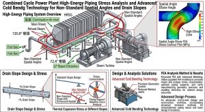
在現代燃氣複循環發電廠(Combined Cycle Power Plant, CCPP)與超臨界火力發電廠的建廠及更新工程中,高壓主蒸汽(Main Steam)與高溫再熱蒸汽(Hot Reheat)管線的佈局設計面臨著極端的空間與物理雙重挑戰。此類高能管線長期運行於攝氏五百七十度至六百二十度的高溫,以及高達一百七十至二百三十巴(bar)的嚴苛高壓環境下,業界標準普遍採用具備優異高溫潛變抗性的潛變強度強化鐵素體鋼(Creep Strength Enhanced Ferritic Steels, CSEF),如 ASTM A335 P91 與 P92 合金鋼。然而,管線在錯綜複雜的廠房鋼構與既有設備之間穿梭時,為閃避空間干涉並嚴格維持 1:100 的連續下傾洩水坡度,極易產生非標準的三維空間角。 In the construction and retrofitting of modern Combined Cycle Power Plants (CCPP) and supercritical thermal power plants, the layout design of high-pressure Main Steam and Hot Reheat piping faces extreme dual challenges in terms of spatial constraints and physical operating conditions. Such high-energy piping operates continuously under severe high-temperature environments (570°C to 620°C) and high pressures (170 to 230 bar). The industry standard widely adopts Creep Strength Enhanced Ferritic Steels (CSEF) with excellent high-temperature creep resistance, such as ASTM A335 P91 and P92 alloy steels. However, as the piping navigates through intricate plant steel structures and existing equipment, avoiding spatial interference while strictly maintaining a continuous downward drainage slope of 1:100 often results in non-standard three-dimensional spatial angles.
傳統工程實務為了解決非標準角度的幾何銜接,常採用「斜切對銲彎頭」(Trimmed Elbows / Miter Cuts)或違法規範公差的「大小縫隙強行組對」(Forced Fit-Up with Uneven Root Gaps)等便宜行事之工法。本研究透過深度論文形式,從流體力學、冶金微觀結構演變、連續損傷力學及最新 ASME B31.1 與 B31J 規範等維度,徹底剖析傳統工法所引發的邊界層剝離、流動加速腐蝕(FAC),以及在細晶熱影響區(FGHAZ)極易爆發的致命性「第四型潛變破裂」(Type IV Cracking)。 To resolve the geometric connections of these non-standard angles, traditional engineering practices often resort to expedient methods such as “Trimmed Elbows” (Miter Cuts) or “Forced Fit-Up with Uneven Root Gaps,” which violate code tolerances. Through an in-depth thesis format, this study thoroughly analyzes the severe consequences caused by these traditional methods from the perspectives of fluid dynamics, metallurgical microstructural evolution, continuum damage mechanics, and the latest ASME B31.1 and B31J codes. These consequences include boundary layer separation, Flow-Accelerated Corrosion (FAC), and the fatal “Type IV Cracking” that easily erupts in the Fine-Grained Heat-Affected Zone (FGHAZ).
為了解決上述傳統工法帶來的隱患,本報告進一步深入探討以 3D 與 5D 數控冷作彎管(CNC Cold Bending)結合感應加熱次臨界彎後熱處理(IH-PBHT)作為現代最佳替代方案之可行性與物理優勢。同時,本研究統整了台灣電廠建廠實務與生命週期成本(LCC)進行綜合比較,為高階動力管線的變更設計與施工提供學理與實務兼具的指導原則。 To address the hidden dangers brought by the aforementioned traditional methods, this report further explores the feasibility and physical advantages of using 3D and 5D CNC Cold Bending combined with Induction Heating Post-Bending Heat Treatment (IH-PBHT) as the optimal modern alternative. Simultaneously, this study integrates Taiwan’s power plant construction practices and Life Cycle Cost (LCC) analysis for a comprehensive comparison, providing guiding principles with both theoretical and practical value for the design modification and construction of high-end power piping.
一、 複循環電廠高壓蒸汽系統之物理工況與洩水坡度設計理念/I. Physical Operating Conditions and Drainage Slope Design Concepts for High-Pressure Steam Systems in CCPP
現代發電廠為追求極致的熱效率並降低碳排放,其熱力循環系統的蒸汽參數已大幅推升至超臨界狀態。在此極端工況下,管線系統的材料選擇與幾何佈局設計,不僅關乎初始建造成本,更直接決定了電廠全生命週期的運轉安全性與可靠度。
To pursue ultimate thermal efficiency and reduce carbon emissions, the steam parameters of thermodynamic cycle systems in modern power plants have been significantly elevated to supercritical states. Under these extreme conditions, the material selection and geometric layout design of piping systems not only relate to initial construction costs but also directly determine the operational safety and reliability throughout the power plant’s entire life cycle.
1.1 高能管線之運行環境與 P91/P92 材料特性分析/1.1 Operating Environment of High-Energy Piping and Material Characteristics of P91/P92
傳統的碳鋼或低合金鋼(如 P11 或 P22)在超過攝氏五百度的環境下會發生快速的塑性降伏與高溫潛變,無法滿足超臨界機組的需求。因此,當前高能蒸汽幹管全面採用 P91(9Cr-1Mo-V-Nb)與 P92(9Cr-1.8W-0.5Mo-V-Nb-B)等高合金馬氏體鋼1。這類鋼材卓越的高溫強度,並非單純來自合金元素的固溶強化,而是高度仰賴其在煉鋼過程中經由精確的正火與回火(Normalizing and Tempering)熱處理所形塑的「回火麻田散鐵基體」(Tempered Martensite Matrix),以及散佈於晶界與板條內部的高密度奈米級析出物2。 Traditional carbon steels or low-alloy steels (such as P11 or P22) undergo rapid plastic yielding and high-temperature creep in environments exceeding 500°C, rendering them inadequate for supercritical unit requirements. Therefore, current high-energy main steam piping comprehensively utilizes high-alloy martensitic steels like P91 (9Cr-1Mo-V-Nb) and P92 (9Cr-1.8W-0.5Mo-V-Nb-B)1. The exceptional high-temperature strength of these steels does not come solely from the solid-solution strengthening of alloy elements. Instead, it heavily relies on the “Tempered Martensite Matrix” shaped through precise normalizing and tempering heat treatments during the steelmaking process, as well as the high-density nanoscale precipitates scattered within grain boundaries and laths2.
這些析出物(主要包含富鉻的 M23C6 型碳化物與 MX 型碳氮化物)在長期高溫服役的過程中,能有效釘扎差排(Dislocation)的移動,並強力阻礙晶界滑移,進而賦予材料極為優異的抗潛變(Creep Resistance)能力5。然而,此種精密的微觀組織對熱循環極度敏感。當管線在現場施工階段再次經歷不當的熱加工或銲接熱循環時,原有的析出強化機制將遭到不可逆的破壞。這種冶金學上的敏感性,正是後續探討傳統銲接工法與冷作彎管技術差異時,最核心的物理基礎。 During long-term high-temperature service, these precipitates (mainly chromium-rich M23C6-type carbides and MX-type carbonitrides) effectively pin dislocation movements and strongly impede grain boundary sliding, thereby endowing the material with extremely excellent creep resistance5. However, this precise microstructure is highly sensitive to thermal cycling. When the piping undergoes improper thermal processing or welding thermal cycles during the on-site construction phase, the original precipitation strengthening mechanism will suffer irreversible damage. This metallurgical sensitivity serves as the core physical foundation for the subsequent discussion on the differences between traditional welding methods and cold bending technology.
1.2 洩水坡度之熱力學必要性與流體動態危害防範/1.2 Thermodynamic Necessity of Drainage Slopes and Prevention of Fluid Dynamic Hazards
在蒸汽管線系統的冷機啟動(Cold Start-up)、暖機啟動(Warm Light-up)或低負載運轉等瞬態操作期間,高達攝氏六百度的高溫蒸汽與相對低溫的管壁進行熱交換,必然會在管內產生大量的冷凝水(Condensate)4。針對此一必然現象,國際管線設計規範與美國電力研究所(EPRI)均嚴格規定,高能幹管必須具備連續且穩定的下傾洩水坡度(Drainage Slope),設計標準通常為 1:100(即每英呎長度下傾八分之一英吋),以利用重力精確引導冷凝水至疏水點(Drain Points)6。 During transient operations such as Cold Start-up, Warm Light-up, or low-load running of the steam piping system, high-temperature steam reaching up to 600°C exchanges heat with the relatively cooler pipe walls, inevitably generating a large amount of condensate inside the pipe4. To address this inevitable phenomenon, international piping design codes and the Electric Power Research Institute (EPRI) strictly stipulate that high-energy main piping must possess a continuous and stable downward drainage slope. The design standard is typically 1:100 (i.e., a drop of one-eighth of an inch per foot of length) to accurately guide the condensate to drain points using gravity6.
若管線因設計不良或施工偏差存在水平盲區或逆向坡度,冷凝水將在管底積聚,引發雙重的致命物理危害。首先是水錘效應與動能衝擊:當流速高達每小時一百四十五公里的高速蒸汽流經積液區時,強大的氣動曳力會捲起水團形成段塞流(Slug Flow),以極高的動能轟擊下游管件,引發毀滅性的次生水錘效應9。其次為熱分層(Thermal Stratification)與熱疲勞龜裂:管底積聚冷水會在管壁上下半部產生巨大的垂直溫度梯度,誘發極大的內部熱應力,導致管線永久性向下彎曲變形(Sagging)。在頻繁的啟停循環下,交變熱應力極易誘發深層的熱疲勞裂紋。實務操作上,鍋爐暖機時必須建立冷凝器高真空度以創造負壓抽吸,這些繁複程序皆是為了配合洩水坡度,確保冷凝水徹底排除7。 If the piping has horizontal blind spots or reverse slopes due to poor design or construction deviations, condensate will accumulate at the bottom, triggering dual fatal physical hazards. The first is the water hammer effect and kinetic impact: when high-speed steam flowing up to 145 kilometers per hour passes through the accumulated liquid zone, strong aerodynamic drag will roll up the water mass into a slug flow, bombarding downstream fittings with extremely high kinetic energy and triggering a devastating secondary water hammer effect9. The second is thermal stratification and thermal fatigue cracking: cold water accumulating at the bottom of the pipe creates a massive vertical temperature gradient between the upper and lower halves of the pipe wall, inducing immense internal thermal stress and causing permanent downward sagging deformation. Under frequent start-stop cycles, alternating thermal stresses easily induce deep thermal fatigue cracks. In practical operations, a high vacuum must be established in the condenser during boiler warm-up to create negative pressure suction; these complex procedures are designed to cooperate with the drainage slope to ensure the thorough elimination of condensate7.
1.3 空間干涉與非標準角度之工程挑戰/1.3 Spatial Interference and Engineering Challenges of Non-Standard Angles
在新建燃氣複循環電廠或舊廠更新(Retrofit)工程中,蒸汽主幹管必須在密集的廠房鋼構、既有發電設備與通風管線之間穿梭。為了閃避結構干涉,同時又必須在三維空間中維持百分之一的洩水坡度,管線的轉折角度極少能剛好吻合標準鍛造彎頭的四十五度或九十度4。 In new CCPP projects or plant retrofit engineering, the main steam piping must navigate through dense plant steel structures, existing power generation equipment, and ventilation pipelines. To avoid structural interference while maintaining a one-percent drainage slope in three-dimensional space, the turning angles of the piping rarely perfectly match the 45 or 90 degrees of standard forged elbows4.
工程設計師與施工團隊經常面臨如四十四點三度、八十九點三度或九十一點二度等非標準空間角。為了解決幾何銜接問題,早期工程界發展出多種傳統工法,但這些工法在解決角度的同時,卻在力學與冶金領域埋下了嚴重的長期失效隱患4。 Engineering designers and construction teams frequently encounter non-standard spatial angles such as 44.3°, 89.3°, or 91.2°. To resolve the geometric connection problems, the early engineering community developed various traditional methods; however, while solving the angle issue, these methods planted severe long-term failure hazards in the fields of mechanics and metallurgy4.
二、 傳統非標準角度工法之流體力學與冶金應力深度剖析/II. In-Depth Analysis of Fluid Dynamics and Metallurgical Stress in Traditional Non-Standard Angle Methods
面對錯綜複雜的非標準空間角,傳統工程實務中最常採用的手段為「斜切對銲彎頭」(Trimmed Elbows 或 Miter Cuts)以及具備高度爭議的「大小縫隙強行組對」(Forced Fit-Up)。這兩種工法嚴重破壞了管線的流體動力學穩定性與微觀冶金結構,成為超臨界電廠營運期的重大安全隱憂。
Faced with intricate non-standard spatial angles, the most commonly used methods in traditional engineering practice are “Trimmed Elbows” (or Miter Cuts) and the highly controversial “Forced Fit-Up.” These two methods severely damage the fluid dynamic stability and microscopic metallurgical structure of the piping, becoming major safety concerns during the operational phase of supercritical power plants.
2.1 斜切對銲彎頭在兩相流場中之極端效應/2.1 Extreme Effects of Trimmed Miter Elbows in Two-Phase Flow Fields
斜切彎頭工法係將預製的標準 1.5D 鍛造對銲彎頭進行現場機械裁切,破壞其原有的幾何曲率連續性後,再與直管進行全滲透對銲拼接。根據 ASME B31.1 與 B31.3 規範,此類斜切彎管的設計受限於相鄰管段夾角不得超過二十二點五度,且其短邊長度必須大於六倍管壁厚度(B < 6tn),彎曲半徑需滿足R ≧ 3D(拼接段數小於等於三段時)等條件5。然而,即便符合最低規範要求,斜切彎頭在超臨界蒸汽的兩相流場(Two-phase Flow)中仍會引發極端負面效應。 The miter cut elbow method involves mechanically trimming pre-fabricated standard 1.5D forged butt-welded elbows on-site, destroying their original geometric curvature continuity, and then splicing them with straight pipes using full penetration butt welding. According to ASME B31.1 and B31.3 codes, the design of such miter bends is restricted by conditions such as the included angle between adjacent pipe sections not exceeding 22.5 degrees, the short edge length must be greater than six times the pipe wall thickness (B < 6tn), and the bend radius must satisfy R ≧ 3D (when the number of spliced segments is three or less)5. However, even when meeting the minimum code requirements, trimmed elbows still trigger extreme negative effects in the two-phase flow fields of supercritical steam.
首先,斜切端點形成的幾何曲率斷層會引發複雜的三維流場分離。在雷諾數(Re)高達一百三十三萬至五百八十一萬的亂流狀態下,流線的突然偏折產生了極大的逆壓梯度,導致邊界層剝離,並在轉角內側形成巨大的低速回流區與分離泡(Separation Bubble)4。其次為迪恩渦流(Dean Vortices)與流動加速腐蝕(FAC):流體通過斜切彎頭時受離心力驅使,橫截面上形成強烈的雙股反向旋轉渦流6。劇烈的擾流與高剪切應力會不斷集中於斜切銲縫處,持續刮除 P91 鋼管內壁的保護性氧化膜,引發劇烈的流動加速腐蝕與沖刷腐蝕4。此外,幾何銳角會導致局部靜壓急遽下降,引發相變閃蒸與空穴效應(Cavitation),產生的微射流會持續轟擊脆弱的拼接銲縫,造成微觀金屬疲勞剝離。 First, the geometric curvature fault formed at the trimmed end induces complex three-dimensional flow separation. Under highly turbulent states with a Reynolds number (Re) reaching 1.33 to 5.81 million, the sudden deflection of streamlines creates a massive adverse pressure gradient, causing boundary layer separation and forming a huge low-speed recirculation zone and separation bubble at the inner corner4. Second are Dean Vortices and Flow-Accelerated Corrosion (FAC): driven by centrifugal force as fluid passes through the trimmed elbow, strong dual counter-rotating vortices form on the cross-section6. Violent turbulence and high shear stress continuously concentrate at the miter weld, constantly scraping off the protective oxide film on the inner wall of the P91 steel pipe, triggering severe FAC and erosion-corrosion4. Furthermore, the geometric sharp angles cause a sharp drop in local static pressure, triggering phase-change flashing and cavitation; the resulting micro-jets continuously bombard the fragile spliced weld, causing microscopic metal fatigue flaking.
2.2 銲接熱循環與第四型潛變破裂(Type IV Cracking)之連續損傷機制/2.2 Welding Thermal Cycles and the Continuum Damage Mechanism of Type IV Cracking
除了流體動力學的破壞,斜切銲接對 P91/P92 材料造成的冶金破壞更是致命。此工法等同於在系統彎矩與熱膨脹應力最集中的轉折處,人為增加了一道全滲透銲縫。根據 EPRI 與國際材料學界研究,CSEF 鋼經歷銲接熱循環時,會在母材兩側形成微觀組織截然不同的熱影響區(HAZ)2。 Beyond fluid dynamic destruction, the metallurgical damage caused by miter welding to P91/P92 materials is even more fatal. This method is equivalent to artificially adding a full-penetration weld at the turning point where system bending moments and thermal expansion stresses are most concentrated. According to research by EPRI and the international materials community, when CSEF steel undergoes welding thermal cycles, it forms Heat-Affected Zones (HAZ) with distinctly different microstructures on both sides of the base metal2.
距離鎔合線稍遠的區域,其經歷的峰值溫度介於沃斯田鐵相變開始溫度(AC1)與終了溫度(AC3)之間,被稱為「細晶熱影響區」(FGHAZ)與「臨界區」(ICHAZ)8。在此區域內,材料發生不完全相變,晶粒嚴重再結晶與細化。最致命的是,負責釘扎差排的析出物在高溫下發生部分溶解或劇烈粗化,徹底喪失強化效應,形成一條沿著銲縫輪廓分佈的「軟化帶」(Soft Zone)4。在長期的交變熱應力與內壓環向應力拉扯下,潛變空孔(Creep Cavities)會在此軟化帶的舊晶界處大量形核並緩慢成長。由於這類微觀損傷極具隱蔽性,往往在突破臨界點後迅速聚集成宏觀微裂紋並急速擴展,導致管線無預警斷裂。此發生於 HAZ 外緣的失效機制即為「第四型潛變破裂」2。 The area slightly further from the fusion line experiences peak temperatures between the austenite transformation start temperature (AC1) and finish temperature (AC3), and is known as the Fine-Grained HAZ (FGHAZ) and Intercritical HAZ (ICHAZ)8. In this region, the material undergoes incomplete phase transformation, resulting in severe grain recrystallization and refinement. Most fatally, the precipitates responsible for pinning dislocations undergo partial dissolution or severe coarsening at high temperatures, completely losing their strengthening effect and forming a “Soft Zone” distributed along the weld contour4. Under the long-term pulling of alternating thermal stresses and internal hoop stresses, creep cavities nucleate profusely and grow slowly at the prior austenite grain boundaries within this soft zone. Because such microscopic damage is highly concealed, it often rapidly aggregates into macroscopic microcracks and propagates swiftly after breaching a critical point, leading to unannounced piping rupture. This failure mechanism occurring at the outer edge of the HAZ is known as “Type IV Cracking”2.
2.3 大小縫隙強行組對之違規操作與殘餘應力疊加/2.3 Violating Operations of Forced Fit-Up with Uneven Root Gaps and Residual Stress Superposition
為了逃避繁瑣的機械裁切,少數施工現場會採用極具危險性的便宜行事作法:直接在管口的對銲接口處刻意製造一側縫隙極大、另一側幾乎貼合的「大小縫」,再利用千斤頂施加強大外力,強行扳折管線以湊出角度,最後在極端應力狀態下強行施銲8。 To evade tedious mechanical trimming, a minority of construction sites adopt highly dangerous expedient practices: deliberately creating an “uneven root gap”—with one side exceptionally wide and the other almost touching—directly at the butt-weld interface of the pipe ends, then applying tremendous external force using jacks to forcibly bend the pipe to the desired angle, and finally welding forcefully under extreme stress conditions8.
此作法嚴重違反 ASME 動力管線規範對組對公差的嚴格要求。規範明定錯邊量(Hi-Lo Gap)上限通常為 1.6 毫米或最薄管壁厚度的 25% 兩者之較小值14。強行製造大小縫不僅導致錯邊量嚴重超標,極端不均勻的根部間隙更會誘發未鎔合或嚴重燒穿等致命體積性缺陷。同時,強行扳折特厚壁 P91 鋼管會在銲道根部鎖死(Lock-in)巨大的初始殘餘彎矩。當系統啟動至高溫時,強大的熱膨脹位移應力與此殘餘應力產生災難性疊加,極易在短短數次啟停循環內誘發低週期疲勞裂紋,最終導致蒸汽洩漏甚至爆管9。 This practice severely violates the strict requirements for fit-up tolerances in the ASME power piping codes. The code specifies that the maximum misalignment (Hi-Lo Gap) is typically the lesser of 1.6 mm or 25% of the thinnest pipe wall thickness14. Forcibly creating uneven gaps not only causes the misalignment to severely exceed limits, but the extremely uneven root gap also induces fatal volumetric defects such as lack of fusion or severe burn-through. Simultaneously, forcibly bending extra-heavy wall P91 steel pipes locks in massive initial residual bending moments at the weld root. When the system starts up to high temperatures, the powerful thermal expansion displacement stress superimposes disastrously with this residual stress, easily inducing low-cycle fatigue cracks within just a few start-stop cycles, ultimately leading to steam leakage or even pipe bursting9.
三、 先進替代方案:數控冷作彎管與次臨界彎後熱處理技術/III. Advanced Alternative Solutions: CNC Cold Bending and Subcritical Post-Bending Heat Treatment Technology
有鑑於傳統斜切對銲與強行組對工法在流場擾動與微觀冶金上的雙重致命缺陷,當前國際級工程統包商(EPC)與先進設計規範已全面將設計思維轉向「能彎不銲」的理念9。針對 P91/P92 高能管線,採用三維數控一體成型冷作彎管(CNC Cold Bending)並搭配感應加熱次臨界彎後熱處理(IH-PBHT),已成為最佳現代方案。
In view of the dual fatal flaws of traditional miter welding and forced fit-up methods in terms of flow field turbulence and microscopic metallurgy, current international Engineering, Procurement, and Construction (EPC) contractors and advanced design codes have comprehensively shifted their design philosophy towards the concept of “Bend, Don’t Weld”9. For P91/P92 high-energy piping, utilizing three-dimensional integrated CNC Cold Bending combined with Induction Heating Post-Bending Heat Treatment (IH-PBHT) has become the optimal modern solution.
3.1 大半徑冷作彎管之幾何平順度與流體力學優勢/3.1 Geometric Smoothness and Fluid Dynamic Advantages of Large-Radius Cold Bending
現代冷作彎管技術通常採用三倍(3D)或五倍(5D)公稱管徑的彎曲半徑,遠大於傳統鍛造彎頭的 1.5D 半徑9。大半徑加上一體成型的無縫幾何連續性,徹底消除了曲率突變,有效防止邊界層剝離與分離泡的產生,使迪恩渦流強度大幅降低。超臨界蒸汽得以以極低的壓力損失平順通過,大幅降低 FAC 風險7。 Modern cold bending technology typically employs bending radii of three times (3D) or five times (5D) the nominal pipe diameter, which is much larger than the 1.5D radius of traditional forged elbows9. The large radius combined with the seamless geometric continuity of a one-piece formation completely eliminates curvature mutations, effectively preventing boundary layer separation and the formation of separation bubbles, thereby significantly reducing the intensity of Dean Vortices. Supercritical steam can pass smoothly with minimal pressure loss, substantially lowering the risk of FAC7.
大半徑的平順過渡能有效吸收熱膨脹位移,防止產生逆向坡度,確保冷凝水能順利受重力引導至疏水點,徹底消除積水引發水錘與熱分層的條件,完美契合洩水坡度的設計初衷9。最核心的優勢在於轉折處完全沒有全滲透銲縫,從根本上消除了脆弱的細晶熱影響區(FGHAZ),徹底杜絕了第四型潛變破裂發生機率4。 The smooth transition of the large radius can effectively absorb thermal expansion displacements and prevent the generation of reverse slopes, ensuring that condensate can be smoothly guided by gravity to drain points. This thoroughly eliminates the conditions for water hammer and thermal stratification caused by water accumulation, perfectly aligning with the original design intent of the drainage slope9. The most core advantage lies in the complete absence of full-penetration welds at the turning point, which fundamentally eliminates the fragile FGHAZ and thoroughly eradicates the probability of Type IV Cracking4.
3.2 ASME B31.1 規範之冷作應變限制與微觀相變溫度下降現象/3.2 Cold Strain Limits of ASME B31.1 Code and the Phenomenon of Microscopic Phase Transformation Temperature Drop
儘管消除了銲縫,P91/P92 高合金鋼材在冷彎塑形過程中會承受巨大塑性變形。依據 ASME B31.1 規範,對於 P-No. 15E 群組材料,若冷作形變率超過百分之五,強制規定必須實施後續熱處理以恢復韌性15。冷彎應變率 ϵ 的近似公式為 ϵ=50D/R 或 ϵ=r/R×100% 15。對於常見的 3D 彎管,其應變率往往高達 16% 以上,遠超免熱處理極限值。 Although welds are eliminated, P91/P92 high-alloy steels undergo immense plastic deformation during the cold bending shaping process. According to the ASME B31.1 code, for P-No. 15E group materials, if the cold forming strain rate exceeds 5%, it is mandatory to implement subsequent heat treatment to restore toughness15. The approximate formula for the cold bending strain rate ϵ is ϵ=50D/R or ϵ=r/R×100% 15. For common 3D bends, the strain rate often reaches over 16%, far exceeding the threshold for exemption from heat treatment.
前瞻冶金研究指出,經歷大於 5% 塑性應變後,材料內部累積的高密度差排會在加熱時形成大量次晶界。這些次晶界為沃斯田鐵形核提供了偏好位置,導致大應變冷作 P91/P92 材料的 AC1 與 AC3 溫度較原始母材顯著下降了 10°C 至 15°C18。未變形的 P91 鋼之 AC1 約為 800°C~830°C,冷彎後可能降至低於 800°C9。 Forward-looking metallurgical research indicates that after experiencing plastic strain greater than 5%, the high-density dislocations accumulated inside the material will form a large number of subgrain boundaries during heating. These subgrain boundaries provide preferential nucleation sites for austenite, causing the AC1 and AC3 temperatures of highly strained cold-worked P91/P92 materials to drop significantly by 10°C to 15°C compared to the original base metal18. The AC1 of undeformed P91 steel is approximately 800°C~830°C, and after cold bending, it may drop below 800°C9.
3.3 感應加熱彎後熱處理(IH-PBHT)與 Larson-Miller 參數控制模型/3.3 Induction Heating Post-Bending Heat Treatment (IH-PBHT) and the Larson-Miller Parameter Control Model
為因應已下降的 AC1 相變溫度,避免熱處理局部超溫導致材料部分沃斯田鐵化而喪失潛變抗力,業界全面導入具備閉迴路精準控溫的感應加熱(IH)技術來執行次臨界彎後熱處理9。工程師利用 Larson-Miller 參數(LMP)來定量評估熱處理綜合效應: To respond to the lowered AC1 phase transformation temperature and avoid localized over-temperature during heat treatment that leads to partial austenitization and loss of creep resistance, the industry has comprehensively introduced Induction Heating (IH) technology with closed-loop precise temperature control to execute subcritical post-bending heat treatment9. Engineers utilize the Larson-Miller Parameter (LMP) to quantitatively evaluate the comprehensive effect of the heat treatment:
LMP=T×(logt+C)×10-3
(其中 T 為絕對溫度,t 為持溫時間,C 為材料常數,P91 鋼通常為 21)14。 (Where T is the absolute temperature, t is the holding time, and C is a material constant, typically 21 for P91 steel)14.
結合 ASME B31.1 要求,IH-PBHT 的絕對溫度上限嚴格設定在 800°C 以下14。實務最佳化模型將靶溫設定在 760°C 至 780°C 之間14,透過控制時間使 LMP 累積至 ≧ 21(建議達 22),確保硬度控制在 190~265 HV 之間,完美恢復潛變強度並避免應力腐蝕破裂風險。降溫速率亦嚴格限制在 55°C/hr 以下14。 Integrating ASME B31.1 requirements, the absolute temperature upper limit for IH-PBHT is strictly set below 800°C14. The practical optimization model sets the target temperature between 760°C and 780°C14. By controlling the time, the LMP is accumulated to ≧ 21 (recommended to reach 22) to ensure hardness is controlled between 190 and 265 HV, perfectly restoring creep strength and avoiding the risk of stress corrosion cracking. The cooling rate is also strictly limited to below 55°C/hr14.
3.4 CCPP 選擇 3D 與 5D 大彎管之幾何流體與應力優勢/3.4 Geometric, Fluid, and Stress Advantages of Selecting 3D and 5D Large Bends in CCPP
相較於 1.5D 彎頭,3D 與 5D 彎管的幾何曲率更為平緩,徹底消除了產生邊界層剝離與強烈迪恩渦流的物理條件,將流動加速腐蝕(FAC)風險降至最低4。在應力解析上,以 4″ XXS 特厚壁 P91/P92 管線為例,其 3D 冷作彎管的無因次柔性特徵值高達 2.210,理論面內應力強度因子(SIF)大幅降低逾 37% 4。一體成型特性消除了熱影響區軟化帶,成為高壓管線系統變更設計時的首選6。 Compared to 1.5D elbows, the geometric curvature of 3D and 5D bends is much gentler, completely eliminating the physical conditions for boundary layer separation and strong Dean vortices, thereby minimizing the risk of Flow-Accelerated Corrosion (FAC)4. In stress analysis, taking a 4″ XXS extra-heavy wall P91/P92 pipe as an example, the dimensionless flexibility characteristic value of its 3D cold bend is as high as 2.210, and the theoretical in-plane Stress Intensification Factor (SIF) is significantly reduced by over 37% 4. The integrated forming characteristic eliminates the heat-affected zone soft band, making it the first choice for design modifications in high-pressure piping systems6.
四、 基於 2026 ASME B31J 之管系應力與柔性厚度分析/IV. Piping System Stress and Flexibility Thickness Analysis Based on 2026 ASME B31J
決定採用 3D 或 5D 冷作彎管取代傳統 1.5D 彎頭時,必須重新進行嚴謹的管系應力分析。ASME B31J 規範的引入,為管線柔性因子與應力集中因子的計算帶來了革命性突破。
When deciding to adopt 3D or 5D cold bends to replace traditional 1.5D elbows, a rigorous piping system stress analysis must be re-conducted. The introduction of the ASME B31J code has brought a revolutionary breakthrough to the calculation of piping flexibility factors and stress intensification factors.
4.1 管壁厚度設計之應力基礎與腐蝕餘裕/4.1 Stress Basis and Corrosion Allowance in Pipe Wall Thickness Design
依據 ASME B31.1 規範第 104.1.2 節,直管承受內壓的最小需求壁厚(tm)計算公式為: According to Section 104.1.2 of the ASME B31.1 code, the formula for calculating the minimum required wall thickness (tm) of a straight pipe subjected to internal pressure is:
tm=[P⋅D/(2⋅(S⋅E+P⋅y) )]+A
(P 為內部設計壓力,D 為管外徑,S 為容許應力,E 為銲接效率係數,y 為溫度係數,A 包含腐蝕餘裕)3。 (Where P is the internal design pressure, D is the pipe outside diameter, S is the allowable stress, E is the weld joint efficiency factor, y is the temperature coefficient, and A includes the corrosion allowance)3.
以 CCPP 常見高溫疏水管徑為例,常需採用 NPS 4″ XXS 特厚壁規格(徑厚比 Do/T 僅約 6.68),這種極端的厚壁特性對後續柔性分析影響深遠6。 Taking common high-temperature drain piping diameters in CCPP as an example, NPS 4″ XXS extra-heavy wall specifications are often required (with a diameter-to-thickness ratio Do/T of only about 6.68). This extreme thick-wall characteristic profoundly impacts subsequent flexibility analysis6.
4.2 B31J 對應力強度與持續應力之物理機制解耦及實證對比/4.2 B31J Decoupling of Physical Mechanisms for SIF and SSI and Empirical Comparison
最新版 ASME B31J 規範將「應力強度因子」(SIF)與「持續應力指數」(SSI)在物理機制上徹底解耦。SSI 評估抗整體塑性崩塌能力(對 P91 潛變壽命至關重要),而 SIF 評估局部循環負載下的疲勞裂紋風險。彎管橫截面受彎矩壓扁的卡門橢圓化效應(Karman Effect),其柔性程度取決於無因次特徵值 h=T⋅R1 /r22。 The latest edition of the ASME B31J code completely decouples the “Stress Intensification Factor” (SIF) and the “Sustained Stress Index” (SSI) in their physical mechanisms. SSI evaluates the ability to resist overall plastic collapse (crucial for P91 creep life), while SIF evaluates the risk of fatigue cracking under local cyclic loading. The Karman Effect, where the cross-section of a bend flattens under bending moments, determines flexibility based on the dimensionless characteristic value h=T⋅R1 /r22.
我們以 NPS 4″ XXS 特厚壁 P91 鋼管為例進行力學特徵比較: We take NPS 4″ XXS extra-heavy wall P91 steel pipe as an example to compare mechanical characteristics:
| B31J 物理參數與運算指標 / B31J Physical Parameters & Indicators | 傳統 1.5D 對銲彎頭 / Traditional 1.5D Miter Cut Elbow (R1=6 吋/inch) | 3D 大半徑冷作彎管 / 3D Large Radius Cold-Bent Pipe (R1=12 吋/inch) | 力學對比與解析意義 / Mechanical Comparison & Analytical Significance |
| 無因次柔性特徵值 (h) / Dimensionless Flexibility Characteristic (h) | 1.105 | 2.210 | 3D 彎管因彎曲半徑倍增,抗變形能力更強。 / The 3D bend has a doubled radius, offering stronger deformation resistance. |
| 理論面內 SIF (iin,theoretical) / Theoretical In-plane SIF (iin,theoretical) | 0.842 | 0.530 | 3D 彎管理論應力集中程度較 1.5D 大幅降低逾 37%。 / Theoretical stress concentration of 3D bend is reduced by over 37% compared to 1.5D. |
| B31J 修正後 SIF (iin,) / B31J Modified SIF (iin) | 1.0 | 1.0 | 基於法規安全底線,軟體中皆強制收斂至 1.0。 / Based on code safety baselines, both are forced to converge to 1.0 in software. |
| 理論柔性因子 (ktheoretical) / Theoretical Flexibility Factor (ktheoretical) | 1.176 | 0.588 | 極端厚壁抑制橢圓化效應,理論柔性極低。 / Extreme thickness suppresses the ovalization effect, resulting in very low theoretical flexibility. |
對於 XXS 特厚壁管線,強大壁厚抑制了卡門橢圓化效應,使軟體運算強制收斂至剛體數值 1.0。然而探討未截斷的理論數值,3D 彎管真實的幾何應力集中程度遠低於傳統彎頭。結合冷作消除 HAZ 的優勢,3D/5D 冷作彎管具備壓倒性的物理安全性。 For XXS extra-heavy wall piping, the massive wall thickness suppresses the Karman ovalization effect, causing software calculations to force convergence to a rigid body value of 1.0. However, when exploring the untruncated theoretical values, the true geometric stress concentration of the 3D bend is far lower than that of the traditional elbow. Combined with the advantage of cold bending eliminating the HAZ, 3D/5D cold-bent pipes possess overwhelming physical safety.
五、 台灣電廠建廠實務經驗與生命週期成本(LCC)綜合比較/V. Comprehensive Comparison of Taiwan Power Plant Construction Practice and Life Cycle Cost (LCC)
台灣在積極推動能源轉型、大規模興建燃氣複循環機組的過程中,累積了豐富的建廠與施工經驗。台灣獨特的建廠環境,進一步凸顯了先進冷作彎管技術的必要性。
In the process of actively promoting energy transition and constructing large-scale CCPP units, Taiwan has accumulated rich experience in plant construction and execution. Taiwan’s unique construction environment further highlights the necessity of advanced cold bending technology.
5.1 台灣建廠環境之特殊性與 EPC 施工痛點/5.1 Uniqueness of Taiwan’s Construction Environment and EPC Construction Pain Points
台灣 CCPP 專案常面臨廠區腹地狹小、鋼構密集的困境,管線維持洩水坡度時遭遇非標準角度干涉的問題層出不窮9。同時,面臨高階電銲技術人力短缺且工資高昂的窘境。現場全滲透銲接 P91/P92 程序異常繁瑣,需嚴格預熱、去氫烘烤及耗時長達 12 小時的 PWHT8。斜切彎頭工法不僅拖垮進度,且易產生缺陷。 Taiwan’s CCPP projects often face the dilemma of narrow plant sites and dense steel structures, with non-standard angle interference problems constantly emerging when piping maintains drainage slopes9. Simultaneously, there is a severe shortage of high-end welding technicians and exorbitant labor costs. The on-site full-penetration welding procedure for P91/P92 is exceptionally cumbersome, requiring strict preheating, hydrogen bakeout, and a time-consuming PWHT of up to 12 hours8. The miter elbow method not only drags down project progress but also easily generates defects.
5.2 備料適時性(Just-In-Time)與無損檢測(NDE)成本對比/5.2 Supply Timeliness (Just-In-Time) and Non-Destructive Examination (NDE) Cost Comparison
客製特殊角度的 1.5D 彎頭向海外下單交期長達數月15。相反地,冷作彎管技術可直接提取現場 P91 直管進行加工,具備「零天待料」的靈活性,成為突破空間干涉的極佳「救火對策」15。 Ordering customized special-angle 1.5D elbows from overseas entails a lead time of several months15. Conversely, cold bending technology can directly utilize on-site P91 straight pipes for processing, offering the flexibility of “zero-day waiting” and becoming an excellent “firefighting countermeasure” to break through spatial interference15.
在檢測成本方面,斜切彎頭迫使每一處增加兩道銲縫,需 100% 執行昂貴的相控陣列超音波(PAUT)或射線檢測(RT)1。冷作彎管因無銲縫,僅需簡單表面液滲(PT)或磁粒檢測(MT)輔以壁厚減薄量測,檢驗費用與耗時呈倍數下降7。 Regarding inspection costs, miter elbows force the addition of two welds at every joint, requiring 100% execution of expensive Phased Array Ultrasonic Testing (PAUT) or Radiographic Testing (RT)1. Because cold-bent pipes are seamless, they only require simple Liquid Penetrant Testing (PT) or Magnetic Particle Testing (MT) supplemented by wall thinning measurements, resulting in exponentially reduced inspection costs and time7.
5.3 營運維護與風險成本(OPEX)及數位化履歷之合規優勢/5.3 Operational Expenditure (OPEX), Risk Costs, and Compliance Advantages of Digital Traceability
從電廠生命週期成本(LCC)評估,冷作彎管的長期 OPEX 優勢顯著。傳統斜切彎管在營運期極易因 FAC 與 HAZ 軟化帶引發破管隱患9。對於大型 CCPP 機組,非計畫停機造成的發電損失每日高達數百萬元。冷作彎管消除了高風險銲縫,保障長期 LCC 經濟效益7。 From the perspective of Life Cycle Cost (LCC) evaluation, the long-term OPEX advantages of cold bends are significant. Traditional miter bends are highly prone to tube rupture hazards caused by FAC and HAZ soft zones during the operational phase9. For large CCPP units, power generation losses caused by unplanned outages can reach millions of dollars daily. Cold bends eliminate high-risk welds, safeguarding long-term LCC economic benefits7.
因應 ASME B31.1 最新規範(Appendix Q/R),台灣先進加工廠已將冷彎與熱處理流程數位化8。透過 QR Code 與 IoT 綁定材料證明書(MTR)及 IH-PBHT 溫度曲線,防範人為竄改,確保每一管件百分之百的可追溯性,為 EPC 統包商提供極高的合規確證度14。 In response to the latest ASME B31.1 code (Appendix Q/R), advanced processing plants in Taiwan have digitized the cold bending and heat treatment processes8. By binding Material Test Reports (MTR) and IH-PBHT temperature curves via QR Code and IoT, manual tampering is prevented, ensuring 100% traceability for every fitting and providing EPC contractors with an extremely high degree of compliance certainty14.
5.4 潁璋工程冷作彎管工法之實務操作與專案效益/5.4 Practical Operations and Project Benefits of Yingzhang Engineering’s Cold Bending Method
以位於高雄林園的潁璋工程為例,其在 CCPP 管線工程中展現了先進冷作彎管的實質效益21。潁璋提供專業 3D 與 5D 冷作彎管技術,相較於熱彎,室溫冷彎能最大程度保留 P91/P92 原有高溫潛變強度,免除高溫加熱程序並確保表面品質22。透過直接取用現場直管,實現「零天待料」(Just-In-Time),大幅縮短工期並免除繁瑣 PWHT15。潁璋工程從技術諮詢到品質管控,為 EPC 統包商提供了在地化與數位化合規的完美解決方案16。 Taking Yingzhang Engineering located in Linyuan, Kaohsiung, as an example, it has demonstrated the substantial benefits of advanced cold bending in CCPP piping projects21. Yingzhang provides professional 3D and 5D cold bending technology. Compared to hot bending, room-temperature cold bending maximizes the retention of the original high-temperature creep strength of P91/P92, eliminates the high-temperature heating procedure, and ensures surface quality22. By directly utilizing on-site straight pipes, it achieves “zero-day waiting” (Just-In-Time), significantly shortening the construction period and eliminating tedious PWHT15. From technical consultation to quality control, Yingzhang Engineering provides EPC contractors with a perfect solution that is both localized and digitally compliant16.
六、 結論/VI. Conclusion
本研究綜合流體力學、微觀冶金學、法規應力解析與工程經濟實務,對 CCPP 高能管線非標準空間角與洩水坡度的設計與施工工法確立以下核心結論:
By integrating fluid dynamics, microscopic metallurgy, code stress analysis, and engineering economic practice, this study establishes the following core conclusions regarding the design and construction methods of non-standard spatial angles and drainage slopes for CCPP high-energy piping:
- 傳統工法之物理與冶金缺陷不可逆轉:面對洩水坡度與空間角挑戰,傳統的「斜切對銲彎頭」與違規的「大小縫隙強行組對」工法,嚴重破壞流場平順度,引發 FAC;在冶金上更導入了脆弱的 FGHAZ,埋下第四型潛變破裂隱患,已無法滿足現代超臨界系統的安全需求。Irreversible Physical and Metallurgical Flaws of Traditional Methods: Facing the challenges of drainage slopes and spatial angles, traditional “Miter Cut Elbows” and violating “Forced Fit-Up” methods severely destroy flow field smoothness and trigger FAC; metallurgically, they introduce the fragile FGHAZ, planting the hidden danger of Type IV Cracking, which can no longer meet the safety demands of modern supercritical systems.
- 大半徑冷作彎管與 IH-PBHT 之卓越適配性:3D/5D 數控冷作彎管一體成型維持了完美的流體力學連續性,確保洩水防護功能,並消弭了轉折處的銲縫。嚴格遵循規範執行精確的感應加熱彎後熱處理(IH-PBHT),可完美修復微觀組織退化,兼顧潛變抗力與系統柔性。Excellent Adaptability of Large-Radius Cold Bends and IH-PBHT: 3D/5D CNC cold bends are formed in one piece, maintaining perfect fluid dynamic continuity, ensuring drainage protection functions, and eliminating welds at turning points. By strictly following codes to execute precise IH-PBHT, microstructural degradation can be perfectly restored, balancing creep resistance and system flexibility.
- 工程經濟實務與法規發展之必然趨勢:結合台灣建廠實務與 LCC 分析證明,冷作彎管靈活性與無損檢測成本巨幅下降完美解決了缺工與空間干涉痛點。隨著 B31J 普及與數位化追溯強制推行,「能彎不銲」理念已成為高階動力管線設計與施工無可逆轉的先進範式。Inevitable Trend of Engineering Economic Practice and Code Development: Combined with Taiwan’s construction practices and LCC analysis, it is proven that the flexibility of cold bends and the massive reduction in NDE costs perfectly solve the pain points of labor shortages and spatial interference. With the popularization of B31J and the mandatory implementation of digital traceability, the “Bend, Don’t Weld” concept has become an irreversible advanced paradigm for the design and construction of high-end power piping.
參考文獻/References
- Piping Materials and Allowable Stress in ASME B31.1 Power Piping, https://mypipingnotes.com/asme-b31-1-materials-allowable-stress/
- Type IV Cracking of Weldments in Enhanced Ferritic Steels – TWI, https://www.twi-global.com/technical-knowledge/published-papers/review-of-type-iv-cracking-of-weldments-in-9-12cr-creep-strength-enhanced-ferritic-steels/
- ASME B31.1 Pressure Design Explained: Pipe Thickness, https://mypipingnotes.com/asme-b31-1-pressure-design/
- https://yz-pipe-bending.com.tw/%E5%9F%BA%E6%96%BC-2026-asme-b31j-%E8%A6%8F%E7%AF%84%EF%BC%9Ap91-%E9%AB%98%E5%A3%93%E8%92%B8%E6%B1%BD%E7%AE%A1%E7%B7%9A%E6%B4%A9%E6%B0%B4%E5%9D%A1%E5%BA%A6%E8%A8%AD%E8%A8%88%E6%8E%A1%E5%8F%96%E5%B0%8D/
- Mitered Elbow Pressure Calculations | PDF | Pipe (Fluid Conveyance), https://www.scribd.com/document/219412375/MiterB1a
- Piping and Pipeline Bends – EPCM Holdings, https://epcmholdings.com/piping-and-pipeline-bends/
- https://yz-pipe-bending.com.tw/%E8%A4%87%E5%BE%AA%E7%92%B0%E9%9B%BB%E5%BB%A0%E9%AB%98%E5%A3%93%E8%92%B8%E6%B1%BD%E7%AE%A1%E7%B7%9A%E6%B4%A9%E6%B0%B4%E5%9D%A1%E5%BA%A6%E8%A8%AD%E8%A8%88%E8%88%87%E7%AE%A1%E4%BB%B6%E5%B7%A5%E6%B3%95/
- ASME B31.1-2024: Power Piping [New] [Changes] – The ANSI Blog, https://blog.ansi.org/ansi/asme-b31-1-2024-power-piping-changes/
- ASME B31.1 Power Piping 2018 Changes – Bradley Sawler, https://www.bradleysawler.com/engineering/asme-b31-1-power-piping-2018-changes/
- Free Miter Bend Calculator — Mitered Elbow Flat Pattern & 3D Layout, https://pipecalculators.com/mitered-elbow-layout.html
- ASME CALCULATION FOR MITER BEND – ExcelCalcs, https://www.excelcalcs.com/calcs/repository/Fluids/Piping/ASME-CALCULATION-FOR-MITER-BEND/
- Review of Type IV Cracking in Piping Welds – EPRI, https://restservice.epri.com/publicdownload/TR-108971/0/Product
- Creep-Fatigue Life Properties and Its Life Prediction Method for, https://www.jstage.jst.go.jp/article/jsms/74/2/74_75/_article/-char/en
- Weld Joint Preparation According to ASME B31.3 and B31.1, https://gbcspa.com/en/weld-joint-preparation-asme-b31/
- CCPP 高能管線變更設計之適時性對策:以4″ XXS P91/P92 冷作彎, https://yz-pipe-bending.com.tw/ccpp-%E9%AB%98%E8%83%BD%E7%AE%A1%E7%B7%9A%E8%AE%8A%E6%9B%B4%E8%A8%AD%E8%A8%88%E4%B9%8B%E9%81%A9%E6%99%82%E6%80%A7%E5%B0%8D%E7%AD%96%EF%BC%9A%E4%BB%A5-4-xxs-p91-p92-%E5%86%B7%E4%BD%9C%E5%BD%8E/
- ASME B31.1 Power Piping Code 2024: Design & Standards – Studylib, https://studylib.net/doc/27709358/asme-b31-1-2024year
- ASME B31.1-2016 Power Piping Code – studylib.net, https://studylib.net/doc/26181325/asme—asme-b31.1-power-piping–2016-
- 2026 ASME 規範下高合金鋼(P91/P92)冷作彎管工法與IH-PBHT, https://yz-pipe-bending.com.tw/2026-asme-%E8%A6%8F%E7%AF%84%E4%B8%8B%E9%AB%98%E5%90%88%E9%87%91%E9%8B%BC%EF%BC%88p91-p92%EF%BC%89%E5%86%B7%E4%BD%9C%E5%BD%8E%E7%AE%A1%E5%B7%A5%E6%B3%95%E8%88%87-ih-pbht-%E6%95%B8%E4%BD%8D%E5%8C%96/
- What is the ASME B31.1 Power Piping Code and What is New?, https://epcland.com/asme-b31-1-power-piping-code/
- 双连管埋弧焊缝的相控阵超声检测, https://m.anytesting.com/news/1966626.html
- 潁璋工程興業有限公司– 冷作彎管, https://yz-pipe-bending.com.tw/
- 針對P91 &P92合金鋼材,熱彎曲與冷彎曲加工有何差異不同?, https://yz-pipe-bending.com.tw/%E9%87%9D%E5%B0%8Da335-p91-p92%E5%90%88%E9%87%91%E9%8B%BC%E6%9D%90%E5%85%B6%E7%86%B1%E5%BD%8E%E6%9B%B2%E8%88%87%E5%86%B7%E5%BD%8E%E6%9B%B2%E6%9C%89%E4%BD%95%E5%B7%AE%E7%95%B0%E4%B8%8D%E5%90%8C/