
摘要 / Abstract
流體加速腐蝕(Flow-Accelerated Corrosion, FAC)長期以來是導致核能與火力發電廠高能碳鋼管線壁面薄化、甚至引發災難性破裂的核心劣化機制。在極為複雜的發電廠管線系統中,彎管(Elbow/Bend)作為改變流體方向的關鍵樞紐,其幾何特徵直接決定了局部流場的紊流強度、二次流(Secondary Flow)的三維分佈以及對流質傳效率,進而深刻影響 FAC 的發生速率與空間演化。本研究報告旨在針對工業界傳統廣泛使用的短半徑銲接彎頭(曲率半徑 1.5D)與近年來日益受到重視的大半徑感應彎管(曲率半徑 5D),進行深度的流體動力學與電化學熱力學耦合分析。 Flow-Accelerated Corrosion (FAC) has long been a core degradation mechanism causing wall thinning and even catastrophic ruptures in high-energy carbon steel piping of nuclear and fossil power plants. In highly complex power plant piping systems, bends (or elbows) serve as critical hubs for changing fluid direction. Their geometric characteristics directly determine the local turbulence intensity, the three-dimensional distribution of secondary flow, and the convective mass transfer efficiency, profoundly affecting the rate and spatial evolution of FAC. This research report aims to conduct an in-depth coupled analysis of fluid dynamics and electrochemical thermodynamics on the short-radius welded elbows (1.5D curvature radius) traditionally used in the industry and the increasingly valued large-radius induction bends (5D curvature radius).
透過建立高保真度的計算流體力學(CFD)數值模型,本研究精確捕捉了高施密特數(High Schmidt Number)極端條件下的微觀濃度邊界層特徵,並定量解析 1.5D 與 5D 彎管及其下游直管段的質傳係數(Mass Transfer Coefficient, MTC)與壁面剪應力(Wall Shear Stress, WSS)。分析結果明確指出,純粹的機械性壁面剪應力不足以剝離保護性氧化膜,FAC 的主導機制實為流場擾動所驅動的對流質傳。相較於 1.5D 彎頭,5D 大半徑彎管能顯著抑制內部狄恩渦流(Dean Vortices)的生成強度,有效消除內彎側的流動分離現象,並將最大局部質傳係數的峰值大幅削弱與均勻化。 By establishing high-fidelity computational fluid dynamics (CFD) numerical models, this study accurately captures the micro-concentration boundary layer characteristics under extreme high Schmidt number conditions. It quantitatively analyzes the mass transfer coefficient (MTC) and wall shear stress (WSS) in 1.5D and 5D bends and their downstream straight pipe sections. The analysis clearly indicates that pure mechanical wall shear stress is insufficient to strip the protective oxide film; the dominant mechanism of FAC is actually convective mass transfer driven by flow disturbances. Compared to 1.5D elbows, 5D large-radius bends can significantly suppress the generation intensity of internal Dean vortices, effectively eliminate flow separation phenomena on the intrados, and substantially attenuate and homogenize the peak of the maximum local mass transfer coefficient.
基於上述流體力學的數值突破,本報告進一步將視角延伸至固體力學與宏觀工程佈局,結合 ASME B31.1 與 B31J 規範中的應力強化因子(SIF)評估,以及 EPRI NSAC-202L 的超音波測厚(UT)檢測指引,提出系統性的最佳化策略。針對複循環電廠(CCPP)中承受嚴苛熱疲勞與潛變的 P91/P92 小管徑管線,本研究深度剖析了 5D 冷作彎管工法在免除熱影響區(HAZ)、降低第四型潛變破裂風險上的卓越冶金效益。此外,研究更全面涵蓋了廠房內極度受限空間與廠房外長距離管架區域的佈局評估,並從 EPC(統包商)設計單位的商業與專案管理視角,論述 5D 彎管在降低施工風險、簡化供應鏈與減少管架結構載荷上的綜合優勢,為現代電廠高能管線的延壽、結構優化與建廠實務提供具備高度學理依據的完整指引。 Building upon these numerical breakthroughs in fluid mechanics, this report further extends its perspective to solid mechanics and macroscopic engineering layout. It proposes a systematic optimization strategy by combining the Stress Intensification Factor (SIF) evaluation in ASME B31.1 and B31J codes with the Ultrasonic Testing (UT) inspection guidelines of EPRI NSAC-202L. Specifically targeting P91/P92 small bore piping subjected to severe thermal fatigue and creep in Combined Cycle Power Plants (CCPP), this study deeply analyzes the outstanding metallurgical benefits of the 5D cold bending process in eliminating the heat-affected zone (HAZ) and reducing the risk of Type IV creep failures. Furthermore, the research comprehensively covers layout evaluations for both highly constrained indoor plant spaces and long-distance outdoor pipe rack areas. From the commercial and project management perspective of an EPC (Engineering, Procurement, and Construction) design unit, it discusses the comprehensive advantages of 5D bends in reducing construction risks, simplifying supply chains, and decreasing structural loads on pipe racks, providing a complete, scientifically grounded guide for the life extension, structural optimization, and construction practices of high-energy piping in modern power plants.
一、 緒論 / 1. Introduction
1.1 研究背景與工程挑戰之歷史脈絡 /1.1 Research Background and Historical Context of Engineering Challenges
流體加速腐蝕(FAC)現象自二十世紀末期以來,已成為威脅全球發電產業公共安全與資產可靠度的重大隱患。歷史上數起震驚業界的管線破裂事故,皆源於對 FAC 幾何局部效應的低估。1986 年,美國 Surry 核電廠 2 號機發生主飼水管線破裂,高溫高壓水汽瞬間洩漏,不僅造成嚴重的人員傷亡,更促使美國核能管理委員會(NRC)與電力研究院(EPRI)全面介入,推動了 FAC 監測計畫與 NSAC-202L 指引的誕生1。無獨有偶,日本美濱核電廠(Mihama)3 號機於 2004 年再次發生二次側冷卻水管線因 FAC 導致的災難性破裂,再次向工程界敲響警鐘,證明即使在嚴格的水化學控制下,局部幾何突變所引發的流體力學極端效應,仍可能導致超乎預期的壁面薄化3。 Since the late 20th century, Flow-Accelerated Corrosion (FAC) has become a major hidden danger threatening the public safety and asset reliability of the global power generation industry. Several shocking pipeline rupture incidents in history originated from the underestimation of the local geometric effects of FAC. In 1986, the rupture of the main feedwater piping at Surry Nuclear Power Plant Unit 2 in the United States caused an instantaneous leak of high-temperature and high-pressure steam-water mixture. This not only resulted in severe casualties but also prompted full intervention by the U.S. Nuclear Regulatory Commission (NRC) and the Electric Power Research Institute (EPRI), leading to the creation of FAC monitoring programs and the NSAC-202L guidelines1. Coincidentally, a catastrophic rupture of the secondary cooling water piping due to FAC occurred at Japan’s Mihama Nuclear Power Plant Unit 3 in 2004. This sounded the alarm for the engineering community again, proving that even under strict water chemistry control, the extreme fluid mechanical effects triggered by local geometric mutations could still lead to unexpected wall thinning3.
在傳統的電廠動力管線(High-Energy Piping, HEP)佈局中,為了極大化廠房內部與外部管架的空間利用率,並降低初期的建造成本,設計者經常大量採用標準的 90 度銲接彎頭,其曲率半徑通常為管內徑的 1.5 倍(1.5D)4。然而,隨著計算流體力學與現場超音波測厚(UT)技術的進步,大量數據表明 1.5D 彎頭不僅自身承受極高的流體衝擊,其產生的強烈流場擾動更會向下游傳遞數倍管徑的距離,導致彎頭下游相連的直管段面臨嚴峻的 FAC 風險6。近年來,隨著冶金技術與精密管線加工工法的成熟,曲率半徑達 5D 的大半徑彎管(5D Bend)逐漸被引入現代化電廠的設計中5。相較於 1.5D 彎頭,5D 彎管在理論上能提供更平順的流體導引,但其對下游流場演化的量化影響、三維質傳機制的改變,乃至於在特殊高強度合金(如 P91/P92)與建廠實務的設計理念權衡,迄今仍需透過嚴謹的理論推導與工程分析進行系統性的論證。 In traditional high-energy piping (HEP) layouts in power plants, designers frequently employ standard 90-degree welded elbows, typically with a curvature radius 1.5 times the pipe’s inner diameter (1.5D), to maximize space utilization in indoor plants and outdoor pipe racks while lowering initial construction costs4. However, with advancements in computational fluid dynamics and on-site ultrasonic testing (UT) technologies, substantial data indicates that 1.5D elbows not only endure extremely high fluid impacts themselves but also generate severe flow disturbances that propagate multiple pipe diameters downstream. This places the straight pipe sections connected downstream of the elbows at severe risk for FAC6. In recent years, with the maturation of metallurgical technologies and precision pipe processing techniques, large-radius bends with a curvature radius of 5D have gradually been introduced into the designs of modernized power plants5. Compared to 1.5D elbows, 5D bends theoretically offer smoother fluid guidance. However, their quantitative impact on downstream flow evolution, alterations in three-dimensional mass transfer mechanisms, and their practical design trade-offs regarding special high-strength alloys (such as P91/P92) in construction practices still require systematic validation through rigorous theoretical derivation and engineering analysis.
1.2 研究目標與論述架構 /1.2 Research Objectives and Discourse Framework
本報告的核心目標在於透過深度整合計算流體力學(CFD)技術與材料劣化理論模型,徹底解析管線曲率半徑的改變對流體動力學與電化學質傳機制的影響,並將其延伸至結構應力分析與宏觀廠區建廠佈局領域。 The core objective of this report is to deeply integrate computational fluid dynamics (CFD) technologies with material degradation theoretical models to thoroughly analyze the impact of altering piping curvature radius on fluid dynamics and electrochemical mass transfer mechanisms, extending these insights into structural stress analysis and macroscopic plant layout planning.
整體論述架構由微觀至宏觀,包含以下層次: 首先(第二、三章),深入探討 FAC 的多重物理化學機制,釐清質傳係數(MTC)與壁面剪應力(WSS)在管壁減薄過程中的真實角色,奠定流體與化學交互作用的理論基礎。 其次(第四、五章),建立適用於高溫高壓流體環境的高保真度 CFD 模型,全面對比 1.5D 彎頭與 5D 彎管內部的三維流體特徵,量化下游流場擾動的衰減效應與疊加干涉風險。 隨後(第六章),將流體分析結果轉譯為實務應用,結合檢測法規提出最佳化防護與非破壞檢測網格規劃策略。 最後(第七章),聚焦於複循環電廠(CCPP)極端工況,針對 P91/P92 小管徑管線導入 5D 冷作彎管之應力解析與冶金熱處理效益進行深度探討;並擴充評估「廠房內空間極度受限」與「廠房外大型管架結構」兩種場域下的佈局策略,最終總結 EPC 統包商在專案建廠時的管線設計理念,提供涵蓋流體防護、固體力學與工程管理的全方位設計指引。 The overall discourse framework progresses from microscopic to macroscopic levels, including the following layers: First (Chapters 2 and 3), it deeply explores the multiple physicochemical mechanisms of FAC, clarifying the true roles of the Mass Transfer Coefficient (MTC) and Wall Shear Stress (WSS) in the wall thinning process to establish the theoretical foundation of fluid-chemical interactions. Second (Chapters 4 and 5), it establishes high-fidelity CFD models applicable to high-temperature and high-pressure fluid environments, comprehensively comparing the 3D fluid characteristics inside 1.5D and 5D bends, and quantifying the decay effects and superimposition interference risks of downstream flow disturbances. Subsequently (Chapter 6), it translates fluid analysis results into practical applications, proposing optimized protection and Non-Destructive Examination (NDE) grid planning strategies in conjunction with inspection codes. Finally (Chapter 7), it focuses on extreme operating conditions in Combined Cycle Power Plants (CCPP), delving into the stress analysis and metallurgical heat treatment benefits of applying 5D cold bends to P91/P92 small bore piping. It evaluates layout strategies under both “highly constrained indoor plant spaces” and “large outdoor pipe rack structures,” ultimately summarizing the piping design concepts for EPC contractors during project construction, offering comprehensive design guidelines that cover fluid protection, solid mechanics, and engineering management.
二、 流體加速腐蝕 (FAC) 之理論體系與多重物理化學機制 /2. Theoretical System and Multiple Physicochemical Mechanisms of Flow-Accelerated Corrosion (FAC)
2.1 氧化膜動態平衡與 Sanchez-Caldera 質傳模型 /2.1 Dynamic Equilibrium of Oxide Film and Sanchez-Caldera Mass Transfer Model
流體加速腐蝕並非單純的流體機械性沖刷(Erosion),而是一種由底層金屬電化學反應與表面流體力學對流質傳(Convective Mass Transfer)高度耦合驅動的材料劣化機制9。在碳鋼管線內部,金屬表面會與高溫水發生反應,形成一層具備保護性質的磁鐵礦(Magnetite, Fe3O4)氧化膜。FAC 的實際發生速率,取決於該保護性氧化膜在主流體中的溶解速率與其在金屬介面的生成速率之間是否失去動態平衡9。 Flow-Accelerated Corrosion is not merely fluid mechanical erosion but a material degradation mechanism driven by the high coupling of underlying metal electrochemical reactions and surface fluid mechanical convective mass transfer9. Inside carbon steel piping, the metal surface reacts with high-temperature water to form a protective oxide film of magnetite (Fe3O4). The actual rate of FAC depends on whether the dissolution rate of this protective oxide film into the bulk fluid loses dynamic equilibrium with its formation rate at the metal interface9.
為量化此一過程,Sanchez-Caldera 模型將 FAC 演進拆解為三個步驟:第一,金屬-氧化物介面氧化生成亞鐵離子( Fe2+),受溫度高度影響13;第二,亞鐵離子透過多孔氧化膜向外擴散14;第三,亞鐵離子抵達氧化膜-水介面後,經由紊流邊界層被主流體帶走。在發電廠典型的高溫與高流速條件下,電化學反應速率極快,使得整個腐蝕過程的速率限制步驟轉變為邊界層內的對流質傳15。此時,亞鐵離子的質量通量(Mass Flux, NFe)可由下式精確表示: To quantify this process, the Sanchez-Caldera model breaks down FAC evolution into three steps: First, oxidation at the metal-oxide interface generates ferrous ions (Fe2+), highly influenced by temperature13. Second, ferrous ions diffuse outward through the porous oxide film14. Third, upon reaching the oxide-water interface, ferrous ions are carried away by the bulk fluid via the turbulent boundary layer. Under the typical high-temperature and high-velocity conditions of power plants, electrochemical reaction rates are extremely fast, shifting the rate-determining step of the entire corrosion process to convective mass transfer within the boundary layer15. At this point, the mass flux of ferrous ions (NFe) can be precisely expressed by the following equation:
NFe=MTC⋅(cw-cb )
方程式中,MTC 為局部質傳係數(單位m/s);cw 為氧化膜-水介面處的亞鐵離子飽和濃度;cb 為主流體中已存在的亞鐵離子濃度。在給定水化學條件下,管壁薄化速率將完全與局部質傳係數(MTC)成正比關係1。 In the equation, MTC is the local mass transfer coefficient (in m/s); cw is the saturated concentration of ferrous ions at the oxide-water interface; cb is the concentration of ferrous ions already present in the bulk fluid. Under given water chemistry conditions, the wall thinning rate is directly proportional to the local mass transfer coefficient (MTC)1.
2.2 經驗預測模型:CHECWORKS 與 WATHEC 的環境參數解構 /2.2 Empirical Prediction Models: Deconstruction of Environmental Parameters in CHECWORKS and WATHEC
為將微觀機制應用於宏觀管線管理,業界廣泛使用美國 EPRI 的 CHECWORKS 與德國 KWU 的 WATHEC 軟體3。以 CHECWORKS 為例,FAC 磨耗速率(WR)被定義為多重獨立因子的連乘16: To apply microscopic mechanisms to macroscopic piping management, the industry widely utilizes software such as EPRI’s CHECWORKS in the U.S. and KWU’s WATHEC in Germany3. Taking CHECWORKS as an example, the FAC wear rate (WR) is defined as the continuous product of multiple independent factors16:
WR=F1(T)×F2(AC)×F3(MT)×F4(O2 )×F5(pH)×F6(G)×F7 (α)×F8(N2H4 )
其中,合金因子 F2(AC) 強調了微量鉻(Cr)的決定性保護作用;溶氧因子 F4(O2 ) 揭示了溶氧超過 150 ppb 時的「氧氣窒息效應」能使 FAC 趨近於零9。然而,水化學往往因其他系統考量受限,這使得質傳因子 F3(MT) 與幾何因子 F6(G) 成為防護設計的核心。在 WATHEC 體系中,幾何因子被具象化為Kc 值:充分發展的直管段Kc=0.04;1.5D 彎頭飆升至0.30;而若採用 5D 彎管,其 Kc 將大幅逼近直管水準,初步印證了放大曲率半徑防範 FAC 的龐大潛力3。 Among these, the alloy factor F2(AC) emphasizes the decisive protective role of trace chromium (Cr); the dissolved oxygen factor F4(O2 ) reveals that an “oxygen stifling effect” occurring when dissolved oxygen exceeds 150 ppb can drive FAC close to zero9. However, water chemistry is often constrained by other system considerations, making the mass transfer factor F3(MT) and the geometric factor F6(G) the core of protection design. In the WATHEC system, the geometric factor is embodied as the Kc value: for fully developed straight pipes, Kc=0.04; for 1.5D elbows, it spikes to 0.30; if 5D bends are used, their Kc closely approaches the straight pipe level, preliminarily validating the immense potential of enlarging curvature radii in preventing FAC3.
三、 質傳係數 (MTC) 與壁面剪應力 (WSS) 之流體力學辯證 /3. Fluid Mechanics Dialectic of Mass Transfer Coefficient (MTC) and Wall Shear Stress (WSS)
確立了幾何與質傳的關鍵地位後,工程界長期存在一項理論爭議:預測管壁減薄應採用「壁面剪應力(WSS)」還是「質傳係數(MTC)」?釐清此一問題,是建立正確 CFD 數值模型並掌握 FAC 真實發源點的前提。 Having established the critical roles of geometry and mass transfer, a long-standing theoretical controversy exists in the engineering community: should “Wall Shear Stress (WSS)” or “Mass Transfer Coefficient (MTC)” be used to predict wall thinning? Clarifying this issue is a prerequisite for establishing correct CFD numerical models and grasping the true origination points of FAC.
3.1 機械性沖刷理論的破滅與 WSS 的侷限 /3.1 The Collapse of Mechanical Erosion Theory and the Limitations of WSS
早期觀點認為流體對管壁的高剪應力會直接機械性地剝離氧化膜10。然而,近代流體力學實驗證明,即便在極端紊流下,流體產生的最高 WSS 僅落在 100 Pa 數量級。相對於磁鐵礦高達數百 MPa 的附著力,100 Pa 的剪應力根本不可能產生足夠的機械破壞力。這確鑿證明,FAC 絕非機械性破壞,而是純粹的化學溶解過程。 Early perspectives suggested that high shear stress from fluid on the pipe wall would directly mechanically strip the oxide film10. However, modern fluid mechanics experiments have proven that even under extreme turbulence, the highest WSS generated by the fluid is only in the magnitude of 100 Pa. Compared to the adhesion strength of magnetite, which reaches hundreds of MPa, a 100 Pa shear stress is utterly incapable of generating sufficient mechanical destructive force. This conclusively proves that FAC is by no means mechanical damage, but a purely chemical dissolution process.
支持使用 WSS 預測 FAC 的論述多依賴於「雷諾類比(Reynolds Analogy)」。在平直管線中,動量與濃度邊界層發展一致,WSS 與 MTC 呈正相關20。然而,一旦流場進入彎管等幾何突變區域,這種類比關係便會徹底崩潰15。 Arguments supporting the use of WSS to predict FAC largely rely on the “Reynolds Analogy”. In straight piping, the development of momentum and concentration boundary layers aligns, and WSS and MTC show a positive correlation20. However, once the flow field enters geometric mutation areas such as bends, this analogous relationship collapses completely15.
3.2 流動分離區的 MTC 解耦現象 /3.2 MTC Decoupling Phenomenon in Flow Separation Zones
在 1.5D 彎頭下游,流體受強烈逆壓梯度影響極易發生「流動分離」。在分離渦流區內,主流動量大幅耗散,平均壁面剪應力(WSS)急遽下降甚至趨近於零22。若依賴 WSS 作指標,會誤判該區 FAC 風險極低。但真實物理現象相反:渦流區內充滿高頻紊流脈動,不斷強制抽離近壁面飽和溶液並帶入新鮮溶液。這種強烈的跨邊界層流體交換使對流質傳效率(MTC)達到驚人峰值。因此,CFD 分析必須透過物種傳輸方程式直接求解 MTC,而非依賴 WSS15。 Downstream of a 1.5D elbow, fluids are highly susceptible to “flow separation” due to strong adverse pressure gradients. Within separation vortex zones, the mainstream momentum is heavily dissipated, causing the average Wall Shear Stress (WSS) to drop sharply, even approaching zero22. Relying on WSS as an indicator would lead to a misjudgment that the FAC risk in this area is extremely low. However, the true physical phenomenon is the opposite: the vortex zone is filled with high-frequency turbulent fluctuations that continuously force the saturated solution near the wall out and bring in fresh solution. This intense cross-boundary layer fluid exchange drives convective mass transfer efficiency (MTC) to astonishing peaks. Therefore, CFD analysis must directly solve for MTC through species transport equations rather than relying on WSS15.
四、 高保真度計算流體力學 (CFD) 數值模型建構 /4. Construction of High-Fidelity Computational Fluid Dynamics (CFD) Numerical Models
為了精確定量彎管曲率對局部流場與質傳機制的實質影響,本研究建立了高保真度的 CFD 模型,克服了高度非線性的動量層與極度薄弱的濃度邊界層之耦合難題。 To precisely quantify the substantial impact of bend curvature on local flow fields and mass transfer mechanisms, this study established a high-fidelity CFD model, overcoming the coupling challenges of the highly non-linear momentum layer and the extremely thin concentration boundary layer.
4.1 統御方程式與紊流模型之優選 /4.1 Governing Equations and Optimal Selection of Turbulence Models
管內高溫水流雷諾數通常高達106 至107 15。傳統的k-ε 雙方程式模型基於等向性假設,難以捕捉彎管內強烈旋流的高度三維非等向性24。因此,本研究領域建議採用剪切應力傳輸模型(k-ε SST 模型)。該模型在近壁面區域使用對逆壓梯度敏感的ω 方程式以精確捕捉邊界層分離,在遠離壁面的主流區則切換回 ε 方程式,能在計算效率與捕捉流動分離物理現象間取得極佳平衡21。 Reynolds numbers for high-temperature water flow in pipes typically reach 106 to 107 15. Traditional k-ε two-equation models, based on isotropy assumptions, struggle to capture the highly three-dimensional anisotropy of strong swirling flows inside bends24. Therefore, this research domain recommends the Shear Stress Transport (k-ε SST) model. This model utilizes the ω equation, which is sensitive to adverse pressure gradients in near-wall regions to accurately capture boundary layer separation, and switches back to the ε equation in the mainstream region far from walls, achieving an excellent balance between computational efficiency and capturing the physics of flow separation21.
4.2 克服高施密特數的網格挑戰 /4.2 Overcoming Mesh Challenges of High Schmidt Numbers
在 FAC 模擬中,最嚴苛的技術挑戰在於亞鐵離子的「高施密特數(High Schmidt Number)」特性。高溫水中亞鐵離子的擴散係數極小,導致Sc 值常超過 1,0003。這意味著濃度邊界層的厚度將遠小於動量邊界層,濃度梯度的急遽變化完全被壓縮在極度貼近壁面的微小區域內23。 In FAC simulations, the most demanding technical challenge lies in the “High Schmidt Number” characteristic of ferrous ions. The diffusion coefficient of ferrous ions in high-temperature water is extremely small, often pushing the Sc value over 1,0003. This implies that the concentration boundary layer’s thickness will be far smaller than the momentum boundary layer, and the sharp changes in concentration gradients are completely compressed within microscopic regions extremely close to the wall23.
若圖方便採用傳統壁面函數(y+>30),計算節點將完全跨越真實的濃度邊界層,導致質傳係數產生毀滅性誤差27。因此,網格設計必須在近壁面佈建極度緻密的稜柱層,第一層網格節點必須嚴格滿足y+ ≦ 1 28,並維持 1.1 至 1.15 的空間增長率。這種對解析度的極端要求是確保量化分析正確性的唯一途徑。 If one adopts traditional wall functions (y+>30) for convenience, the calculation nodes will completely straddle the true concentration boundary layer, resulting in catastrophic errors in mass transfer coefficients27. Therefore, mesh design must deploy extremely dense prism layers in near-wall regions, with the first layer of mesh nodes strictly satisfying y+ ≦ 1 28, maintaining a spatial growth rate of 1.1 to 1.15. This extreme demand for resolution is the only way to ensure the correctness of quantitative analysis.
五、 曲率半徑幾何特徵對流場演化與質傳效率之深度剖析 /5. In-depth Analysis of the Effect of Curvature Radius Geometric Characteristics on Flow Field Evolution and Mass Transfer Efficiency
流體通過彎管時被迫轉向,1.5D 銲接彎頭與 5D 大半徑彎管在動力學特徵上展現出根本性的差異,這正是決定 FAC 風險高低的物理根源。 When fluids are forced to change direction through bends, 1.5D welded elbows and 5D large-radius bends exhibit fundamental differences in dynamic characteristics, which are the physical roots determining the level of FAC risk.
5.1 壓力梯度、流動分離與狄恩渦流 (Dean Vortices) /5.1 Pressure Gradients, Flow Separation, and Dean Vortices
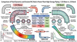
流體進入彎管受離心力驅使,外彎側壓力升高,內彎側壓力降低。在傳統的 1.5D 彎頭中,急促的 90 度轉向在內彎側產生極強的軸向逆壓梯度,導致流體動能耗散並脫離管壁,形成嚴重的流動分離。同時,強大的橫向壓力差驅使邊界層流體由外向內回流,形成極度強烈的一對反向旋轉渦核——狄恩渦流(Dean Vortices)。這猶如無形的攪拌機,持續破壞外彎側邊界層的穩定性。 As fluid enters a bend, driven by centrifugal force, pressure increases on the extrados and decreases on the intrados. In traditional 1.5D elbows, the abrupt 90-degree turn generates extremely strong axial adverse pressure gradients on the intrados, causing fluid kinetic energy to dissipate and detach from the pipe wall, forming severe flow separation. Simultaneously, the powerful transverse pressure difference drives boundary layer fluids to flow back from the outside in, forming an intensely strong pair of counter-rotating vortex cores—Dean Vortices. This acts like an invisible mixer, continuously disrupting the stability of the boundary layer on the extrados.
相反地,當採用 5D 彎管時,流體轉向過程被大幅拉長,離心力施加平緩。這有效削弱了逆壓梯度,徹底抑制了流動分離現象25;同時,生成的狄恩渦流強度極度微弱且結構鬆散。這直接提升了輸送效率,5D 彎管的總體壓力降與損失係數均顯著低於 1.5D 彎頭25。 Conversely, when 5D bends are used, the fluid turning process is significantly elongated, and centrifugal force is applied smoothly. This effectively weakens adverse pressure gradients and completely suppresses flow separation25; meanwhile, the generated Dean vortices are extremely weak in intensity and loose in structure. This directly enhances conveying efficiency, with the overall pressure drop and loss coefficients of 5D bends being significantly lower than those of 1.5D elbows25.
5.2 局部質傳係數 (MTC) 峰值削弱與下游衰減 /5.2 Peak Attenuation and Downstream Decay of Local Mass Transfer Coefficient (MTC)
數值結果顯示,在 1.5D 彎頭中,強烈的二次流將導致外彎側(約 45° 至 75°)出現極端集中的 MTC 峰值(熱點)。在此高 FAC 風險區,管壁極易發生局部穿孔15。若替換為 5D 彎管,MTC 峰值會出現顯著的「衰減」與「擴張」。峰值絕對數值通常下降 30%~50%,且危險區域沿較長的外彎側均勻分佈,達成「削峰填谷」的緩衝效應25。 Numerical results reveal that in 1.5D elbows, strong secondary flows cause extremely concentrated MTC peaks (hotspots) to appear on the extrados (around 45° to 75°). In this high FAC risk zone, pipe walls are highly prone to local perforation15. If replaced with 5D bends, MTC peaks experience significant “attenuation” and “broadening.” The absolute values of peaks typically drop by 30% to 50%, and the hazardous areas are evenly distributed along the longer extrados arc, achieving a buffering effect of “peak shaving and valley filling”25.
此外,1.5D 彎頭強烈的尾流擾動向下游直管延伸極長,通常需 5D 至 10D 的距離才能耗散恢復7。若空間受限導致兩個彎頭間距過短(如< 3D),將產生毀滅性的幾何因子疊加干涉6。5D 彎管則因出口流場畸變甚微,能以極短距離恢復穩定,賦予管線佈局極大的安全裕度與彈性33。 Additionally, the intense wake disturbances of 1.5D elbows extend very far into downstream straight pipes, typically requiring a distance of 5D to 10D to dissipate and recover7. If spatial limitations result in excessively short distances between two elbows (e.g., < 3D), devastating superimposition interference of geometric factors will occur6. In contrast, 5D bends exhibit minimal flow field distortion at the outlet, recovering stability over a very short distance, granting tremendous safety margins and flexibility to piping layouts33.
六、 工程設計最佳化指引與非破壞檢測 (NDE) 策略 /6. Engineering Design Optimization Guidelines and Non-Destructive Examination (NDE) Strategies
將前述純流體力學的流場與質傳分析轉化為實務應用後,工程界即可透過調整幾何特徵與檢測計畫,有效阻斷 FAC 的劣化途徑,將理論預測轉化為現場的維護價值。 After translating the aforementioned pure fluid mechanical flow field and mass transfer analyses into practical applications, the engineering community can effectively block FAC degradation pathways by adjusting geometric characteristics and inspection plans, turning theoretical predictions into on-site maintenance value.
6.1 檢測策略最佳化:基於 EPRI NSAC-202L 的 UT 網格規劃 /6.1 Optimization of Inspection Strategies: UT Grid Planning Based on EPRI NSAC-202L
針對易受 FAC 影響的管線,國際廣泛遵循 EPRI NSAC-202L 檢測指引執行超音波測厚(UT)2。依據本研究的流場衰減分析,UT 網格(Grid Layout)的佈置必須根據彎管曲率動態調整。對於 1.5D 彎頭,由於下游擾動傳遞極遠,測厚網格絕對不可僅標記於彎頭本體,必須向下游直管段延伸至少 2D 至 5D,以涵蓋尾流引發的薄化區2。而對於 5D 彎管,雖下游擾動短暫,但磨耗分佈較為均勻擴散,因此檢測重心應轉向對彎管本體外彎側全弧段進行無死角的全面掃描。 For pipelines susceptible to FAC, it is internationally prevalent to follow the EPRI NSAC-202L inspection guidelines for performing Ultrasonic Testing (UT)2. According to the flow field decay analysis in this study, the layout of the UT grid must be dynamically adjusted based on the bend curvature. For 1.5D elbows, because downstream disturbances propagate extensively, thickness measurement grids absolutely must not be marked solely on the elbow body; they must extend down the downstream straight pipe section for at least 2D to 5D to encompass wake-induced thinning zones2. For 5D bends, although downstream disturbances are brief, wear distribution is more uniform and dispersed. Thus, inspection focus should shift toward comprehensive, blind-spot-free scanning of the entire extrados arc segment of the bend body.
6.2 流場與材質雙重屏障設計 /6.2 Dual Barrier Design of Flow Field and Material
5D 彎管在流體力學上可延長管段壽命 1.5 至 2 倍,並降低了 ASME B31.1 規範中的應力強化因子(SIF)5。但在實務防護上,應採取「降低質傳驅動力(5D彎徑)」與「提升化學抗性(高鉻鋼材)」的雙重策略。研究表明,碳鋼中微量鉻含量若超過 0.1%,保護膜穩定性將斷崖式提升34。流場改善降低驅動力,搭配合適材質(如 P11, P22, P91 等高強度合金或不銹鋼),方可一勞永逸地根除 FAC 威脅。 Mechanically, 5D bends can extend pipe segment lifespan by 1.5 to 2 times and reduce the Stress Intensification Factor (SIF) under ASME B31.1 codes5. However, in practical protection, a dual strategy of “lowering mass transfer driving forces (5D bends)” and “enhancing chemical resistance (high-chromium steels)” should be adopted. Studies indicate that if trace chromium content in carbon steel exceeds 0.1%, protective film stability improves precipitously34. Improving the flow field to lower driving forces, coupled with appropriate materials (such as high-strength alloys like P11, P22, P91, or stainless steel), is the only way to eradicate FAC threats once and for all.
七、 CCPP P91/P92 小管徑管線系統 5D 彎徑設計下之實務效益與建廠理念 /7. Practical Benefits and Construction Concepts of 5D Bend Design for CCPP P91/P92 Small Bore Piping Systems
前述流場與檢測的分析確立了 5D 彎管在減緩流體加速腐蝕上的卓越價值;然而,在現代發電技術中,管線不僅面臨流體侵蝕,更承受著嚴苛的高溫結構應力。本節特別針對複循環電廠(Combined Cycle Power Plant, CCPP)中,極高溫、高壓且材質極其敏感的 P91/P92 小管徑管線系統,深度擴充 1.5D 與 5D 彎管在固體力學、冶金防護、空間佈局,以及 EPC 設計單位的綜合商業決策分析。 The preceding analyses of flow fields and inspection established the exceptional value of 5D bends in mitigating flow-accelerated corrosion. Yet, in modern power generation technologies, piping faces not only fluid erosion but also severe high-temperature structural stresses. This section specifically targets P91/P92 small bore piping systems—experiencing extremely high temperatures, high pressures, and highly sensitive materials—in Combined Cycle Power Plants (CCPP), deeply expanding on practical evaluations of 1.5D vs. 5D bends regarding solid mechanics, metallurgical protection, spatial layouts, and comprehensive commercial decision analysis for EPC design units.
7.1 複循環電廠 (CCPP) 之潛變與疲勞耦合挑戰 /7.1 Creep-Fatigue Coupling Challenges in Combined Cycle Power Plants (CCPP)
隨著乾淨能源與再生能源佔比的不斷擴大,現代 CCPP 多被調度作為負載跟隨(Load-following)機組。頻繁的起停循環與急劇的升降載,導致管線在極端高溫下必須反覆承受劇烈的熱膨脹循環,同時伴隨著空間佈局帶來的彎曲與扭轉疊加力矩35。這使得管線的劣化機制由單純的材料潛變(Creep),演變為高度複雜的潛變-疲勞交互作用(Creep-Fatigue Interaction)。 With the increasing share of clean and renewable energy, modern CCPPs are often dispatched as load-following units. Frequent start-stop cycles and rapid ramping mean that piping must repeatedly endure severe thermal expansion cycles under extreme temperatures, accompanied by superimposing bending and torsional moments induced by spatial layouts35. This transitions the piping degradation mechanism from simple material creep to a highly complex creep-fatigue interaction.
在標稱管徑 8 吋以下的小管徑(Small Bore Piping)系統中,傳統工法為改變流向,多採用 1.5D 鍛造彎頭並於兩端進行銲接。然而,P91/P92(P-No. 15E)這類高強度麻田散鐵耐熱鋼的機械性質,極度依賴於精確的微觀析出物分佈。銲接過程產生的熱循環,無可避免地會在母材旁形成細晶熱影響區(FGHAZ)。此一狹窄帶的潛變強度顯著低於周圍金屬,成為整體管線的弱點。在長期潛變與疲勞交替作用下,應力在此軟化帶高度集中,極易聚集成微裂紋,最終誘發無預警的第四型潛變破裂(Type IV Creep Failure)35。 In small bore piping systems under 8-inch nominal pipe sizes, traditional methods for changing flow direction usually employ 1.5D forged elbows welded at both ends. However, the mechanical properties of high-strength martensitic heat-resistant steels like P91/P92 (P-No. 15E) depend heavily on precise microscopic precipitate distributions. The thermal cycling generated by welding inevitably forms fine-grained heat-affected zones (FGHAZ) adjacent to the base metal. The creep strength of this narrow band is significantly lower than surrounding metals, making it a weak link in the overall piping. Under the alternating action of long-term creep and fatigue, stresses highly concentrate in this softened band, easily nucleating micro-cavities that coalesce into micro-cracks, ultimately inducing unpredicted Type IV creep failures35.
7.2 以彎代銲:5D 冷作彎管與 ASME B31J 規範效益 /7.2 Bending Instead of Welding: 5D Cold Bending and ASME B31J Code Benefits
為徹底根除 HAZ 導致的弱點,針對小管徑 P91/P92 管線導入 5D 數控冷作彎管工法,可實現高價值的「以彎代銲」策略36。這意味著在流向改變的關鍵高應力樞紐,完全排除了環向銲縫,從幾何與冶金源頭拔除了第四型潛變破裂的隱患。 To completely eradicate weaknesses caused by HAZ, introducing 5D CNC cold bending processes for small bore P91/P92 piping realizes a high-value “bending instead of welding” strategy36. This means that at the critical high-stress hubs where flow direction changes, circumferential welds are entirely eliminated, uprooting the hidden dangers of Type IV creep failure from their geometric and metallurgical sources.
在結構應力分析法規方面,最新版 ASME B31J 規範終結了過去高度簡化的單一應力計算模式,將應力強度因子(SIF)與持續應力指數(SSI)在物理機制上徹底解耦。5D 大曲率彎管憑藉其平緩的幾何過渡,大幅消弭了應力集中現象。其在面內(In-Plane)、面外(Out-of-Plane)及扭轉(Torsion)方向上的 SIF 值均遠低於傳統的 1.5D 銲接彎頭5。這在實務設計上為統包商與業主爭取到了極大的熱疲勞物理安全餘裕。 Regarding structural stress analysis codes, the latest ASME B31J standard ends the highly simplified single-stress calculation models of the past, completely decoupling the Stress Intensification Factor (SIF) and Sustained Stress Index (SSI) mechanically. Utilizing its gradual geometric transition, 5D large-curvature bends drastically eliminate stress concentration phenomena. Their SIF values in in-plane, out-of-plane, and torsional directions are all far lower than those of traditional 1.5D welded elbows5. In practical design, this secures tremendous physical safety margins for thermal fatigue for both contractors and owners.
7.3 應變誘發析出硬化 (SIPH) 與 PBHT 熱處理極限值 /7.3 Strain-Induced Precipitation Hardening (SIPH) and PBHT Heat Treatment Limits
儘管 5D 冷作彎管在流體力學(抑制 FAC)與固體力學(降低 SIF、免除銲道)上具有壓倒性優勢,但 P91/P92 鋼材對冷作塑性變形極度敏感。冷彎過程會引發材料內部的應變誘發析出硬化(Strain-Induced Precipitation Hardening, SIPH),導致差排大量增殖、晶界弱化與宏觀延展性驟降36。因此,冷作彎管成型後,必須對彎管段實施極度精密的亞臨界彎後熱處理(Post-Bend Heat Treatment, PBHT)38。 Although 5D cold bends possess overwhelming advantages in fluid mechanics (mitigating FAC) and solid mechanics (lowering SIF, eliminating welds), P91/P92 steels are extremely sensitive to cold plastic deformation. Cold bending processes trigger Strain-Induced Precipitation Hardening (SIPH) internally, leading to massive dislocation multiplication, grain boundary weakening, and a precipitous drop in macroscopic ductility36. Therefore, after cold bend forming, extremely precise sub-critical Post-Bend Heat Treatment (PBHT) must be implemented on the bend segments38.
實務作業上,PBHT 的參數設定必須在「消除應力」與「避免相變」之間取得平衡。熱處理溫度被最佳化鎖定於 760°C,此恆溫階段能提供足夠的熱活化能,驅動差排消散並讓碳氮化物重新彌散分佈36。更關鍵的是,此溫度嚴格守住了不跨越材料 AC1 下臨界相變溫度(極限值可能降至 785°C 以下)的安全紅線。一旦跨越AC1 極限值,材料將發生部分奧斯田鐵化,冷卻後轉變為極脆的未回火麻田散鐵,導致衝擊韌性喪失殆盡。精確控溫在 760°C 的 PBHT,能確保 P91/P92 管線在具備 5D 彎管幾何優勢的同時,完美恢復其抵抗高溫潛變的冶金韌性。 In practical operations, PBHT parameter settings must strike a balance between “stress relief” and “avoiding phase transformation.” The heat treatment temperature is optimally locked at 760°C; this isothermal phase provides sufficient thermal activation energy to drive dislocation dissipation and redistribute carbonitrides36. More crucially, this temperature strictly maintains the safety redline of not crossing the material’s AC1 lower critical phase transformation temperature (the limit may drop below 785°C). Once the AC1 limit is breached, the material will undergo partial austenitization, transforming upon cooling into highly brittle untempered martensite, resulting in a total loss of impact toughness. Precise temperature control at 760°C during PBHT ensures that while P91/P92 piping holds the geometric advantages of 5D bends, its metallurgical toughness to resist high-temperature creep is perfectly restored.
7.4 廠房內場域限制下 1.5D 與 5D 彎徑之空間設計與佈局評估 /7.4 Spatial Design and Layout Evaluation of 1.5D and 5D Bends Under Indoor Plant Space Constraints
在現代 CCPP 工廠佈局中,由於多數採用立體化與高密度的設備配置,使得廠房內保留給管線佈設的物理空間往往極度受限。傳統的直觀工程觀念多認為,為了節省當下局部的轉向空間,應盡量採用短半徑的 1.5D 銲接彎頭。然而,這種考量僅侷限於單一管件的幾何尺寸,若從系統整體流場復原與熱力學補償的角度進行評估,反而會導致整體空間規劃的惡化。 In modern CCPP plant layouts, due to the widespread use of three-dimensional and high-density equipment configurations, physical space reserved for piping layout indoors is often severely constrained. Traditional intuitive engineering concepts often hold that, to save immediate local turning space, short-radius 1.5D welded elbows should be used as much as possible. However, this consideration is limited only to the geometric dimensions of a single fitting. Evaluated from the perspective of system-wide flow field recovery and thermodynamic compensation, it actually leads to deterioration in overall space planning.
首先,就流體擾動與雙彎管干涉而言,誠如前文分析,1.5D 彎頭會產生強烈的尾流擾動,若在狹小空間內被迫連續佈置雙彎頭,將會引發極具破壞性的幾何擾動疊加干涉。相較之下,5D 彎管因自身產生的二次流與擾動極微弱,流場能在極短距離內衰減與復原,這賦予了在空間受限區密集配置連續彎管而不會引發疊加 FAC 的極大安全性。 First, regarding fluid disturbances and dual-bend interference, as previously analyzed, 1.5D elbows generate intense wake disturbances. If forced to arrange dual elbows consecutively in tight spaces, highly destructive superimposition interference of geometric disturbances will be triggered. In contrast, because 5D bends produce extremely weak secondary flows and disturbances natively, their flow fields decay and recover within very short distances. This endows immense safety for densely configuring continuous bends in constrained spaces without triggering superimposed FAC.
更關鍵的突破在於結構熱膨脹的空間補償。CCPP 的高溫管線在機組起停之間會產生龐大的熱膨脹位移量。1.5D 彎頭由於幾何僵硬,往往需要向外延伸大量的膨脹環(Expansion Loops),或是依賴佔用空間的機械式彈簧管架來強行吸收位移。相反地,5D 大半徑冷作彎管憑藉其平緩順暢的幾何特性,能夠透過管線本身的物理延展性自發性地吸收熱膨脹位移。實務評估表明,採用 5D 彎管不僅簡化了周邊組件,更可有效降低廠房內部管架整體的空間需求達 15% 至 20%。 A more critical breakthrough lies in spatial compensation for structural thermal expansion. High-temperature piping in CCPPs generates massive thermal expansion displacements between unit startups and shutdowns. Due to geometric rigidity, 1.5D elbows often require extensive outward extensions of Expansion Loops, or reliance on space-consuming mechanical spring pipe supports to forcibly absorb displacement. Conversely, relying on their gradual and smooth geometric traits, 5D large-radius cold bends can spontaneously absorb thermal expansion displacements through the physical ductility of the piping itself. Practical evaluations demonstrate that using 5D bends not only simplifies peripheral components but also effectively reduces the overall space requirements for indoor pipe racks by 15% to 20%.
7.5 廠房外管架區域 1.5D 與 5D 彎徑設計與結構支撐分析 /7.5 Design and Structural Support Analysis of 1.5D and 5D Bends in Outdoor Pipe Rack Areas
相對於廠房內部的極端空間擠壓,CCPP 廠房外部的管架區域(Pipe Racks 或 Pipe Bridges)面臨著截然不同的工程挑戰。廠外管架通常負責連接不同主設備(如鍋爐、汽機房與冷卻塔)的長距離管線輸送。對於 P91/P92 等高溫主蒸汽管線而言,長距離直管段在極端溫差下累積的熱膨脹絕對位移量極為驚人。 Compared to the extreme spatial squeezing indoors, outdoor pipe rack areas (Pipe Racks or Pipe Bridges) of CCPPs face starkly different engineering challenges. Outdoor pipe racks are usually responsible for long-distance piping conveyance connecting various main equipment (such as boilers, turbine halls, and cooling towers). For high-temperature main steam piping like P91/P92, the absolute thermal expansion displacement accumulated by long-distance straight pipe sections under extreme temperature differentials is staggeringly huge.
傳統上,為了吸收熱位移,工程師必須在管架上每隔一段距離設置由多個 1.5D 銲接彎頭組成的巨大 U 型膨脹環。然而,1.5D 彎頭極高的剛性與 SIF,使得管線在膨脹過渡區極易產生過大的扭轉應力。這迫使設計端必須在外部鋼構上大量增設昂貴且沉重的滑動支撐、限位器與彈簧吊架。這些複雜的支撐構件長期暴露於戶外環境中,其檢修與維護成本居高不下。 Traditionally, to absorb thermal displacement, engineers had to install massive U-shaped expansion loops composed of multiple 1.5D welded elbows at regular intervals along pipe racks. However, the extremely high rigidity and SIF of 1.5D elbows cause the piping to easily generate excessive torsional stress in expansion transition zones. This forces designers to extensively add expensive and heavy sliding supports, guides, and spring hangers to external steel structures. These complex support components are exposed to outdoor environments long-term, keeping inspection and maintenance costs persistently high.
導入 5D 大半徑冷作彎管,則為廠外管架佈局帶來革命性的優化。基於 ASME B31J 的彈性分析,5D 彎管能以極低的應力代價,如同彈簧般平順且自發性地吸收來自長直管的熱位移。這種「以彎代銲、以柔克剛」的設計思維,將傳遞至鋼結構上的端點反力與力矩降至最低,使得廠外管架主體得以大幅輕量化,降低整體管架結構材料與建造空間需求 15% 至 20%。 Introducing 5D large-radius cold bends brings revolutionary optimization to outdoor pipe rack layouts. Based on ASME B31J flexibility analysis, 5D bends can smoothly and spontaneously absorb thermal displacement from long straight pipes like a spring at an extremely low stress cost. This design philosophy of “bending instead of welding, using softness to conquer hardness” minimizes the terminal reaction forces and moments transmitted to steel structures. This enables substantial light-weighting of outdoor pipe rack main bodies, lowering overall rack structural material and construction space demands by 15% to 20%.
7.6 EPC 承包商設計單位之 1.5D 與 5D 彎徑抉擇與建廠設計理念 /7.6 1.5D and 5D Bend Selections and Construction Design Concepts by EPC Contractor Design Units
在大型 CCPP 的建廠專案中,統包商(EPC, Engineering, Procurement, and Construction)的設計單位不僅需確保管線系統的可靠度,更面臨嚴苛的建廠時程與成本控制壓力。對於極為敏感的高價 P91/P92 高能管線,選擇 1.5D 銲接彎頭或 5D 冷作彎管,反映了截然不同的商業決策與工程設計理念。 In large-scale CCPP construction projects, the design units of EPC (Engineering, Procurement, and Construction) contractors must not only ensure the reliability of piping systems but also face severe pressures regarding construction schedules and cost control. For highly sensitive, high-priced P91/P92 high-energy piping, choosing 1.5D welded elbows versus 5D cold bends reflects starkly different commercial decisions and engineering design philosophies.
傳統上,EPC 設計單位傾向採用 1.5D 鍛造彎頭,主要著眼於其作為標準化管件的易取得性。然而,隨著 ASME B31J 規範的導入,應力分析工程師遭遇了強烈的「應力分析衝擊(Stress Analysis Shock)」。B31J 嚴格解耦了 SIF 與 SSI,1.5D 彎頭在面對複雜的廠區熱膨脹時,其極高的 SIF 值經常導致管線應力超標。為解決應力熱點,EPC 被迫投入大量工時進行佈局修改,並在現場增設昂貴的支撐構件,這不僅抵銷了彎頭本身的初始成本優勢,更拖延了設計進度。 Traditionally, EPC design units tend to adopt 1.5D forged elbows, primarily eyeing their easy availability as standardized fittings. However, with the introduction of the ASME B31J code, stress analysis engineers encountered severe “Stress Analysis Shock”. B31J strictly decoupled SIF and SSI; when facing complex plant thermal expansions, the extremely high SIF values of 1.5D elbows frequently cause piping stress to exceed allowable limits. To resolve stress hotspots, EPCs are forced to invest massive man-hours in modifying layouts and adding expensive support components on-site. This not only offsets the initial cost advantage of the elbows themselves but also delays design schedules.
相對於傳統作法,具備前瞻性的 EPC 設計單位逐漸將 5D 數控冷作彎管視為創造「商業利基」的核心策略。在建廠設計理念上,導入 5D 彎管體現了「預製整合」與「以彎代銲」的雙重價值。在執行實務面上,將零散的 1.5D 彎頭與直管整合為單一 5D 大型預製管段(Prefabricated Spools),直接消除了大量的現場環向銲縫。這大幅減少了高階銲工的現場需求與耗時的高溫銲後熱處理(PWHT),同時免除了昂貴的非破壞檢驗(如射線探傷 RT 或超音波檢測 UT)工序與潛在的返修風險。 Compared to traditional methods, forward-looking EPC design units increasingly view 5D CNC cold bends as a core strategy for creating a “commercial niche”. In construction design philosophies, introducing 5D bends embodies the dual values of “prefabrication integration” and “bending instead of welding.” On the practical execution front, integrating scattered 1.5D elbows and straight pipes into single 5D large prefabricated spools directly eliminates voluminous on-site circumferential welds. This drastically reduces the on-site demand for high-level welders and time-consuming high-temperature Post-Weld Heat Treatment (PWHT), while eliminating expensive non-destructive examination (such as radiographic testing RT or ultrasonic testing UT) procedures and potential rework risks.
最終,EPC 設計單位選擇 5D 彎管,是將微觀的材料科學(避免熱影響區)、中觀的結構力學(降低 SIF,吸收熱位移)轉化為宏觀的專案管理效益。透過減少高空施銲、簡化供應鏈物料管理,並降低管架鋼構噸數,5D 彎管的設計理念不僅為業主交付了更安全、壽命更長的電廠,更實質提升了 EPC 統包商在激烈市場中的工程競爭力與獲利空間。 Ultimately, EPC design units choosing 5D bends translates microscopic material science (avoiding heat-affected zones) and mesoscopic structural mechanics (lowering SIF, absorbing thermal displacement) into macroscopic project management benefits. By reducing high-altitude welding, simplifying supply chain materials management, and lowering the tonnage of pipe rack steel structures, the 5D bend design philosophy not only delivers safer, longer-lasting power plants for owners but also substantively elevates the engineering competitiveness and profit margins of EPC contractors in a fierce market.
八、 結論 / 8. Conclusion
本研究透過嚴謹的理論溯源與高解析度數值分析,深度剖析了電廠高能管線中 1.5D 與 5D 彎管對流場演化、擾動傳遞及流體加速腐蝕(FAC)風險的影響;並進一步將視角擴展至結構應力、冶金防護,以及貫穿建廠實務的 EPC 商業設計理念,為工程實務提供科學化的量化指引。總結核心發現與結論如下:Through rigorous theoretical tracing and high-resolution numerical analysis, this study deeply dissected the impacts of 1.5D vs. 5D bends in power plant high-energy piping on flow field evolution, disturbance propagation, and Flow-Accelerated Corrosion (FAC) risks. It further expanded the perspective to structural stress, metallurgical protection, and EPC commercial design philosophies that permeate construction practices, providing scientific quantitative guidelines for engineering applications. Core findings and conclusions are summarized as follows:
- FAC 預測高度依賴質傳分析,WSS 不具備獨佔指標性:FAC 是由質量傳遞主導的電化學劣化過程。在極端水化學環境中,數值模擬必須具備精細的近壁面網格解析度(y+ ≦ 1)以捕捉微觀濃度邊界層。在複雜彎管中,傳統仰賴壁面剪應力(WSS)的評估方式會因流動分離區的動量-質量解耦而導致嚴重誤判10。FAC Prediction Highly Relies on Mass Transfer Analysis; WSS Lacks Exclusive Indicator Value: FAC is an electrochemical degradation process dominated by mass transfer. In extreme water chemistry environments, numerical simulations must possess fine near-wall mesh resolution (y+ ≦ 1) to capture the micro-concentration boundary layer. In complex bends, traditional assessment methods relying on Wall Shear Stress (WSS) lead to severe misjudgments due to momentum-mass decoupling in flow separation zones10.
- 1.5D 銲接彎頭具備極高的流場破壞性與 FAC 風險:短半徑彎頭因急促轉向產生強烈逆壓梯度與狄恩渦流。這導致彎管外側出現極端集中的 MTC 峰值,其伴隨的尾流擾動更會向下游延伸 5D 至 10D 以上,形成大範圍的高 FAC 暴露區6。1.5D Welded Elbows Possess High Flow Field Destructiveness and FAC Risks: Short-radius elbows generate strong adverse pressure gradients and Dean vortices due to abrupt turning. This causes extremely concentrated MTC peaks on the bend’s extrados, and accompanied wake disturbances can extend downstream for over 5D to 10D, creating large areas of high FAC exposure6.
- 5D 彎管展現卓越的流場穩定與延壽效益:擴大曲率半徑至 5D 可顯著削弱二次流強度與壓力降。5D 彎管內的流體衝擊極為平緩,MTC 峰值大幅降低並呈均勻擴散(削峰填谷),有效消弭了局部穿孔的危機,同時阻斷了異常擾動向下游連續組件的危險疊加25。5D Bends Exhibit Outstanding Flow Field Stability and Life-Extension Benefits: Enlarging curvature radius to 5D significantly weakens secondary flow intensity and pressure drop. Fluid impacts inside 5D bends are extremely gentle, and MTC peaks are drastically lowered and spread evenly (peak shaving), effectively neutralizing local perforation crises and simultaneously blocking the hazardous superimposition of abnormal disturbances onto continuous downstream components25.
- 工程檢測與防護策略之實務革新:執行基於 EPRI NSAC-202L 的超音波測厚計畫時,必須針對1.5D 彎頭落實下游直管的延伸檢測以捕捉尾流薄化2。整體防護建議結合 5D 彎徑的幾何最佳化與高鉻鋼材的冶金升級,以雙管齊下達成安全運轉。Practical Innovation of Engineering Inspection and Protection Strategies: When executing Ultrasonic Testing programs based on EPRI NSAC-202L, extended inspection of downstream straight pipes must be implemented for 1.5D elbows to capture wake-induced thinning2. Overall protection is recommended to combine geometric optimization via 5D bend radii with metallurgical upgrades using high-chromium steels, achieving safe operations via a two-pronged approach.
- 解決 P91/P92 潛變疲勞與提升 EPC 建廠競爭力的最佳方案:在頻繁起停的複循環電廠中,將1.5D 銲接彎頭汰換為 5D 冷作彎管,可實現「以彎代銲」,徹底消滅易引發第四型潛變破裂的熱影響區(HAZ)。在滿足 ASME B31J 極低應力強度因子的優勢下,嚴格控制 760°C 熱處理以不逾越 Ac1 極限值,可完美恢復材料韌性。更重要的是,從 EPC 統包商的設計理念出發,5D 彎管優異的延展性能自發吸收室內外管架的熱膨脹位移,減少管架鋼構需求,並透過大型預製管段大幅降低現場高空施銲、檢測與熱處理的成本與風險。這證實了 5D 彎管能完美兼顧流體防腐蝕、固體抗疲勞與整體專案獲利的三重實務效益。Optimal Solution to Resolve P91/P92 Creep-Fatigue and Elevate EPC Construction Competitiveness: In frequently cycling CCPPs, replacing 1.5D welded elbows with 5D cold bends realizes “bending instead of welding,” completely eradicating heat-affected zones (HAZ) prone to inducing Type IV creep ruptures. While leveraging the extremely low Stress Intensification Factors under ASME B31J, strict 760°C heat treatment controlled to not exceed Ac1 limits perfectly restores material toughness. More importantly, from the design philosophy of EPC contractors, the excellent ductility of 5D bends spontaneously absorbs thermal expansion displacements of indoor and outdoor pipe racks, reduces steel structure demands for racks, and drastically cuts on-site high-altitude welding, inspection, and heat treatment costs and risks through large prefabricated spools. This verifies that 5D bends can perfectly balance the triple practical benefits of fluid anti-corrosion, solid anti-fatigue, and overall project profitability.
參考文獻/ References
- DEVELOPMENT OF ON-LINE MONITORING SYSTEM FOR FLOW, https://repository.lib.ncsu.edu/bitstreams/87ae06be-5509-4642-abb9-47a03a4d2ce1/download
- Recommendations for an Effective Flow-Accelerated Corrosion, https://restservice.epri.com/publicdownload/000000003002000563/0/Product
- Determination of High-Risk Zones for Local Wall Thinning due to, https://www.jsm.or.jp/ejam/Vol.5No.2/AA/SP9/AA61/AA61.pdf
- 針對CCPP汽水兩相流管路中5D至5D彎管曲率半徑優化配置與抗沖, https://yz-pipe-bending.com.tw/%E9%87%9D%E5%B0%8Dccpp%E6%B1%BD%E6%B0%B4%E5%85%A9%E7%9B%B8%E6%B5%81%E7%AE%A1%E8%B7%AF%E4%B8%AD1-5d%E8%87%B35d%E5%BD%8E%E7%AE%A1%E6%9B%B2%E7%8E%87%E5%8D%8A%E5%BE%91%E5%84%AA%E5%8C%96%E9%85%8D%E7%BD%AE/
- 2026 ASME 規範下1 動力管線施工工法之深度剖析, https://yz-pipe-bending.com.tw/2026-asme-%E8%A6%8F%E7%AF%84%E4%B8%8B-b31-1-%E5%8B%95%E5%8A%9B%E7%AE%A1%E7%B7%9A%E6%96%BD%E5%B7%A5%E5%B7%A5%E6%B3%95%E4%B9%8B%E6%B7%B1%E5%BA%A6%E5%89%96%E6%9E%90%EF%BC%9A5d-%E5%86%B7%E4%BD%9C%E5%BD%8E/
- (PDF) Prediction of flow-accelerated corrosion in single/dual elbow, https://www.researchgate.net/publication/372391715_Prediction_of_flow-accelerated_corrosion_in_singledual_elbow_in_pipelines_considering_geometric_parameters_and_layout_effect
- CFD Prediction of The Effects of The Upstream Elbow Fittings On, https://www.scribd.com/document/502291002/CFD-prediction-of-the-effects-of-the-upstream-elbow-fittings-on-the-performance-of-CFM
- 基於ASME B31.3 規範之高黏度流體輸送管線研究:5D CNC 冷作彎, https://yz-pipe-bending.com.tw/%E5%9F%BA%E6%96%BC-asme-b31-3-%E8%A6%8F%E7%AF%84%E4%B9%8B%E9%AB%98%E9%BB%8F%E5%BA%A6%E6%B5%81%E9%AB%94%E8%BC%B8%E9%80%81%E7%AE%A1%E7%B7%9A%E7%A0%94%E7%A9%B6%EF%BC%9A5d-cnc-%E5%86%B7%E4%BD%9C%E5%BD%8E/
- FLOW-ACCELERATED CORROSION IN NUCLEAR POWER PLANTS, https://www.osti.gov/etdeweb/servlets/purl/671638
- A direct measurement of wall shear stress in multiphase flow—Is it, https://www.icmt.ohio.edu/documents/Journals2016/A%20direct%20measurement%20of%20wall%20shear%20stress%20in%20multiphase%20flow.pdf
- Using X-Ray portable fluorescence for alloy contents measurement, https://inis.iaea.org/records/mwp52-qt159/files/46071890.pdf
- Mechanisms of Flow Accelerated Corrosion in CANDU Feeder Piping, https://www.kns.org/files/pre_paper/29/99S-229.pdf
- Predictive Modelling of Flow-accelerated Corrosion – ResearchGate, https://www.researchgate.net/publication/288609129_Predictive_Modelling_of_Flow-accelerated_Corrosion_-_Unresolved_Problems_and_Issues
- High-Confidence Flow Accelerated Corrosion Screening Technique, https://www.kns.org/files/pre_paper/12/474%EB%A5%98%EA%B2%BD%ED%95%98.pdf
- The Role of Flow in Flow-Accelerated Corrosion under Nuclear, https://www.jsm.or.jp/ejam/Vol.4No.2/AA/SP6/AA41.pdf
- Thinned Pipe Management Program of Korean NPPs, https://repository.lib.ncsu.edu/bitstreams/8ab9237d-84d2-4c52-a31e-8cd6c56994a2/download
- THINNED PIPE MANAGEMENT PROGRAM OF KOREAN, https://www.j-cst.org/main/download.htm?code=C00140100001
- parameters influencing flow-accelerated corrosion (fac) in the, https://www.collectionscanada.gc.ca/obj/thesescanada/vol2/002/NR82765.PDF
- Erosion/Corrosion in Power Plants Single- and Two-Phase Flow, https://repository.lib.ncsu.edu/bitstreams/2118c6a5-f19e-4890-85a0-c11129f32118/download
- Relationship Between Wall Shear Stress Maximum Shear Stress, https://resources.system-analysis.cadence.com/blog/msa2022-the-relationship-between-wall-shear-stress-and-the-maximum-shear-stress-formula
- Correlation between Flow Accelerated Corrosion and Wall Shear, https://www.researchgate.net/publication/269756729_Correlation_between_Flow_Accelerated_Corrosion_and_Wall_Shear_Stress_Downstream_from_an_Orifice
- Numerical Investigation and Optimization of the Flow Characteristics, https://psecommunity.org/wp-content/plugins/wpor/includes/file/2302/LAPSE-2023.1540-1v1.pdf
- Numerical investigation of interfacial mass transfer in two phase, https://www.tandfonline.com/doi/full/10.1080/19942060.2015.1061555
- CFD Investigation on Secondary Flow Characteristics in Double, https://www.mdpi.com/2077-1312/10/9/1264
- Experimental and CFD investigations of 45 and 90 degrees bends, https://www.researchgate.net/publication/349050501_Experimental_and_CFD_investigations_of_45_and_90_degrees_bends_and_various_elbow_curvature_radii_effects_on_solid_particle_erosion
- Non-Axisymmetric Mass Transfer Phenomenon behind an Orifice in, https://www.scirp.org/journal/paperinformation?paperid=30557
- Computational fluid dynamics analysis of a micro-scale chamber for, https://pmc.ncbi.nlm.nih.gov/articles/PMC10776009/
- Numerical simulations of mass transfer in turbulent pipe flow at high, https://www.researchgate.net/publication/366946064_Numerical_simulations_of_mass_transfer_in_turbulent_pipe_flow_at_high_schmidt_numbers
- Simulation of a High Speed Counting System for SiC Neutron Sensors, https://www.kns.org/files/pre_paper/39/18S-590%EC%86%90%EC%A7%80%ED%98%84.pdf
- Buttweld Bend vs Elbow: Key Differences Explained – JS FITTINGS, https://www.jsfittingsglobal.com/knowledge/buttweld-bend-vs-elbow-key-differences-explained
- University of Huddersfield Repository, https://eprints.hud.ac.uk/id/eprint/27889/1/Article.pdf
- Impact of solid particle geometry, size, and intensity, coupled with, https://www.researchgate.net/publication/394858152_Impact_of_solid_particle_geometry_size_and_intensity_coupled_with_fluid_velocity_on_erosion_dynamics_in_elbow_conduits
- 管線製程幾何優化分析:以彎徑5D 轉換3D 及管徑放大策略為例, https://yz-pipe-bending.com.tw/%E7%AE%A1%E7%B7%9A%E8%A3%BD%E7%A8%8B%E5%B9%BE%E4%BD%95%E5%84%AA%E5%8C%96%E5%88%86%E6%9E%90%E4%BB%A5%E5%BD%8E%E5%BE%91-1-5d-%E8%BD%89%E6%8F%9B-3d-%E5%8F%8A%E7%AE%A1%E5%BE%91%E6%94%BE%E5%A4%A7%E7%AD%96/
- Flow-Accelerated Corrosion Investigations of Trace Chromium – EPRI, https://restservice.epri.com/publicdownload/000000000001008047/0/Product
- Creep-Fatigue Life Property of P91 Welded Piping Subjected to, https://www.researchgate.net/publication/372528500_Creep-Fatigue_Life_Property_of_P91_Welded_Piping_Subjected_to_Bending_and_Torsional_Moments_at_High_Temperature
- 基於ASME B31J 規範之P91/P92 高強度合金冷作彎管工法應力解析與, https://yz-pipe-bending.com.tw/%E5%9F%BA%E6%96%BC-asme-b31j-%E8%A6%8F%E7%AF%84%E4%B9%8B-p91-p92-%E9%AB%98%E5%BC%B7%E5%BA%A6%E5%90%88%E9%87%91%E5%86%B7%E4%BD%9C%E5%BD%8E%E7%AE%A1%E5%B7%A5%E6%B3%95%E6%87%89%E5%8A%9B%E8%A7%A3%E6%9E%90/
- CCPP 8吋以下管線方向變更方案之差異化分析研究:5D電銲彎頭與, https://yz-pipe-bending.com.tw/ccpp-8%E5%90%8B%E4%BB%A5%E4%B8%8B%E7%AE%A1%E7%B7%9A%E6%96%B9%E5%90%91%E8%AE%8A%E6%9B%B4%E6%96%B9%E6%A1%88%E4%B9%8B%E5%B7%AE%E7%95%B0%E5%8C%96%E5%88%86%E6%9E%90%E7%A0%94%E7%A9%B6%EF%BC%9A1-5d%E9%9B%BB/
- Finite element simulation of welded P91 steel pipe undergoing post, https://www.researchgate.net/publication/233497204_Finite_element_simulation_of_welded_P91_steel_pipe_undergoing_post-weld_heat_treatment
- Finite element simulation of welding and residual stresses in a P91, https://www.researchgate.net/publication/245394672_Finite_element_simulation_of_welding_and_residual_stresses_in_a_P91_steel_pipe_incorporating_solid-state_phase_transformation_and_post-weld_heat_treatment