
一、 緒論 / I. Introduction
在現代化工業及城市廢水處理廠的整體運作中,高濃度汙泥的輸送管線系統是連接沉澱、濃縮、厭氧消化與最終脫水單元的核心動脈。隨著環保法規日益嚴格以及後端處置成本的攀升,當今的廢水處理技術無不致力於提升汙泥的總固體含量(Total Solids, TS),以最大幅度降低汙泥的體積與含水率。然而,當汙泥的固體濃度顯著提高時,其流體動力學特性會發生根本性的轉變,從低濃度時近似於水的牛頓流體(Newtonian fluid),轉變為具有高度複雜性的非牛頓流體(Non-Newtonian fluid),並展現出顯著的降伏應力(Yield stress)與剪切變薄(Shear-thinning)行為1。 In the overall operation of modernized industrial and municipal wastewater treatment plants, the high-concentration sludge transport pipeline system serves as the core artery connecting sedimentation, thickening, anaerobic digestion, and final dewatering units. With increasingly stringent environmental regulations and rising backend disposal costs, contemporary wastewater treatment technologies consistently strive to increase the Total Solids (TS) content of sludge, thereby maximizing the reduction of sludge volume and moisture content. However, as the solid concentration of sludge increases significantly, its fluid dynamic characteristics undergo a fundamental shift—from a Newtonian fluid resembling water at low concentrations to a highly complex Non-Newtonian fluid, exhibiting significant Yield stress and Shear-thinning behavior1.
這種流變特性的劇烈改變,為管線系統的流體力學設計帶來了前所未有的挑戰。在漫長的管路輸送過程中,流體不僅需要克服直管段的高黏性摩擦阻力,更在流經管線轉向元件(即彎管或彎頭,Bends/Elbows)時,面臨劇烈的流場畸變。由於非牛頓流體在彎管中會受到不平衡的離心力作用,引發強烈的次級流(Secondary flow,即狄恩渦 Dean vortices),這不僅導致局部壓力降(Pressure drop)非線性地急遽上升,更將高動量的固體顆粒導向彎管的特定區域,造成嚴重的局部磨耗4。 This drastic change in rheological properties presents unprecedented challenges for the fluid dynamic design of pipeline systems. During long-distance transport, the fluid must not only overcome high-viscosity frictional resistance in straight sections but also face severe flow field distortion when passing through directional components (i.e., bends or elbows). Due to unbalanced centrifugal forces acting on non-Newtonian fluids in bends, strong secondary flows (Dean vortices) are induced. This not only causes the local pressure drop to rise non-linearly and sharply but also directs high-momentum solid particles toward specific areas of the bend, resulting in severe localized erosion4.
為滿足複雜廠區的空間佈局限制,管線工程中廣泛應用冷作彎管(Cold bending)技術來成型各種角度與曲率半徑(Bend Radius,通常以管徑D的倍數表示為R值,如1.5D、3D、5D、7D等)的轉向管件8。然而,冷作加工是一種在常溫下藉由強大機械力迫使金屬管材發生塑性變形的製程。此過程不可避免地會造成管壁外弧(Extrados)減薄、內弧(Intrados)增厚,並伴隨截面橢圓度(Ovality)的增加,同時在材料內部殘留極高的拉伸應力9。 To accommodate the spatial layout constraints of complex plants, pipeline engineering widely employs cold bending techniques to form directional fittings of various angles and bend radii (typically expressed as an R-value, a multiple of the pipe diameter D, such as 1.5D, 3D, 5D, 7D, etc.)8. However, cold working is a process that forces metal pipes into plastic deformation using immense mechanical force at room temperature. This process inevitably causes wall thinning at the extrados, wall thickening at the intrados, an increase in cross-sectional ovality, and leaves extremely high residual tensile stresses within the material9.
當流體動力學層面的「次級流磨耗」與固體力學層面的「冷彎外弧減薄及殘餘應力」在彎管的外弧處重疊時,便形成了一個極高風險的多物理場耦合失效熱區。若加上廢水汙泥中常見的腐蝕性介質(如氯離子或硫化氫),極易誘發應力腐蝕開裂(Stress Corrosion Cracking, SCC),導致管線無預警穿孔或爆裂13。因此,彎管R值的選用絕非僅是幾何尺寸的決定,而是牽涉流變學、流體力學、材料力學與破壞力學的深度最佳化問題。本研究將全面解析高濃度汙泥的輸送流體機制,探討冷作彎管的力學變形特徵,並基於ASME B31.3等國際規範,提出一套具備學理基礎與實務價值的彎管R值選用準則。 When “secondary flow erosion” from fluid dynamics overlaps with “cold bend extrados thinning and residual stress” from solid mechanics at the outer arc of the bend, an extremely high-risk multi-physics coupled failure hot zone is formed. Combined with corrosive media commonly found in wastewater sludge (such as chlorides or hydrogen sulfide), this condition easily triggers Stress Corrosion Cracking (SCC), leading to unpredicted pipeline perforation or bursting13. Therefore, selecting the bend R-value is not merely a geometric decision but an in-depth optimization problem involving rheology, fluid mechanics, solid mechanics, and fracture mechanics. This study will comprehensively analyze the transport fluid mechanisms of high-concentration sludge, explore the mechanical deformation characteristics of cold bends, and propose a set of theoretically sound and practically valuable R-value selection criteria based on international standards such as ASME B31.3.
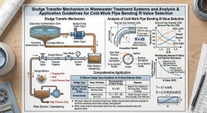
二、 高濃度汙泥之非牛頓流變學特性分析 / II. Non-Newtonian Rheological Characteristics of High-Concentration Sludge
2.1 廣義流變模型與降伏應力之物理意義 / 2.1 Generalized Rheological Models and the Physical Significance of Yield Stress
廢水處理系統中的汙泥,無論是初沉汙泥(Primary sludge)、廢水活性汙泥(Waste activated sludge, WAS)或厭氧消化汙泥(Digested sludge),其內部均含有大量的有機膠體、無機懸浮顆粒及胞外聚合物(Extracellular Polymeric Substances, EPS)。當這些複雜組分的總固體質量濃度(TS)超過約2%時,顆粒間的交互作用力(如凡得瓦力、靜電斥力及高分子鏈的空間位阻)會形成三維的絮體網絡結構,賦予汙泥顯著的非牛頓流體特徵2。 Sludge in wastewater treatment systems, whether primary sludge, waste activated sludge (WAS), or digested sludge, contains vast amounts of organic colloids, inorganic suspended particles, and extracellular polymeric substances (EPS). When the Total Solids (TS) mass concentration of these complex components exceeds approximately 2%, inter-particle interaction forces (such as van der Waals forces, electrostatic repulsion, and steric hindrance of polymer chains) form a three-dimensional floc network structure, granting the sludge significant non-Newtonian fluid characteristics2.
為了準確描述此類流體的剪切應力(Shear stress, τ)與剪切速率(Shear rate, γ ̇)之間的非線性關係,學術與工程界最廣泛採用的數學模型為Herschel-Bulkley(H-B)模型2。其一般數學表達式為: To accurately describe the non-linear relationship between the shear stress (τ) and shear rate (γ ̇ ) of such fluids, the academic and engineering communities most widely adopt the Herschel-Bulkley (H-B) model2. Its general mathematical expression is:
τ=τy+Kγ ̇ n
其中,τy 為降伏應力(Yield stress, Pa),K 為稠度指數(Consistency index, Pa·sn),n 為流動行為指數(Flow behavior index,無因次)16。 Where τy is the yield stress (Pa), K is the consistency index (Pa·sn), and n is the dimensionless flow behavior index16.
降伏應力 τy 代表了流體開始流動所需克服的最小剪切應力極限值。當管內驅動壓力所產生的壁面剪應力小於 τy 時,汙泥內部的三維絮體結構未被破壞,流體呈現類似固體的彈性變形而保持靜止;唯有當施加的應力跨越此臨界值後,絮體結構崩解,流體才開始產生連續變形與流動3。當流動開始後,若n=1,該模型退化為理想的Bingham塑性模型(Bingham plastic);若 n < 1,則流體展現出剪切變薄(Pseudoplastic, 假塑性)特徵,即表觀黏度(Apparent viscosity)隨著剪切速率的增加而降低,這是多數高濃度活性汙泥與消化汙泥的核心流變特徵3。 The yield stress τy represents the minimum shear stress threshold that must be overcome for the fluid to initiate flow. When the wall shear stress generated by the driving pressure in the pipe is less than τy, the three-dimensional floc structure within the sludge remains intact, and the fluid exhibits solid-like elastic deformation and remains stationary. Only when the applied stress crosses this critical limit does the floc structure collapse, allowing the fluid to undergo continuous deformation and flow3. Once flow begins, if n=1, the model degrades to an ideal Bingham plastic model; if n < 1, the fluid exhibits shear-thinning (pseudoplastic) behavior, meaning the apparent viscosity decreases as the shear rate increases. This is the core rheological characteristic of most high-concentration activated and digested sludges3.
2.2 總固體濃度與微觀結構對流變參數之影響 / 2.2 Effects of Total Solid Concentration and Microstructure on Rheological Parameters
汙泥的流變參數高度依賴於其總固體濃度與有機物組成。透過旋轉流變儀(Rotational rheometer)與振盪測試(Oscillatory tests)的數據顯示,隨著TS濃度的提升,降伏應力 τy 與稠度指數 K 呈現指數型或冪律型式的劇烈增長3。 The rheological parameters of sludge are highly dependent on its total solid concentration and organic composition. Data from rotational rheometers and oscillatory tests show that as TS concentration increases, the yield stress τy and consistency index K exhibit extreme exponential or power-law growth3.
以下表格彙整了不同類型與濃度之汙泥的典型Herschel-Bulkley流變參數,以彰顯濃度對流變性質的決定性影響:The following table summarizes typical Herschel-Bulkley rheological parameters for various types and concentrations of sludge to highlight the decisive impact of concentration on rheological properties:
| 汙泥種類與狀態 (Sludge Type & State) | 總固體濃度 (TS %) | 降伏應力 τy (Pa) | 稠度指數 K (Pa·sn) | 流動行為指數 n | 流體行為特徵 (Fluid Behavior Characteristics) |
| 初沉汙泥 (Primary Sludge) | ~4.0% | 0.37 | 0.66 | 0.85 | 弱降伏,輕微剪切變薄 (Weak yield, slight shear-thinning) |
| 廢水活性汙泥 (WAS/TWAS) | 3.5% – 4.0% | 2.5 – 19.4 | 0.18 – 1.2 | 0.5 – 0.7 | 顯著剪切變薄,具降伏應力 (Significant shear-thinning, possesses yield stress) |
| 消化汙泥 (Digested Sludge) | 2.0% – 5.5% | 1.5 – 25.0 | 0.2 – 2.8 | 0.4 – 0.6 | 高度剪切變薄,黏度隨濃度飆升 (Highly shear-thinning, viscosity surges with TS) |
| 高濃度混合膏體 (Dense Paste) | 10.0% – 15.0% | > 150 | > 10.0 | < 0.4 | 類固體膏狀,極高降伏應力 (Solid-like paste, extremely high yield stress) |
除了TS濃度外,汙泥中的揮發性固體(Volatile Solids, VS)比例及胞外聚合物(EPS)的含量亦扮演關鍵角色。EPS具有高度的親水性與黏性,能夠在顆粒間形成強韌的交聯結構。在振盪頻率掃描測試中,儲存模量(Storage modulus, G”)與損耗模量(Loss modulus, G”)的交會點定義了動態降伏應力與流動點(Flow point)。對於高TS含量的汙泥而言,G” 通常遠大於 G”,顯示其強烈的彈性固體特徵,這使得流體在管內的流速分佈(Velocity profile)嚴重偏離牛頓流體的拋物線,轉而形成中心為「未降伏剛性核心」(Unyielded plug core)的鈍頭柱狀塞流(Plug flow)16。 Besides TS concentration, the proportion of Volatile Solids (VS) and Extracellular Polymeric Substances (EPS) in the sludge play crucial roles. EPS is highly hydrophilic and viscous, forming robust cross-linked structures between particles. In oscillatory frequency sweep tests, the crossover point of the storage modulus (G”) and loss modulus (G”) defines the dynamic yield stress and flow point. For high-TS sludge, G” is typically much greater than G”, indicating strong elastic solid characteristics. This causes the in-pipe velocity profile to deviate severely from the parabolic curve of Newtonian fluids, forming instead a blunt-headed plug flow with an “unyielded plug core” at the center16.
三、 直管內流體動力學與管壁摩擦預測 / III. Straight Pipe Fluid Dynamics and Wall Friction Prediction
3.1 廣義非牛頓雷諾數與流態過渡 / 3.1 Generalized Non-Newtonian Reynolds Number and Flow Transition
在管線工程設計中,預測壓力降的首要步驟是評估流動狀態(層流、過渡流或亂流),這依賴於精確定義的雷諾數。對於服從Herschel-Bulkley或冪律模型的汙泥,傳統基於恆定黏度的牛頓雷諾數不再適用,必須採用廣義雷諾數。最為經典的是Metzner-Reed廣義雷諾數(ReMR),其定義旨在使非牛頓層流的范寧摩擦係數(Fanning friction factor, f)維持與牛頓流體相同的理論形式:f=16/ReMR 1。 In pipeline engineering design, the primary step in predicting pressure drop is assessing the flow regime (laminar, transitional, or turbulent), which relies on a precisely defined Reynolds number. For sludge following the Herschel-Bulkley or power-law models, the traditional Newtonian Reynolds number based on constant viscosity is no longer applicable; a generalized Reynolds number must be used. The most classic is the Metzner-Reed generalized Reynolds number (ReMR), defined to maintain the theoretical form of the Fanning friction factor (f) for non-Newtonian laminar flow identical to that of Newtonian fluids: f=16/ReMR 1.
Metzner-Reed雷諾數定義為:The Metzner-Reed Reynolds number is defined as:
ReMR=ρDn V2-n/(8n-1K'(3n+1)/4n)n
其中 D 為管徑,V 為平均流速,ρ為密度, K’ 與 n’分別為與管壁剪應力相關的表觀稠度與表觀流動指數1。 Where D is the pipe diameter, V is the average velocity, ρ is the density, and K’ and n’ are the apparent consistency and apparent flow behavior index related to the wall shear stress, respectively1.
當流動由層流轉向亂流時,汙泥內部絮體結構在強烈的剪切與微尺度渦流(Micro eddies)作用下徹底崩解。對於高降伏應力流體,亂流核心區的速度剖面仍會受到流變特性的限制。Slatter等人針對高濃度汙泥與礦漿,提出了修正的非牛頓雷諾數(如Re2 或Rer),考量了降伏應力對黏性底層(Viscous sublayer)的增厚效應。利用這些廣義雷諾數建立的複合冪律關聯式(Composite power-law correlations),能將層流至亂流全區域的壓力降預測誤差控制在 ±20% 的工程容許範圍內1。 As flow transitions from laminar to turbulent, the internal floc structure of the sludge completely collapses under intense shear and micro eddies. For high yield stress fluids, the velocity profile in the turbulent core remains restricted by rheological properties. Slatter et al. proposed modified non-Newtonian Reynolds numbers (such as Re2 or Rer) for high-concentration sludge and slurries, considering the thickening effect of yield stress on the viscous sublayer. By establishing composite power-law correlations using these generalized Reynolds numbers, pressure drop prediction errors across the entire laminar-to-turbulent regime can be controlled within an engineering tolerance of ±20% 1.
3.2 壁滑移效應 (Wall Slip Effect) 於高濃度輸送中之機制 / 3.2 Mechanisms of Wall Slip Effect in High-Concentration Transport
在高濃度緻密汙泥(如TS大於15%的脫水汙泥或電石渣漿 Calcium carbide sludge)的管線輸送中,一個極為特殊且重要的物理現象是壁滑移效應(Wall Slip Effect)22。由於管壁附近的剪切速率最高,汙泥中的固體顆粒在剪切梯度下會受到徑向遷移力(Shear-induced particle migration)的作用,被迫向管中心低剪切區域移動。這種相分離機制導致管壁周圍形成了一層極薄、主要由水分與極細微顆粒組成的低黏度潤滑層(Lubrication layer)。 In the pipeline transport of high-concentration dense sludge (such as dewatered sludge with TS > 15% or calcium carbide sludge), a highly unique and crucial physical phenomenon is the Wall Slip Effect22. Because the shear rate is highest near the pipe wall, solid particles in the sludge are subjected to radial shear-induced particle migration, forcing them toward the low-shear region at the pipe’s center. This phase separation mechanism creates an extremely thin, low-viscosity lubrication layer around the pipe wall, composed primarily of water and ultrafine particles.
壁滑移的存在意味著在宏觀流體力學模型中,流體在管壁處的速度不再滿足傳統的「無滑移邊界條件」(No-slip boundary condition),而是具有一個有限的滑移速度(Slip velocity, vs)24。滑移效應顯著降低了管壁與流體本體之間的摩擦阻力,發揮了等效的減阻(Drag reduction)作用,使得高濃度膏體能夠以相對較低的泵送壓力進行長距離直管輸送23。然而,這層潤滑層極其脆弱,一旦流體進入彎管或閥門等局部幾何突變區域,強烈的流場擾動便會瞬間破壞壁滑移層,導致局部壓力降突增,這是管線設計時必須特別警惕的潛在風險22。 The existence of wall slip implies that in macroscopic fluid mechanics models, the fluid velocity at the pipe wall no longer satisfies the traditional “no-slip boundary condition” but rather possesses a finite slip velocity (vs)24. The slip effect significantly reduces the frictional resistance between the pipe wall and the bulk fluid, acting as an equivalent drag reduction mechanism. This allows high-concentration pastes to be transported over long distances in straight pipes at relatively low pumping pressures23. However, this lubrication layer is extremely fragile. Once the fluid enters areas with abrupt geometric changes, such as bends or valves, intense flow disturbances instantly destroy the wall slip layer, leading to sudden spikes in local pressure drop. This is a potential risk that must be vigilantly guarded against during pipeline design22.
四、 彎管系統中之次級流動力學與阻力特性 / IV. Secondary Flow Dynamics and Resistance Characteristics in Bend Systems
彎管是管線系統中不可或缺的導向元件,但其幾何特徵會迫使流體微團改變運動方向,從而打破了直管中單純由軸向壓力梯度主導的力學平衡。在彎管內部,非牛頓流體同時受到軸向推進力與徑向離心力的支配,演化出極度複雜的三維流動結構7。 Bends are indispensable directional components in pipeline systems, but their geometric features force fluid parcels to change direction, thereby breaking the mechanical equilibrium dominated solely by axial pressure gradients in straight pipes. Inside a bend, non-Newtonian fluids are governed simultaneously by axial propulsive forces and radial centrifugal forces, evolving into highly complex three-dimensional flow structures7.
4.1 離心力不平衡與狄恩數 (Dean Number) 效應 / 4.1 Unbalanced Centrifugal Force and the Dean Number Effect
當流體進入彎管時,由於直管中已充分發展的速度剖面是中心速度最大、管壁速度為零,因此管中心的流體微團在通過彎道時,會受到最大的離心力作用7。這種徑向的離心力分佈不均勻,造成了管內橫截面上的二次壓力梯度。管中心的高動量流體被離心力拋向彎管的外弧(Extrados),導致外弧處壓力升高;而外弧處的高壓迫使邊界層的低速流體沿著管壁兩側向內弧(Intrados)回流。這種橫向的環流與主流的軸向運動相疊加,形成了一對呈鏡面對稱、反向旋轉的螺旋狀渦流,被稱為狄恩渦(Dean vortices)或次級流(Secondary flow)5。 When fluid enters a bend, because the fully developed velocity profile in the straight pipe has the maximum speed at the center and zero speed at the wall, the fluid parcels at the center experience the greatest centrifugal force when navigating the curve7. This uneven radial centrifugal force distribution creates a secondary pressure gradient across the pipe’s cross-section. High-momentum fluid at the center is thrown toward the extrados (outer arc) of the bend by centrifugal force, elevating the pressure there. The high pressure at the extrados then forces the low-speed fluid in the boundary layer to flow back toward the intrados (inner arc) along the pipe walls. This transverse circulation superimposes on the main axial motion, forming a pair of mirror-symmetric, counter-rotating spiral vortices known as Dean vortices or secondary flow5.
衡量這種次級流強度的無因次參數為狄恩數(Dean Number, De),定義為:The dimensionless parameter measuring the intensity of this secondary flow is the Dean Number (De), defined as:
De=Re√D/2R=Re√1/2(R/D)
其中 Re 為雷諾數,D 為管內徑,R 為彎管的中心線曲率半徑,R/D 即為工程上常稱的彎管R值4。 Where Re is the Reynolds number, D is the inner pipe diameter, R is the centerline radius of curvature of the bend, and R/D is commonly referred to in engineering as the bend’s R-value4.
由公式可知,在相同的雷諾數下,彎管的曲率半徑越小(如短半徑1.5D彎管),狄恩數越大,次級流的強度越劇烈4。對於強剪切變薄的Herschel-Bulkley汙泥流體,次級流會引發「旋流切換」(Swirl-switching)現象,即流場的渦流核心會發生低頻振盪,這不僅加劇了流體內部的黏性耗散與動量交換,更徹底摧毀了原本在直管中形成的壁滑移潤滑層,導致彎管處的局部阻力係數非線性飆升5。 As seen from the formula, under the same Reynolds number, the smaller the bend’s radius of curvature (e.g., short-radius 1.5D bend), the larger the Dean number, and the more intense the secondary flow4. For strongly shear-thinning Herschel-Bulkley sludge fluids, secondary flows can trigger a “swirl-switching” phenomenon, where the vortex core of the flow field undergoes low-frequency oscillation. This not only intensifies viscous dissipation and momentum exchange within the fluid but also completely obliterates the wall slip lubrication layer previously established in the straight pipe, leading to a non-linear surge in the local resistance coefficient at the bend5.
4.2 彎管局部阻力係數與壁面剪應力畸變 / 4.2 Local Resistance Coefficient and Wall Shear Stress Distortion in Bends
工程上常利用局部阻力係數(Local resistance coefficient, K)來評估彎管所造成的額外壓力損失:In engineering, the local resistance coefficient (K) is often used to evaluate the additional pressure loss caused by a bend:
ΔPe=K (ρV2)/2
其中 ΔPe 為彎管造成的額外壓力降31。針對非牛頓流體,Hooper提出的 Two-K method 指出,阻力係數 K 不僅與幾何形狀(彎曲角度與R/D值)有關,在低雷諾數下更與雷諾數成反比,直到進入高亂流區才趨近於常數漸近值32。 Where ΔPe is the additional pressure drop generated by the bend31. For non-Newtonian fluids, the Two-K method proposed by Hooper indicates that the resistance coefficient K is not only related to geometric shape (bend angle and R/D value) but is also inversely proportional to the Reynolds number at low Reynolds regimes, only approaching a constant asymptotic value upon entering the high turbulent regime32.
短半徑彎管(如R/D=1 或1.5)在流動分離與強烈狄恩渦的雙重作用下,其阻力係數極高。例如,一個1.5D的90度短半徑彎管,其等效阻力長度可能達到直管的十數倍。若管線中存在多個連續彎管,前一個彎管產生的渦流擾動若未能在直管段內平息便撞擊下一個彎管,會產生群集效應(Clustering effect),使總阻力較單獨計算時增加15%以上34。反之,當彎管半徑擴大至 5D 或 7D 時,流線的轉向較為平緩,離心力梯度下降,次級流被大幅抑制,其局部壓力降可顯著降低8。 Short-radius bends (e.g., R/D=1 or 1.5 ) exhibit extremely high resistance coefficients due to the dual effects of flow separation and strong Dean vortices. For instance, the equivalent resistance length of a 90-degree 1.5D short-radius bend can be more than ten times that of a straight pipe. If multiple consecutive bends exist in a pipeline, and the vortex disturbances generated by a preceding bend fail to subside in the straight section before hitting the next bend, a “clustering effect” occurs, increasing total resistance by over 15% compared to individual calculations34. Conversely, when the bend radius is expanded to 5D or 7D, the flow streamlines turn more gently, the centrifugal force gradient drops, secondary flows are vastly suppressed, and local pressure drops can be significantly reduced8.
在壁面剪應力(Wall shear stress, τw)的分佈上,次級流將管中心的高動量核心流體帶向外弧,導致外弧側的壁面剪應力急劇升高,甚至可達內弧側的數倍25。對於含有砂礫、無機晶體等硬質固體顆粒的汙泥輸送系統,極高的壁面剪應力配合顆粒的慣性衝擊(Impingement angle),使得彎管外弧成為磨耗(Erosion wear)最為嚴重的熱區6。相關CFD數值模擬與實證研究確認,對於高濃度的膏體漿料,採用 5D 大曲率半徑彎管可以獲得最低的磨耗率,大幅延長管線壽命,儘管這需要在廠區空間佈局上做出妥協33。 Regarding the distribution of wall shear stress (τw), the secondary flow drives the high-momentum core fluid from the center toward the extrados, causing the wall shear stress on the extrados side to rise sharply, sometimes reaching multiples of that on the intrados side25. For sludge transport systems containing hard solid particles like grit or inorganic crystals, the extremely high wall shear stress, coupled with the inertial impingement angle of the particles, makes the bend extrados the most severe hot zone for erosion wear6. Corresponding CFD numerical simulations and empirical studies confirm that for high-concentration paste slurries, adopting large-radius 5D bends yields the lowest wear rates, vastly extending pipeline lifespan, albeit requiring compromises in plant spatial layout33.
五、 冷作彎管技術之固體力學變形與壁厚設計準則 / V. Solid Mechanics Deformation of Cold Bending and Wall Thickness Design Criteria
為了在管線系統中實現流體的轉向,金屬管材必須被加工成特定曲率的彎管。儘管熱感應彎管(Hot induction bending)能透過局部加熱軟化材料來減少變形與應力9,但在許多現場施工或成本考量下,常溫冷作彎管(Cold bending)技術(如旋轉拉彎 Rotary draw bending 或推彎 Press bending)仍佔據主導地位9。冷作彎管是利用純機械力道使金屬超越其降伏強度(Yield strength)產生塑性變形,此過程不可避免地引發嚴重的幾何畸變。 To achieve fluid redirection within a pipeline system, metal pipes must be fabricated into bends of specific curvatures. Although hot induction bending can reduce deformation and stress by locally heating and softening the material9, room-temperature cold bending technologies (such as rotary draw bending or press bending) remain dominant in many site construction scenarios or under cost considerations9. Cold bending utilizes pure mechanical force to push metal beyond its yield strength into plastic deformation, a process that inevitably induces severe geometric distortion.
5.1 塑性變形機制:外弧減薄、內弧增厚與橢圓度 / 5.1 Plastic Deformation Mechanisms: Extrados Thinning, Intrados Thickening, and Ovality
在冷彎過程中,管材受彎矩作用,中性軸(Neutral axis)外側的材料承受極大的拉伸應力,內側材料則承受壓縮應力。這種應力分佈導致了以下三種主要的幾何變化:During cold bending, the pipe is subjected to bending moments; the material outside the neutral axis endures immense tensile stress, while the material on the inside faces compressive stress. This stress distribution results in three primary geometric changes:
- 外弧壁厚減薄(Wall Thinning at Extrados): 外側金屬因拉伸變形而導致實體壁厚減少,減薄率與彎曲半徑成反比。根據ASME Sec. VIII-Div.1 的極端纖維伸長率(Fiber elongation)公式,拉伸變形量近似為:Wall Thinning at Extrados: The metal on the outside undergoes tensile deformation leading to a reduction in actual wall thickness; the thinning rate is inversely proportional to the bend radius. According to the extreme fiber elongation formula in ASME Sec. VIII-Div.1, tensile deformation is approximately:
Elongation %=(50×t)/Rf (1-Rf/Ro )
在小半徑彎管(如1.5D或3D)的冷加工中,外弧減薄量通常高達母管標稱壁厚的10%至15%9。這意味著在流體沖蝕最嚴重的外弧位置,管材在出廠時就已經失去了最為寶貴的厚度裕度。 In the cold working of small-radius bends (like 1.5D or 3D), extrados thinning often reaches 10% to 15% of the mother pipe’s nominal wall thickness9. This means that at the extrados—the location suffering the most severe fluid erosion—the pipe has already lost its most precious thickness allowance before leaving the factory.
- 內弧壁厚增厚(Wall Thickening at Intrados): 中性軸內側受強烈壓應力擠壓,材料向徑向擴張堆積,使得內弧壁厚增加10。 Wall Thickening at Intrados: The inside of the neutral axis is squeezed by strong compressive stress, causing the material to expand and pile up radially, thereby increasing the intrados wall thickness10.
- 橢圓度(Ovality)變異: 圓形管材在彎曲力矩下,截面有向扁平塌陷的趨勢。在缺乏內部心軸(Mandrel)支撐的冷彎工法中,橢圓度極易超標。工業規範通常嚴格限制無心軸彎管的橢圓度不得大於8%,有心軸時不得大於5%9。過大的橢圓度不僅降低了管材的抗壓潰能力,更會擾亂非牛頓流體的內部流場,加劇渦流效應。 Ovality Variation: Under bending moments, circular pipes tend to collapse into a flatter cross-section. In cold bending methods lacking internal mandrel support, ovality can easily exceed limits. Industrial standards strictly restrict ovality to no more than 8% without a mandrel, and 5% with a mandrel9. Excessive ovality not only weakens the pipe’s resistance to crushing but also disrupts the internal flow field of non-Newtonian fluids, exacerbating vortex effects.
5.2 基於ASME B31.3之彎管壓力設計與應力增強因子 / 5.2 ASME B31.3 Based Bend Pressure Design and Stress Intensification Factors
在內壓作用下,彎管承受的環向應力(Hoop stress)分佈並不均勻。彎管內側雖然因加工而增厚,但其幾何特徵導致受壓面積縮小,環向應力反而集中;外側雖然減薄,但壓力應力相對較低。ASME B31.3製程管線規範(Paragraph 304.2.1)精準地考量了此效應,透過引入「應力增強因子」(I-factor),來修正彎管內外弧所需的最小壁厚(tm)41。 Under internal pressure, the hoop stress distribution borne by the bend is uneven. Although the intrados thickens due to processing, its geometric features reduce the pressure-bearing area, causing hoop stress to concentrate; conversely, the extrados thins, yet its pressure-induced stress is relatively lower. The ASME B31.3 Process Piping Code (Paragraph 304.2.1) precisely accounts for this effect by introducing the “Stress Intensification Factor” (I-factor) to correct the minimum wall thickness (tm) required for the inner and outer arcs of the bend41.
ASME B31.3的彎管厚度計算公式為:The ASME B31.3 bend thickness calculation formula is:
t=(P⋅D)/2[(S⋅E⋅W/I)+P⋅Y] +c
對於內弧(Intrados),修正因子 I 為:For the intrados, the correction factor I is:
Iintrados=[4(R/D)-1]/[4(R/D)-2]
對於外弧(Extrados),修正因子 I 為:For the extrados, the correction factor I is:
IExtrados =[4(R/D)+1]/[4(R/D)+2]
其中,P為設計內壓,D為管外徑,S為材料允許應力,E為接頭效率,W為銲接強度折減係數,Y為材質係數,c為腐蝕及加工裕度11。 Where P is the design internal pressure, D is the outside diameter, S is the material allowable stress, E is joint efficiency, W is the weld joint strength reduction factor, Y is the material coefficient, and c covers corrosion and mechanical allowances11.
下表量化了不同R值對ASME應力增強因子與理論壁厚的影響:The following table quantifies the impact of different R-values on the ASME stress intensification factor and theoretical wall thickness:
| 彎管曲率半徑 (Bend Radius, R) | 內弧 Iintrados 係數 | 內弧應力集中效應 (Intrados Stress Concentration) | 外弧 Iextrados 係數 | 外弧壓力需求評估 (Extrados Pressure Demand) |
| 1.5D (短半徑 / Short) | 1.250 | 極高。理論需增加25%壁厚 (Extremely High. Requires 25% extra thickness theoretically) | 0.875 | 承受環向應力較低 (Endures lower hoop stress) |
| 3.0D (中半徑 / Medium) | 1.100 | 中等。理論需增加10%壁厚 (Medium. Requires 10% extra thickness) | 0.928 | 壓力負載需求略低於直管 (Slightly lower demand than straight pipe) |
| 5.0D (長半徑 / Long) | 1.055 | 低。應力分佈接近直管,需額外5.5%壁厚 (Low. Close to straight pipe, needs 5.5% extra) | 0.954 | 理論需求接近直管 (Theoretical demand close to straight pipe) |
| 7.0D (大半徑 / Large) | 1.038 | 極低。幾乎與直管受力模型一致 (Extremely Low. Nearly identical to straight pipe) | 0.965 | 幾乎等同直管計算結果 (Almost equals straight pipe calc.) |
設計弔詭與工程盲點 (Design Paradox and Engineering Blind Spot): 依據ASME公式,由於 Iintrados > 1,內弧的計算壁厚需求總是主導了整個彎管的壓力等級41。然而,這僅是「壓力設計」的理論值。在「實際製造與運行」中,外弧才是真正的致命弱點。因為冷作加工會導致外弧產生高達10%-15%的實體厚度減薄(Manufacturing wall thinning),若管線工程師僅依據直管公式選擇母管(Mother pipe),未預留足夠的減薄補償厚度,成型後的外弧厚度將極有可能低於 tm(extrados)的規範要求,直接成為管線承壓的破口9。 According to the ASME formulas, since Iintrados > 1, the calculated thickness requirement for the intrados always dictates the pressure rating of the entire bend41. However, this is merely a theoretical value for “pressure design.” In “actual manufacturing and operation,” the extrados is the true fatal weakness. Because cold working causes physical manufacturing wall thinning at the extrados of up to 10%-15%, if pipeline engineers select a mother pipe solely based on straight pipe formulas without reserving sufficient thinning compensation allowance, the formed extrados thickness will highly likely fall below the tm(extrados) code requirement, directly becoming the pipeline’s pressure-bearing breach9.
六、 多物理場耦合失效分析:應力腐蝕開裂與磨耗加乘 / VI. Multi-physics Coupled Failure Analysis: Synergy of SCC and Erosion
將流體動力學與固體變形力學的分析結果疊加,我們揭示了廢水汙泥彎管系統中最為危險的物理巧合:彎管的外弧(Extrados)是承受最嚴苛流體沖蝕,卻擁有最薄物理壁厚,且伴隨極高殘餘拉伸應力的區域。Superimposing the analytical results of fluid dynamics and solid deformation mechanics reveals the most dangerous physical coincidence in wastewater sludge bend systems: The bend’s extrados is the region enduring the most severe fluid erosion while possessing the thinnest physical wall, accompanied by extremely high residual tensile stress.
6.1 冷彎殘餘應力與應力腐蝕開裂 (SCC) 的觸發 / 6.1 Cold Bend Residual Stress and the Triggering of SCC
冷作彎管的塑性變形,特別是在沒有進行成型後熱處理(如退火或應力釋放,Post-bend heat treatment)的情況下,會在材料晶格內部留下極高的殘餘拉伸應力(Residual tensile stress)12。廢水處理廠的汙泥管線通常處於近中性pH值(Near-neutral pH environment)的厭氧或缺氧狀態,汙泥中不僅含有機酸,更經常富含引發點蝕的氯離子(Chlorides)及厭氧菌代謝產生的硫化氫(H2S)13。 The plastic deformation of cold bends, especially without post-bend heat treatment (such as annealing or stress relief), traps extremely high residual tensile stresses within the material’s crystal lattice12. Sludge pipelines in wastewater treatment plants typically operate under near-neutral pH anaerobic or anoxic conditions, where the sludge contains not only organic acids but also abundant pitting-inducing chlorides and hydrogen sulfide (H2S) produced by anaerobic microbial metabolism13.
對於碳鋼及常見的奧氏體不銹鋼(如304/316系列)而言,暴露於此類腐蝕性介質中,並同時承受高殘餘拉伸應力,是誘發應力腐蝕開裂(Stress Corrosion Cracking, SCC)的完美條件13。SCC的特性在於,它不需要管壁發生大面積的均勻腐蝕,而是會在外弧表面微小的瑕疵或點蝕坑(Pitting)底部起始,隨後沿著材料晶界(Intergranular)或穿晶(Transgranular)方向,在殘餘拉力的撕裂下迅速向內擴展,最終導致管線在遠低於材料降伏強度的操作壓力下發生無預警的脆性破裂14。文獻指出,管線的冷彎部位及銲接熱影響區,是近中性pH值SCC失效最高發的區段15。 For carbon steel and common austenitic stainless steels (such as 304/316 series), exposure to such corrosive media while simultaneously bearing high residual tensile stresses constitutes the perfect condition for triggering Stress Corrosion Cracking (SCC)13. The insidious nature of SCC is that it does not require widespread uniform corrosion of the pipe wall; instead, it initiates at microscopic flaws or pitting bottoms on the extrados surface. Subsequently, driven by the tearing force of residual tension, it propagates rapidly inward along intergranular or transgranular paths. This ultimately results in unpredicted brittle failure of the pipeline at operating pressures far below the material’s yield strength14. Literature indicates that cold-bent regions and weld Heat-Affected Zones (HAZ) of pipelines are the most susceptible areas for near-neutral pH SCC failures15.
6.2 流體磨耗與SCC之動態加乘效應 / 6.2 Dynamic Synergy between Fluid Erosion and SCC
此外,前述的狄恩次級流會將高濃度汙泥中的無機硬質顆粒(如砂礫、玻璃碎屑、金屬微粒)以最大的動量與最陡峭的衝擊角(Impingement angle)砸向彎管外弧10。這種持續的固液兩相流沖蝕(Slurry erosion),會不斷剝離金屬表面脆弱的鈍化膜(如不銹鋼表面的氧化鉻層),使新鮮的金屬基體直接暴露於腐蝕介質中。 Furthermore, the aforementioned Dean secondary flows hurl inorganic hard particles (such as grit, glass shards, or metal debris) in the high-concentration sludge toward the bend extrados with maximum momentum and the steepest impingement angle10. This continuous slurry erosion relentlessly strips away the fragile passivation film on the metal surface (e.g., the chromium oxide layer on stainless steel), exposing the fresh metal matrix directly to the corrosive environment.
當沖蝕磨耗(Erosion)快速消耗掉外弧原本因冷彎而變薄的腐蝕裕度(Corrosion allowance),局部的承壓應力將因壁厚縮減而進一步上升;同時,磨耗產生的微觀犁溝(Micro-plowing)成為了新的應力集中點,這不僅加速了SCC裂紋的孕育,裂紋的擴展又反過來破壞了材料的完整性,加速材料的剝落14。這種「磨耗-腐蝕-開裂」的多重物理場協同破壞循環,是高濃度汙泥管線使用短半徑冷彎管經常發生早期失效的根本原因。 As erosion rapidly consumes the corrosion allowance already thinned by cold bending at the extrados, local pressure-bearing stress rises further due to the reduced wall thickness. Meanwhile, micro-plowing created by abrasion acts as new stress concentration points. This not only accelerates the nucleation of SCC cracks, but the subsequent crack propagation further compromises material integrity, hastening material spallation14. This “erosion-corrosion-cracking” multi-physics synergistic destruction cycle is the fundamental reason why high-concentration sludge pipelines using short-radius cold bends frequently experience premature failure.
七、 冷作彎管R值 (曲率半徑) 最佳化選用準則 / VII. Optimization Criteria for Cold Bend R-Value / Radius of Curvature
綜合非牛頓流變學、流場畸變、管材成型力學及SCC失效理論,管線設計工程師在選用冷作彎管的R值時,必須跳脫傳統清水管線「節省空間即採用1.5D」的經驗思維,進行嚴謹的多維度工程妥協(Trade-off)。基於上述深度分析,本研究提出以下最佳化選用準則與應用矩陣:Synthesizing non-Newtonian rheology, flow field distortion, pipe forming mechanics, and SCC failure theories, pipeline design engineers must break away from the traditional clear-water pipeline heuristic of “saving space means using 1.5D” when selecting cold bend R-values. Instead, they must conduct rigorous multi-dimensional engineering trade-offs. Based on the in-depth analysis above, this study proposes the following optimization selection criteria and application matrix:
7.1 基於流變特性與流場壓力降之準則 / 7.1 Criteria Based on Rheology and Flow Field Pressure Drop
- 低濃度常規汙泥 (TS < 2%) (Low-Concentration Conventional Sludge, TS < 2%): 此類流體偏向牛頓流體,降伏應力微弱,黏度較低。系統壓力損耗主要來自主流動摩擦。在空間高度受限的廠房或泵房內部,若無強烈磨耗固體,採用標準的 3D 或短半徑 5D 彎管具備一定的合理性,惟須確認母管壁厚足以涵蓋加工減薄。These fluids lean toward Newtonian behavior, with weak yield stress and lower viscosity. System pressure losses arise primarily from main flow friction. Inside highly space-constrained plants or pump rooms, if no severely abrasive solids are present, using standard 3D or short-radius 1.5D bends is reasonably justified, provided the mother pipe thickness is confirmed to cover manufacturing thinning.
- 高濃度假塑性膏體 (TS > 4% – 15%) (High-Concentration Pseudoplastic Paste, TS 4%-15%): 高濃度汙泥具有極高的降伏應力與強烈的剪切變薄特性,依賴脆弱的壁滑移層進行減阻輸送。流體一旦遇上5D或3D短半徑彎管,激烈的狄恩渦將破壞滑移層,造成流場嚴重阻塞與極大的局部壓力突升。為確保泵浦效率與降低能耗,強烈建議全面採用 5D 或 7D (即R=5D, R=7D) 的大半徑冷作或感應彎管8。平緩的曲率可確保流線平順,有效抑制次級流的生成。 High-concentration sludge possesses extremely high yield stress and strong shear-thinning traits, relying on the fragile wall slip layer for drag-reduced transport. Once the fluid encounters 1.5D or 3D short-radius bends, intense Dean vortices will destroy the slip layer, causing severe flow blockage and massive local pressure spikes. To ensure pump efficiency and reduce energy consumption, it is strongly recommended to exclusively adopt 5D or 7D large-radius cold or induction bends8. Gentle curvature ensures smooth streamlines and effectively suppresses secondary flow generation.
7.2 基於防禦沖蝕磨耗與抑制SCC風險之準則 / 7.2 Criteria Based on Defending Against Erosion and Suppressing SCC Risks
- 高磨耗與高腐蝕敏感性工況 (Highly Abrasive and Corrosive Susceptible Conditions): 對於含有砂礫或身處含氯、硫化氫等易引發SCC介質的汙泥系統,必須嚴格控制管材的殘餘應力。由於較小的R值在冷彎時需要極高的塑性變形率(極端纖維伸長率大於10%),這將不可避免地在外弧誘發極高的殘餘拉伸應力9。若無法實施昂貴的銲後/彎後熱處理45,唯一的力學防禦手段是將彎曲半徑放大至 5D、7D 或 10D。根據實驗數據,當R值達到7D以上時,材料的冷作變形率與殘餘應力峰值大幅下降,不僅有效降低了SCC的引發機率,大曲率也能將固體顆粒的衝擊角度平緩化,顯著降低沖蝕率33。 For sludge systems containing grit or operating in SCC-inducing media like chlorides and hydrogen sulfide, residual stress in the pipe material must be strictly controlled. Because smaller R-values require extremely high plastic deformation rates during cold bending (extreme fiber elongation > 10%), they inevitably induce very high residual tensile stresses at the extrados9. If expensive post-weld/post-bend heat treatments cannot be implemented45, the only mechanical defense strategy is to enlarge the bend radius to 5D, 7D, or 10D. Experimental data suggests that when the R-value exceeds 7D, the material’s cold deformation rate and residual stress peak drop dramatically, effectively lowering SCC initiation probability. Additionally, the large curvature flattens the impingement angle of solid particles, significantly reducing erosion rates33.
7.3 基於ASME B31.3壁厚經濟學之準則 / 7.3 Criteria Based on ASME B31.3 Wall Thickness Economics
- 母管厚度補償與降級應用 (Mother Pipe Thickness Compensation and Downgraded Application): 當設計受限必須採用5D 或 3D 彎管時,設計者必須對母管(Mother pipe)進行厚度補償。因為 1.5D 內弧應力增強因子高達 1.25,且外弧物理減薄可能達 12%,這通常意味著母管必須選用比直管高出一個或兩個Schedule等級(例如從 Sch40 提升至 Sch80)的厚管9。反之,若採用 5D或7D 彎管,內弧的 I 因子僅略高於 1(如 1.038),且外弧物理減薄微乎其微,使得彎管的承壓能力幾乎等同於直管,這在長距離大管徑的高壓輸送專案中,能節省極為可觀的管材採購成本。 When constrained designs mandate 1.5D or 3D bends, designers must compensate the thickness of the mother pipe. Since the 1.5D intrados stress intensification factor reaches 1.25, and physical extrados thinning can reach 12%, this usually means the mother pipe must be one or two Schedule ratings thicker than the straight pipe (e.g., upgrading from Sch40 to Sch80)9. Conversely, if 5D or 7D bends are used, the intrados I factor is barely above 1 (e.g., 1.038), and physical extrados thinning is negligible. This makes the bend’s pressure-bearing capacity almost equivalent to a straight pipe, generating substantial savings on pipe procurement costs in long-distance, large-diameter, high-pressure transport projects.
7.4 綜合R值選用決策矩陣 / 7.4 Comprehensive R-Value Decision Matrix
| 彎管曲率半徑 (Bend Radius, R) | 次級流與壓力降 (Secondary Flow & Pressure Drop) | 固體磨耗與SCC風險 (Solid Erosion & SCC Risk) | 壁厚與空間綜合考量 (Thickness & Space Considerations) | 綜合推薦應用情境 (Recommended Application Scenarios) |
| 1.5D | 劇烈,壓力降極大 (Severe, massive pressure drop) | 極高,外弧極薄且殘力大 (Extremely high, thin extrados & high stress) | 空間極小,需提升母管等級 (Minimal space, requires upgraded mother pipe) | 僅限低TS清水、無腐蝕極限空間配管 (Restricted to low-TS water, non-corrosive ultra-tight spaces) |
| 3.0D | 中等,會破壞滑移層 (Medium, destroys slip layer) | 中偏高 (Medium-high) | 空間普通,需預留減薄裕度 (Normal space, requires thinning allowance) | 常規流體,高濃度汙泥需謹慎 (Conventional fluids, proceed with caution for high TS) |
| 5.0D | 平緩,維持減阻流態 (Gentle, maintains drag-reduction) | 低,衝擊角平緩應力低 (Low, gentle impingement & stress) | 需較大空間,厚度接近直管 (Needs larger space, thickness ~ straight pipe) | 高濃度非牛頓汙泥標準首選 (Standard top choice for high-TS non-Newtonian sludge) |
| 7.0D / 10D | 幾無明顯流場分離 (Almost no flow separation) | 最低,無殘餘應力風險 (Lowest, zero residual stress risk) | 空間需求極大,等同直管 (Massive space needed, equals straight pipe) | 長距大管高壓輸送,極端腐蝕/SCC工況 (Long-haul large high-pressure pipes, extreme SCC environments) |
八、 實務章節敘述:1.5D 銲接彎頭與 3D/5D 大半徑冷作彎管工法差異之多維度觀點 / VIII. Practical Aspects: Multi-dimensional Perspectives on Differences Between 1.5D Welded Elbows and 3D/5D Large-Radius Cold Bends
在實際建廠與營運過程中,彎管元件的選型往往不僅是流體力學的學理計算,更牽涉到設計發包、現場施作與後續幾十年的維護管理。傳統上,管線工程大量採用標準化生產的 1.5D 銲接彎頭(通常為對銲 Fittings),但在高濃度汙泥的輸送專案中,直接由直管(Mother pipe)一體成型的 3D/5D 大半徑冷作彎管正逐漸成為主流。以下從四個不同實務視角,深入解析這兩種工法的差異與決策影響:In actual plant construction and operations, selecting bend components often transcends theoretical fluid dynamics calculations, delving into design contracting, on-site fabrication, and decades of subsequent maintenance management. Traditionally, pipeline engineering extensively utilized standardized 1.5D welded elbows (usually butt-welded fittings). However, for high-concentration sludge transport projects, 3D/5D large-radius cold bends monolithically formed from straight mother pipes are increasingly becoming the mainstream. The following provides an in-depth analysis of the differences between these two methods and their decision-making impacts from four distinct practical perspectives:
8.1 業主(如台電等大型公用事業單位)之維護管理與營運決策 / 8.1 Maintenance and Operations Decisions by Owners, e.g., Taipower
對於台電或大型廢水處理廠的業主而言,管線系統的長期可靠度、生命週期成本(LCC, Life Cycle Cost)與公共安全是最高指導原則。For owners like Taipower or large wastewater treatment plants, the long-term reliability, Life Cycle Cost (LCC), and public safety of the pipeline system are the supreme guiding principles.
傳統採用 1.5D 銲接彎頭的工序,意味著在每一個轉彎處都會產生兩道以上的圓周銲道(Girth welds)。在含有氯離子與硫化氫的腐蝕性汙泥環境中,銲接熱影響區(HAZ)與銲道內的殘餘應力是應力腐蝕開裂(SCC)及點蝕的最脆弱環節14。此外,短半徑彎頭極易因流體沖蝕而快速磨耗甚至穿孔。 The traditional process of using 1.5D welded elbows means that at least two girth welds are created at every turn. In corrosive sludge environments containing chlorides and hydrogen sulfide, the Heat-Affected Zone (HAZ) and residual stresses within the welds are the most vulnerable links for Stress Corrosion Cracking (SCC) and pitting14. Additionally, short-radius elbows are highly prone to rapid abrasion or even perforation due to fluid erosion.
相對地,要求採用 3D/5D 大半徑冷作彎管,其最大的營運優勢在於「彎管段無銲道」9。這不僅從根本上消除了彎管處發生銲道 SCC 的風險,同時也大幅減少了業主在年度大修時所需的非破壞性檢測(NDT)數量與維護成本。因此,在營運決策上,即便大半徑彎管初期建置成本較高或需要較大的廠房空間,但為了避免非預期停機或汙泥外洩造成的環保災難,指定使用無銲道之 5D 冷彎管已成為提升系統可靠度的關鍵策略。 Conversely, mandating 3D/5D large-radius cold bends brings the greatest operational advantage of “weld-free bend sections”9. This not only fundamentally eliminates the risk of weld SCC at the bends but also substantially reduces the quantity of Non-Destructive Testing (NDT) and maintenance costs required during annual overhauls. Therefore, operationally, even if large-radius bends incur higher initial CAPEX or demand more plant space, specifying weld-free 5D cold bends has become a crucial strategy to boost system reliability and prevent environmental disasters caused by unscheduled downtimes or sludge spills.
8.2 EPC承包商設計單位之空間佈置與實務考量 / 8.2 Space Layout and Practical Considerations by EPC Contractors’ Design Teams
對 EPC(Engineering, Procurement, and Construction)統包商的設計單位(如管線配置工程師與應力分析師)而言,1.5D 與 3D/5D 的抉擇是一場空間與水力學的博弈。For the design teams of EPC (Engineering, Procurement, and Construction) contractors (such as piping layout engineers and stress analysts), the choice between 1.5D and 3D/5D is a tug-of-war between spatial constraints and hydraulics.
1.5D 銲接彎頭體積緊湊,極適合在空間狹小、設備密集的廠房內進行複雜的三維管線佈置。然而,設計工程師必須面對其帶來的兩大懲罰:第一,1.5D 彎頭的壓力降極大,這會迫使 EPC 必須選用揚程更高、功率更大的汙泥泵,增加機電成本;第二,依照 ASME B31.3 規範,1.5D 彎頭內弧的應力增強因子高達 1.2511,若操作壓力極高,往往必須全線提升管材的 Schedule 等級。 1.5D welded elbows are highly compact, making them ideal for complex 3D piping layouts within cramped, equipment-dense plants. However, design engineers face two major penalties: First, the massive pressure drop of 1.5D elbows forces the EPC to select sludge pumps with higher head and power, inflating electro-mechanical costs; Second, per the ASME B31.3 code, the stress intensification factor for the intrados of 1.5D elbows reaches 1.2511. Under high operating pressures, this often necessitates an across-the-board upgrade of the pipe’s Schedule rating.
反觀 5D 大半徑冷作彎管,其平緩的曲率能顯著降低壓力損失9,讓 EPC 在泵浦選型上獲得更大的裕度;同時 I 因子接近 1,可採用較薄的母管。然而,5D 彎管的幾何半徑是 1.5D 的 3.3 倍以上,這要求設計單位在建廠初期(如 3D 模型繪製與碰撞檢查 Clash Check 階段),就必須為汙泥管線預留龐大的轉向半徑與廊道空間,這在改建案或空間受限的專案中是一大實務挑戰。 In contrast, 5D large-radius cold bends feature a gentle curvature that significantly curtails pressure loss9, granting EPCs greater margins in pump selection. Simultaneously, an I factor approaching 1 permits the use of thinner mother pipes. However, the geometric radius of a 5D bend is over 3.3 times that of a 1.5D bend. This mandates that the design team, during early plant design (e.g., 3D modeling and Clash Check phases), allocate vast turning radii and corridor spaces for the sludge pipelines—a formidable practical challenge in brownfield retrofits or spatially restricted projects.
8.3 廠務管理者之日常營運視角 / 8.3 Daily Operations Perspective of Plant Managers
廠務管理者的首要任務是維持工廠的穩定運行,防止管線阻塞(Clogging)與降低能耗。The primary mandate for plant managers is to maintain stable plant operations, prevent pipeline clogging, and curb energy consumption.
在泵送總固體濃度(TS)極高的假塑性汙泥時,流體高度依賴管壁周圍的「壁滑移潤滑層」來降低摩擦阻力。當廠務人員巡視採用 1.5D 短半徑彎頭的系統時,常會發現泵浦在流體經過彎頭時產生異常的壓力突升或震動。這是因為 1.5D 彎頭內部激烈的次級流(狄恩渦)瞬間破壞了滑移層,甚至導致絮體結構重新交聯而引發局部阻塞4。此外,廠務端需頻繁面對 1.5D 彎頭外弧因劇烈沖蝕而變薄漏水的窘境6。 When pumping highly pseudoplastic sludge with extreme Total Solids (TS) concentrations, the fluid relies heavily on the “wall slip lubrication layer” around the pipe wall to mitigate friction. Plant personnel inspecting systems utilizing 1.5D short-radius elbows frequently notice pumps exhibiting abnormal pressure spikes or vibrations when the fluid negotiates the bend. This occurs because the fierce secondary flows (Dean vortices) inside 1.5D elbows instantaneously shatter the slip layer, potentially triggering re-crosslinking of the floc structure and localized blockages4. Furthermore, plant operators are incessantly plagued by 1.5D elbow extrados thinning and leaking induced by vicious erosion6.
若系統改採 5D 彎管,平緩的流線能有效維持流體的塞流(Plug flow)狀態與壁滑移效應23。對廠務而言,這意味著管線運作時壓力穩定、泵浦耗電量下降,且彎管外弧的磨耗率大幅降低9,從而延長了設備維護週期並減輕了一線人員的搶修壓力。 If the system transitions to 5D bends, the placid streamlines effectively uphold the fluid’s plug flow state and wall slip effects23. For plant management, this translates to stable operating pressures, reduced pump power consumption, and a drastically lowered wear rate at the bend’s extrados9. This subsequently extends equipment maintenance intervals and relieves frontline crews from high-pressure emergency repairs.
8.4 冷作彎管施作協力廠商之製程要求與因應策略 / 8.4 Process Requirements and Strategies for Cold Bend Fabrication Contractors
從冷彎協力廠商(Fabricator)的角度來看,製造 1.5D 銲接彎頭通常是購買現成管件直接進行現場或工廠銲接;但若要承接 3D/5D 的大半徑冷作彎管訂單,則面臨著嚴格的材料加工力學考驗。From the perspective of cold bending fabricators, fabricating 1.5D welded elbows merely entails purchasing off-the-shelf fittings for direct field or shop welding. However, fulfilling orders for 3D/5D large-radius cold bends demands surviving rigorous material processing mechanics tests.
協力廠商在進行推彎或旋轉拉彎時,必須精密控制兩大缺陷:外弧減薄(Wall Thinning)與截面橢圓度(Ovality)。在缺乏內部心軸支撐的冷彎工法中,橢圓度極易超過規範要求的 8%10。更關鍵的是,冷彎會造成外弧實體厚度減薄達 10%~15%9。因此,協力廠商在審圖與備料階段,必須向 EPC 強烈要求提供具備足夠「減薄補償裕度」的母管(Mother pipe)11,絕不能直接拿剛好符合直管壓力計算的薄管來進行彎折,否則彎折後的外弧厚度將不合格。 During press bending or rotary draw bending, fabricators must meticulously govern two major defects: Extrados Wall Thinning and Ovality. In cold bending methods lacking internal mandrel support, ovality can effortlessly breach the 8% limit stipulated by codes10. More critically, cold bending provokes physical extrados thinning of 10% to 15%9. Therefore, during the drawing review and material procurement phase, fabricators must staunchly demand that EPCs provide mother pipes loaded with sufficient “thinning compensation allowance”11. They absolutely cannot attempt to bend a thin pipe that barely satisfies straight-pipe pressure calculations, or else the post-bend extrados thickness will unequivocally fail inspection.
此外,為因應高濃度汙泥中可能引發 SCC 的腐蝕介質,協力廠商須嚴格監控彎曲過程中的極端纖維伸長率,並確保成型後的管壁硬度不超過特定極限值(如 240 HV)9。必要時,需引進銲後/彎後熱處理(Post-bend heat treatment)來釋放殘餘應力45,這也是協力廠商在報價與規劃製程時必須妥善因應的關鍵策略。 Moreover, to counteract the SCC-inducing corrosive media prevalent in high-concentration sludge, fabricators must rigorously monitor the extreme fiber elongation during bending and ensure the post-formed pipe wall hardness does not exceed specific threshold limits (e.g., 240 HV)9. When necessary, post-bend heat treatment must be introduced to relieve residual stress45. This acts as a cardinal strategy that fabricators must proficiently address during the quoting and process planning stages.
九、 結論 / IX. Conclusion
在廢水處理系統逐步邁向高濃度、低含水率的現代化進程中,汙泥輸送管線的設計已從傳統的水力學範疇,跨入高度複雜的多物理場工程領域。本研究的深度分析確立了,高濃度汙泥因其內在的微觀絮體結構,展現出強烈的Herschel-Bulkley假塑性特徵及壁滑移減阻效應。然而,一旦這些脆弱的非牛頓流場進入短半徑彎管,不平衡的離心力將誘發劇烈的狄恩次級流,不僅導致壓力損失急遽攀升,更將高動量的固相顆粒無情地導向彎管外弧。As wastewater treatment systems modernize toward higher concentrations and lower moisture content, the design of sludge transport pipelines has transitioned from conventional hydraulics into a highly complex multi-physics engineering domain. This in-depth study has established that high-concentration sludge, due to its intrinsic micro-floc structure, exhibits strong Herschel-Bulkley pseudoplastic characteristics and wall-slip drag reduction effects. However, once these fragile non-Newtonian flow fields enter short-radius bends, unbalanced centrifugal forces induce ferocious Dean secondary flows. This not only precipitates a sharp escalation in pressure losses but also mercilessly directs high-momentum solid particles toward the bend’s extrados.
在管材成型的微觀力學層面,常溫冷作彎管技術不可避免地使外弧成為實體厚度最薄的區域,同時在晶格內遺留巨大的殘餘拉伸應力。當「流體動力學的外弧劇烈沖蝕」遇上「固體力學的外弧減薄與殘餘拉力」,再配合廢水環境中氯離子與硫化氫的化學侵蝕,便構建了應力腐蝕開裂(SCC)及穿孔失效的完美觸發條件。結合實務場域中業主維護、EPC佈局、廠務營運及協力廠加工的多維度考量,短半徑彎頭雖具空間優勢,卻帶來高昂的營運與維護代價。On the micro-mechanical level of pipe forming, room-temperature cold bending technology inevitably renders the extrados the region with the thinnest physical thickness, concurrently harboring massive residual tensile stresses within the crystal lattice. When the “severe extrados erosion of fluid dynamics” collides with the “extrados thinning and residual tension of solid mechanics,” augmented by chemical attack from chlorides and hydrogen sulfide in the wastewater environment, the perfect trigger conditions for Stress Corrosion Cracking (SCC) and perforation failure are constructed. Factoring in the multi-dimensional practical considerations of owner maintenance, EPC layout, plant operations, and fabricator processing, short-radius elbows, despite their spatial merits, incur exorbitant operational and maintenance penalties.
基於ASME B31.3規範解析與上述失效機理,本報告強烈建議:對於總固體含量高於4%且具備磨耗與腐蝕潛勢的汙泥管線,工程設計應全面摒棄傳統的1.5D及3D短半徑彎管,將 5D 或 7D 大曲率半徑無銲道冷作彎管列為標準配置。此一設計範式的轉換,不僅能消除因內弧應力增強因子所衍生的母管增厚成本,更能從物理源頭抑制次級亂流的生成,守護管壁不受殘餘應力與沖蝕的雙重啃噬。遵循此項跨學科整合的選用準則,方能確保廢水廠高壓汙泥泵送系統的長期運行穩定性與極致的經濟效益。
Based on ASME B31.3 code analysis and the aforementioned failure mechanisms, this report strongly recommends: For sludge pipelines with a Total Solids content exceeding 4% and possessing abrasive and corrosive potential, engineering designs should unilaterally abandon traditional 1.5D and 3D short-radius bends, establishing 5D or 7D large-radius weld-free cold bends as the standard configuration. This paradigm shift in design not only eradicates the mother pipe thickening costs spawned by the intrados stress intensification factor, but also suppresses the generation of secondary turbulence at its physical source, safeguarding the pipe wall from the dual ravages of residual stress and erosion. Abiding by this interdisciplinary integrated selection criterion is paramount to guaranteeing the long-term operational stability and ultimate economic efficiency of high-pressure sludge pumping systems in wastewater treatment plants.
參考文獻 / References
- Sludge pipe flow pressure drop prediction using … – SciELO SA, https://scielo.org.za/scielo.php?script=sci_arttext&pid=S1816-79502012000400017
- pressure-loss computation procedures for non-newtonian pipe flow, https://www.researchgate.net/publication/272211010_PRESSURE-LOSS_COMPUTATION_PROCEDURES_FOR_NON-NEWTONIAN_PIPE_FLOW
- (PDF) Sludge Rheology and Non-Newtonian Pipeline Hydraulics, https://www.researchgate.net/publication/272203349_Sludge_Rheology_and_Non-Newtonian_Pipeline_Hydraulics
- CFD Analysis for Non-Newtonian Pseudo Plastic Liquid Flow … – SID, https://www.sid.ir/fileserver/je/112520170304.pdf
- Downstream decay of fully developed Dean flow, https://www.cambridge.org/core/journals/journal-of-fluid-mechanics/article/downstream-decay-of-fully-developed-dean-flow/2CF4DD8E7FF6680D1DB47EA91D9EEDFE
- Computational Analysis of Erosion Wear in Various Angle Bent Pipes, https://www.researchgate.net/publication/366842221_Computational_Analysis_of_Erosion_Wear_in_Various_Angle_Bent_Pipes
- An Overview of Viscous and Highly Viscous Fluid Flows in Straight, https://www.researchgate.net/publication/391664452_An_Overview_of_Viscous_and_Highly_Viscous_Fluid_Flows_in_Straight_and_Elbow_Pipes_I-Single-Phase_Flows
- 7D Pipe Bending – Sunny Steel, https://www.sunnysteel.com/7d-pipe-bending.php
- The Key to Successful Bending Practices, https://engineeringserviceslp.com/wp-content/uploads/2020/11/PAPER-BENDING.pdf
- Assessment of Profile Change and Acceptance Criteria of Cold, https://www.ijert.org/research/assessment-of-profile-change-and-acceptance-criteria-of-cold-worked-elbow-of-ici-guide-tubes-IJERTV4IS100003.pdf
- Calculation As Per Asme b31 3 | PDF – Scribd, https://www.scribd.com/document/1008275087/410660149-Calculation-as-Per-Asme-b31-3
- (PDF) Figure S1 – ResearchGate, https://www.researchgate.net/publication/293970218_Figure_S1
- API 570 Course Notes | NDT Inspect, https://ndtinspect.com/api-570-course-notes/
- Stress Corrosion Cracking Recommended Practices 2007, https://pdfcoffee.com/stress-corrosion-cracking-recommended-practices-2007-pdf-free.html
- A review on current understanding of pipeline circumferential stress, https://www.researchgate.net/publication/369423291_A_REVIEW_ON_CURRENT_UNDERSTANDING_OF_PIPELINE_CIRCUMFERENTIAL_STRESS_CORROSION_CRACKING_IN_NEAR-NEUTRAL_PH_ENVIRONMENT
- Efficient Management of Sewage Sludge from Urban Wastewaters, https://www.mdpi.com/2571-8797/4/3/52
- Advances in modeling the flow of Herschel–Bulkley fluids in pipes, https://pubs.aip.org/aip/pof/article/37/2/021302/3335635/Advances-in-modeling-the-flow-of-Herschel-Bulkley
- Pumping Sewage Sludge – Australian Water Association, https://info.awa.asn.au/water-e-journal/pumping-sewage-sludge
- (PDF) Pressure Drop for non-Newtonian Slurries: A Wider Path, https://www.researchgate.net/publication/293723369_Pressure_Drop_for_non-Newtonian_Slurries_A_Wider_Path
- Determining the Pressure Drop for a Power Law Fluid Along a, https://analyzing-testing.netzsch.com/en/application-literature/processing-non-newtonian-products-determining-the-pressure-drop-for-a-power-law-fluid-along-a-straight-circular-pipe
- Mechanical Properties of Faecal Sludge and Its Influence on, https://www.preprints.org/manuscript/202411.0013
- (PDF) Pressure loss characteristics and calculation model of calcium, https://www.researchgate.net/publication/337995355_Pressure_loss_characteristics_and_calculation_model_of_calcium_carbide_sludge_flow_in_a_pipe
- The fitting curve of the transport pressure loss and pipe diameter., https://www.researchgate.net/figure/The-fitting-curve-of-the-transport-pressure-loss-and-pipe-diameter-Colour-figure-can-be_fig2_313801921
- Hydrodynamic investigation of the discharge of complex fluids from, https://digitalcommons.njit.edu/cgi/viewcontent.cgi?article=2717&context=dissertations
- An Overview of Viscous and Highly Viscous Fluid Flows in Straight, https://www.mdpi.com/2311-5521/10/5/125
- Resistance Characteristics of Cemented High-Concentration Backfill, https://www.mdpi.com/2075-163X/15/2/145
- Introduction To Engineering Fluid Mechanics [PDF] – Vdoc.pub, https://vdoc.pub/documents/introduction-to-engineering-fluid-mechanics-6o45ahitcdi0
- The Effect of the Pipe Bending Angle on the Pressure Losses Vane, https://www.tarce.co/index.php/tarce/article/download/2287/4296/5295
- CFD Analysis of Non-Newtonian U-Bends | PDF | Fluid Dynamics, https://www.scribd.com/document/884631869/Non-Newtonian-Pseudo-Plastic-Liquid-Flow-U-Bend
- Comparison of power spectral density of axial velocity between the, https://www.researchgate.net/figure/Comparison-of-power-spectral-density-of-axial-velocity-between-the-pipe-with-length-7D_fig4_282720086
- Viscous and filamentous bulking in activated sludge, https://real.mtak.hu/149927/1/WR.pdf
- CFD Investigation on Resistance Balance of Complex Pipe, https://pubs.acs.org/doi/abs/10.1021/acs.iecr.4c03248
- Turbulent Pipe-Fitting Losses in Thickened Waste Activated and, https://www.researchgate.net/publication/401149521_Turbulent_Pipe-Fitting_Losses_in_Thickened_Waste_Activated_and_Digested_Sludges_Pipeline_Transport
- Why Too Many Pipe Bends and Valves Reduce Pump Performance, https://nationalpumpsandboilers.co.uk/blog/why-too-many-pipe-bends-and-valves-reduce-pump-performance
- hydrodynamic Characteristics of Ice Slurry in Helical Heat Exchangers, https://espace.library.uq.edu.au/view/UQ:61870dc/s4362323_final_thesis.pdf
- Comparison of predicted and experimental erosion estimates in, https://www.researchgate.net/publication/222312832_Comparison_of_predicted_and_experimental_erosion_estimates_in_slurry_ducts
- The development of a three-dimensional finite element model for, https://www.researchgate.net/publication/248324402_The_development_of_a_three-dimensional_finite_element_model_for_solid_particle_erosion_on_an_alumina_scaleMA956_substrate
- Duplex Steel Induction Bends – Savoy Piping Inc., https://www.savoypipinginc.com/hot-induction-bends-manufacturer/duplex-steel-pipes-induction-bends-manufacturer.html
- Glossary of Terms – Albina Co., Inc., https://www.albinaco.com/why-curved-steel/glossary
- Tube Bending: Types, Mechanics and Terminology – IQS Directory, https://www.iqsdirectory.com/articles/tube-fabrication/tube-bending.html
- ASME B31.3 Elbow (Bend) Wall Thickness | MechitCalc, https://mechitcalc.com/page/asme-b313-bend-wall-thickness-calculator
- Pipe Bend Wall Thickness Calculator — ASME B31.3 ¶304.2.1, https://pipingtoolset.com/calculators/pipe-bend-wall-thickness/
- Pipe Bends Minimum Wall Thickness Calculator per. ASME B31.3, https://www.engineersedge.com/calculators/pipe_bends_minimum_wall_thickness_16130.htm
- Assessment of stress relaxation cracking of austenitic components in, https://www.nrc.gov/docs/ML2432/ML24323A060.pdf
- Clad-Rolled Flat Steels – iBaosteel, http://ecommerce.ibaosteel.com/portal/download/manual/fhb.pdf
- GB/ASTM/ASME/EN Water collection box,tank,pipe,barrel, https://m.heavy-steelforgings.com/sale-53186973-gb-astm-asme-en-water-collection-box-tank-pipe-barrel.html