
一、 研究背景與通霄二期CCPP動力管線之流體挑戰 / 1. Research Background and Fluid Dynamics Challenges in Tongxiao Phase II CCPP Power Piping
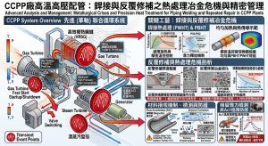
在全球能源轉型與電網極端負載調度需求日益嚴苛的趨勢下,次世代複循環發電廠(Combined Cycle Power Plant, CCPP)的高溫高壓動力管線系統正面臨前所未有的力學與流體動力學挑戰。以台灣電力公司於苗栗推動的通霄電廠第二期更新改建計畫為例,該專案預計拆除舊有之第四號與第五號機組,並新建五部尖端的高效率燃氣複循環機組1。這類現代化機組的操作特性要求頻繁的起停機(Two-shifting)與極為快速的負載升降,使得內部輸送高溫高壓蒸汽的動力管線承受著極端且反覆的流固耦合(Fluid-Structure Interaction, FSI)破壞條件。過去在電廠建置階段,工程界大量依賴曲率半徑極小的傳統短半徑銲接彎頭(如 1.5D 彎頭);然而,隨著運轉參數的提升,這類傳統管線設計已逐漸無法滿足長達數十年的安全運轉需求。流體加速腐蝕(Flow-Accelerated Corrosion, FAC)與暫態水錘破壞,已成為威脅電廠可用率與人員安全的核心隱患,亟需從流體力學與結構力學的根源上尋求突破性的解決方案。 Driven by the global energy transition and the increasingly stringent demands of extreme grid load dispatching, the high-temperature and high-pressure power piping systems in next-generation Combined Cycle Power Plants (CCPP) face unprecedented mechanical and fluid dynamic challenges. Take Taiwan Power Company’s Tongxiao Power Plant Phase II Renewal and Upgrading Project in Miaoli as an example. The project plans to dismantle the legacy Unit 4 and Unit 5 to construct five cutting-edge, high-efficiency gas-fired combined cycle units1. The operational characteristics of these modern units require frequent two-shifting and extremely rapid load ramping, subjecting the internal power piping—which transports high-temperature, high-pressure steam—to extreme and cyclic fluid-structure interaction (FSI) damage conditions. Historically, the engineering sector relied heavily on traditional short-radius welded elbows (such as 1.5D elbows). However, as operating parameters have escalated, these conventional piping designs can no longer guarantee decades of safe operation. Flow-Accelerated Corrosion (FAC) and transient water hammer damage have emerged as critical threats to plant availability and personnel safety, urgently necessitating breakthrough solutions rooted in fundamental fluid and structural mechanics.
1.1 高溫高壓流場之暫態現象與力學衝擊 / 1.1 Transient Phenomena and Mechanical Impact in High-Temperature, High-Pressure Flow Fields
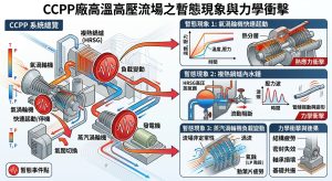
在複循環電廠的實際運轉生命週期中,動力管線內部的流場絕大多數時間並非處於理想的穩態(Steady-state)。當機組經歷冷態啟動、溫態啟動,或是因應電網需求急遽改變負載時,管線內部會頻繁誘發各類劇烈的流體暫態現象。其中,蒸汽水錘(Steam Hammer)與冷凝水錘(Condensation-Induced Water Hammer, CIWH)對管線結構所造成的瞬間衝擊破壞力最為深遠2。蒸汽水錘現象通常發生在汽輪機快速截流閥(Fast Stop Valve)或控制閥緊急關閉的瞬間。此時,以極高速度流動的高壓主蒸汽被強行阻斷,流體的龐大動能瞬間轉換為壓力勢能,形成強烈的壓力波,並以音速沿著管線逆向傳遞。根據流體力學中的茹可夫斯基方程式(Joukowsky Equation),瞬間的壓力突升量與流體密度、聲速及流速的變化量成絕對正比關係。當這股高壓震波傳遞至管線系統的轉彎處,尤其是曲率極度不連續的傳統 90 度銲接彎頭時,由於流動方向被強制且劇烈地改變,流體動量守恆的變化會對彎頭外弧側產生巨大的不平衡推力(Unbalanced Force),進而引發管線的劇烈震動與支架破壞。 Throughout the actual operational lifecycle of a CCPP, the flow field inside the power piping is rarely in an ideal steady-state. When the unit undergoes cold starts, warm starts, or sudden load changes in response to grid demands, various severe fluid transient phenomena are frequently induced. Among these, Steam Hammer and Condensation-Induced Water Hammer (CIWH) inflict the most profound instantaneous impact damage on the piping structure2. Steam hammer typically occurs the moment a turbine’s fast stop valve or control valve is emergency-closed. The highly accelerated high-pressure main steam is forcibly blocked, converting massive kinetic energy instantly into pressure potential energy. This forms a strong pressure wave that travels upstream at the speed of sound. According to the Joukowsky Equation in fluid mechanics, the instantaneous pressure surge is directly proportional to fluid density, the speed of sound, and the change in flow velocity. When this high-pressure shockwave reaches a bend—especially a traditional 90-degree welded elbow with highly discontinuous curvature—the forced, drastic change in flow direction results in a massive unbalanced force on the extrados (outer curve) due to momentum conservation, triggering violent pipe vibrations and support failure.
除了水錘效應之外,熱階層化(Thermal Stratification)現象亦是高溫動力管線在低流量運轉或暖管階段常見的致命問題。當管內流速較低,流體的慣性力無法克服浮力時,高溫蒸汽與底部的冷凝水會因為密度差異而在水平管段產生嚴重的分層現象。這種頂部與底部之間極大的溫度梯度,會導致管線截面產生非對稱的熱膨脹,進而引發管線整體的「弓形變形」(Bowing Effect)。若此類熱變形受到剛性管架或設備終端的拘束,將在管壁內部產生極高的熱二次應力(Thermal Secondary Stress)。當這些熱應力與水錘產生的動態一次應力在傳統銲道熱影響區(Heat-Affected Zone, HAZ)疊加時,極易誘發低周波疲勞裂紋,甚至導致管線無預警斷裂。In addition to the water hammer effect, thermal stratification is a fatal issue commonly encountered in high-temperature power piping during low-flow operations or warming stages. When the internal flow velocity is low and the fluid’s inertia cannot overcome buoyancy, the density difference between the high-temperature steam and the condensate at the bottom causes severe stratification in horizontal pipe sections. The extreme temperature gradient between the top and bottom causes asymmetrical thermal expansion of the pipe cross-section, inducing a global “Bowing Effect.” If this thermal deformation is constrained by rigid pipe supports or equipment terminals, extremely high thermal secondary stresses are generated within the pipe wall. When these thermal stresses superimpose with the dynamic primary stresses from water hammer in the heat-affected zone (HAZ) of traditional welds, low-cycle fatigue cracks are easily induced, potentially leading to catastrophic, unpredicted pipe rupture.
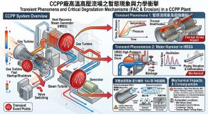
1.2 流體加速腐蝕 (FAC) 與沖刷腐蝕機制 / 1.2 Flow-Accelerated Corrosion (FAC) and Erosion-Corrosion Mechanisms
流體加速腐蝕(FAC)是碳鋼及低合金鋼在高溫純水或濕蒸汽環境中,因流體動力學與電化學交互作用而導致管壁快速且均勻減薄的致命退化機制。其化學反應的本質在於,管壁表面原本具備保護性的磁鐵礦(Fe3O4)氧化層,在局部高紊流的沖刷與剪切力作用下,不斷溶解為亞鐵離子(Fe2+)並被流體帶走。FAC 的核心氧化還原反應可透過電化學方程式精確描述:金屬鐵首先與水反應生成亞鐵離子與氫氣( Fe+2H2O→Fe2++2OH–+H2),隨後進一步轉化為氫氧化亞鐵,並在特定條件下生成磁鐵礦(3Fe(OH)2↔Fe3O4+2H2O+H2)3。然而,在 FAC 活躍的區域,磁鐵礦的生成速率遠低於其被流體剝離與溶解的速率。 Flow-Accelerated Corrosion (FAC) is a fatal degradation mechanism in carbon and low-alloy steels exposed to high-temperature pure water or wet steam, causing rapid and uniform wall thinning due to the interaction of fluid dynamics and electrochemistry. The fundamental chemical mechanism involves the inherently protective magnetite (Fe3O4) oxide layer on the pipe wall surface being continuously dissolved into ferrous ions (Fe2+) and carried away by the fluid under the scouring and shear forces of local high turbulence. The core redox reaction of FAC is precisely described by electrochemical equations: metallic iron first reacts with water to form ferrous ions and hydrogen gas (Fe+2H2O→Fe2++2OH–+H2), which further converts into ferrous hydroxide and, under specific conditions, forms magnetite (3Fe(OH)2↔Fe3O4+2H2O+H2)3. However, in FAC-active regions, the formation rate of magnetite is vastly outpaced by its fluid-driven stripping and dissolution rates.
在流體力學與熱傳學層面,FAC 的減薄速率高度依賴於質傳係數(Mass Transfer Coefficient, MTC)3。根據 EPRI 所開發的 Chexal-Horowitz 模型以及歐洲廣泛採用的 Kastner 模型,質傳係數是流場雷諾數(Re)、施密特數(Sc)與流場幾何特徵的高度非線性函數。其核心的無因次經驗公式可表示為 Sh=a⋅Reb⋅Scc(其中 Sh 為薛伍德數,代表總質傳與擴散質傳的比率)3。此外,Kastner 等人的研究進一步指出,管件的幾何形狀對 FAC 速率具有決定性的影響,並提出了距離效應(Proximity Effect)的修正公式,證明了幾何突變點下游的紊流會呈指數型放大質量傳遞3。 On the fluid dynamics and heat transfer fronts, the FAC thinning rate relies heavily on the Mass Transfer Coefficient (MTC)3. According to the Chexal-Horowitz model developed by EPRI and the widely adopted Kastner model in Europe, the MTC is a highly non-linear function of the Reynolds number (Re), Schmidt number (Sc), and geometric flow characteristics. The core dimensionless empirical formula is expressed as Sh=a⋅Reb⋅Scc (where Sh is the Sherwood number, representing the ratio of total mass transfer to diffusive mass transfer)3. Furthermore, Kastner’s research indicates that fitting geometry decisively influences the FAC rate, proposing a correction formula for the Proximity Effect, which proves that turbulence downstream of geometric discontinuities exponentially amplifies mass transfer3.
在傳統的 1.5D 短半徑銲接彎頭內部,由於幾何曲率半徑極小,流體在通過彎道時會受到強烈的向心加速度與離心力作用,導致流場內部產生極大的徑向壓力梯度。這種壓力失衡會迫使邊界層內的低速流體從高壓的外弧側向低壓的內弧側流動,最終在管線截面上形成兩股反向旋轉的二次流,即流體力學中著名的「迪恩渦流」(Dean Vortices)8。迪恩渦流的強度可由無因次的迪恩數(Dean Number, De)進行幾何與流體力學的精確量化,其方程式為 De=Re√D/2Rc,其中 Re 為雷諾數,D 為管線內徑,Rc 為彎管的中心曲率半徑12。由該方程式可以清晰地推導出,當採用傳統 1.5D 短半徑彎頭時,Rc 處於極小值,導致迪恩數呈指數級放大。異常強烈的迪恩渦流會徹底破壞管壁邊界層的黏滯底層,使得局部的質傳係數(MTC)激增。數值流體力學(CFD)的模擬結果一致顯示,在傳統彎頭 45° 至 60° 的彎角區間,流速與紊流動能達到絕對峰值,這正是 FAC 質量流失最為嚴重的區域10。更甚者,傳統彎頭與直管對接處的銲道,尤其是內部未完全磨平的銲根突起,會成為流場中的物理幾何突變點,進一步誘發流體分離(Flow Separation)與尾流旋渦,導致銲道下游的 FAC 速率呈現非線性的加速惡化,迫使管壁在設計壽命終期之前便提早達到 ASME 規範定義的安全厚度極限值。 Inside traditional 1.5D short-radius welded elbows, the extremely small radius of curvature subjects the fluid to intense centripetal acceleration and centrifugal forces, generating a massive radial pressure gradient within the flow field. This pressure imbalance forces low-velocity fluid in the boundary layer to flow from the high-pressure extrados to the low-pressure intrados (inner curve), ultimately forming two counter-rotating secondary flows across the pipe cross-section, known in fluid mechanics as “Dean Vortices”8. The intensity of Dean Vortices can be precisely quantified geometrically and fluid-dynamically by the dimensionless Dean Number (De), formulated as De=Re√D/2Rc, where Re is the Reynolds number, D is the pipe’s internal diameter, and Rc is the center radius of curvature of the bend12. This equation clearly deduces that when a traditional 1.5D elbow is used, Rc is at a minimum, causing the Dean Number to amplify exponentially. Abnormally strong Dean Vortices completely destroy the viscous sublayer of the pipe wall boundary, causing localized MTC to surge. Computational Fluid Dynamics (CFD) simulations consistently show that flow velocity and turbulent kinetic energy reach absolute peaks in the 45° to 60° angle range of traditional elbows, which coincides exactly with the zone of most severe FAC mass loss10. Furthermore, the weld seams connecting the elbow to straight pipes—especially the unground weld root protrusions—act as physical geometric discontinuities in the flow field. These induce flow separation and wake vortices, leading to a non-linear accelerated deterioration of the FAC rate downstream of the weld, forcing the pipe wall to reach the ASME-defined safe thickness limit prematurely before the end of its design life.
二、 ASME B31J 規範於管線流固耦合(FSI)之應用 / 2. Application of ASME B31J Code in Piping Fluid-Structure Interaction (FSI)
為了精確評估前述流體力學暫態現象與管壁減薄對管線結構疲勞壽命的影響,現代高能管線設計標準已經全面揚棄了過度保守且單一的舊版規範,轉而強制導入更符合三維實體力學行為的 ASME B31J 規範。這一轉變標誌著動力管線應力分析正式從 1950 年代基於薄壁管件的平面疲勞理論,邁入以先進有限元素分析(FEA)與真實多軸疲勞試驗為基礎的新紀元13。 To accurately evaluate the impact of the aforementioned fluid dynamic transient phenomena and wall thinning on the fatigue life of piping structures, modern high-energy piping design standards have entirely abandoned overly conservative and singular legacy codes. Instead, they mandate the adoption of the ASME B31J code, which better aligns with 3D solid mechanical behavior. This transition marks the official evolution of power piping stress analysis from 1950s planar fatigue theories based on thin-walled components into a new era founded on advanced Finite Element Analysis (FEA) and real-world multi-axial fatigue testing13.
2.1 應力強化係數 (SIF) 與幾何參數之關聯 / 2.1 Correlation Between Stress Intensification Factors (SIF) and Geometric Parameters
追溯動力管線應力分析的歷史,最早期的應力強化係數(Stress Intensification Factor, SIF 或 i)概念是由 A.R.C. Markl 等人於 1950 年代透過廣泛的疲勞測試所提出。Markl 將標準直管對接銲縫的疲勞基線 SIF 值設定為 1.0,並推導出描述管件疲勞破壞行為的經典方程式 iSa=245,000N-0.2,其中 Sa 為標稱應力振幅,N 為引發疲勞破壞的循環次數13。半個多世紀以來,這個基於有限實驗數據的單一 SIF 值,一直被收錄於 ASME B31.1 與 B31.3 的 Appendix D 之中,作為計算管件柔性與應力的唯一圭臬13。在舊版規範下,工程師計算彎管的 SIF 時僅採用單一的純量值,並將其同等地應用於面內與面外的彎矩計算14。這種做法完全忽視了管件在不同空間向量受力下的真實幾何剛度差異,往往導致系統被過度設計(Over-engineered),不僅增加了不必要的剛性管架與阻尼器,更將巨大的熱膨脹推力轉移至脆弱的設備噴嘴上13。 Tracing the history of power piping stress analysis, the earliest concept of the Stress Intensification Factor (SIF or i) was proposed by A.R.C. Markl and colleagues through extensive fatigue testing in the 1950s. Markl set the baseline fatigue SIF for standard straight pipe girth butt welds at 1.0 and derived the classic equation describing component fatigue failure behavior: iSa=245,000N-0.2, where Sa is the nominal stress amplitude and N is the number of cycles to fatigue failure13. For over half a century, this singular SIF value based on limited empirical data remained in Appendix D of ASME B31.1 and B31.3 as the sole criterion for calculating component flexibility and stress13. Under legacy codes, engineers calculated an elbow’s SIF using a single scalar value, applying it equally to both in-plane and out-of-plane bending moments14. This practice completely ignored the true geometric stiffness differences of components under different spatial force vectors, often resulting in over-engineered systems. This not only added unnecessary rigid pipe supports and snubbers but also transferred massive thermal expansion thrusts onto vulnerable equipment nozzles13.
ASME B31J 規範的革命性意義,在於其將應力強化係數與柔性係數進行了嚴謹的空間解耦,將其拆分為三個獨立的三維空間分量:面內應力強化係數(ii)、面外應力強化係數(io)以及扭轉應力強化係數(it)13。對於彎管這類核心管件而言,其應力集中的程度高度取決於無因次的「柔性特徵值」(Flexibility Characteristic, h)12。依據 B31J 規範的數學定義,柔性特徵值的方程式為h=T⋅R1/r22,其中 T 代表彎管的公稱壁厚(Nominal wall thickness),R1 為幾何彎曲半徑(Bend radius),r2 則是連接直管的平均截面半徑12。從此方程式的分子結構可以直觀且科學地看出,R1 的大小直接決定了 h 值的高低。這意味著,當電廠設計將傳統的 1.5D 短半徑彎頭升級替換為 5D 大半徑冷作彎管時,R1 實質上放大了 3.33 倍,其柔性特徵值 h 亦隨之呈現線性倍增。較大的 h 值代表管件具備極強的截面穩定性,能夠有效抵抗因巨大彎矩所引發的截面畸變(Distortion)與橢圓化(Ovality)現象12。 The revolutionary significance of the ASME B31J code lies in its rigorous spatial decoupling of stress intensification and flexibility factors, dividing them into three independent 3D spatial components: In-Plane SIF (ii), Out-of-Plane SIF (io), and Torsional SIF (it)13. For core components like bends, the degree of stress concentration relies heavily on the dimensionless “Flexibility Characteristic” (h)12. According to the mathematical definition in B31J, the flexibility characteristic equation is h=T⋅R1/r22, where T is the bend’s nominal wall thickness, R1 is the geometric bend radius, and r2 is the mean cross-sectional radius of the matching pipe12. The molecular structure of this equation intuitively and scientifically reveals that the magnitude of R1 directly determines the value of h. This implies that when a plant design upgrades from traditional 1.5D short-radius elbows to 5D large-radius cold bends, R1 is essentially amplified by 3.33 times, resulting in a linear doubling of the flexibility characteristic h. A larger h value signifies that the component possesses exceptional cross-sectional stability, effectively resisting section distortion and ovality induced by massive bending moments12.
在 ASME B31J 的最新演進中,針對彎矩作用方向的不同,其精確的邊界修正定義涵蓋了三個維度。首先是面內方向,當彎矩作用於彎管所在的幾何平面內,導致彎頭產生張角「打開(Opening)」或「閉合(Closing)」的變形趨勢時,應用面內應力強化係數(ii)與柔性係數(ki)13。傳統上 ii 定義為0.9/h2/3,而 B31J 則根據大量 FEA 數據導入了更精確的非線性邊界修正12。其次是面外方向,當彎矩的作用向量垂直於彎管平面,迫使管件發生橫向「扭曲(Twisting)」時,應用面外應力強化係數(io),其傳統基礎公式為0.75/h2/3 8。最具突破性的是扭轉方向,B31J 規範首度在管線動態與位移應力分析中,針對多種管件強制導入了扭轉應力強化係數(it≠1.0)的條件12。打破過去將扭轉 SIF 預設為 1.0 的盲區,對於精確計算管網熱膨脹轉移至末端高速旋轉機械(如 CCPP 中的高壓汽輪機或大型離心式壓縮機)的噴嘴荷重(Nozzle loads)至關重要,有效避免了設備軸心偏移與劇烈振動的風險12。 In the latest evolution of ASME B31J, precise boundary corrections are defined across three dimensions based on the bending moment’s direction of action. First is the In-Plane direction: when the bending moment acts within the geometric plane of the bend, causing the elbow to tend to deform by “Opening” or “Closing,” the in-plane SIF (ii) and flexibility factor (ki) are applied13. Traditionally, ii was defined as 0.9/h2/3, while B31J introduces precise non-linear boundary corrections based on extensive FEA data12. Second is the Out-of-Plane direction: when the action vector of the bending moment is perpendicular to the bend plane, forcing the component to undergo lateral “Twisting,” the out-of-plane SIF (io) is applied, with a traditional base formula of 0.75/h2/3 8. The most groundbreaking addition is the Torsional direction: for the first time in piping dynamic and displacement stress analyses, B31J mandates torsional SIF (it≠1.0) conditions for various fittings12. Breaking away from the blind spot of defaulting torsional SIF to 1.0 is vital for accurately calculating nozzle loads transferred from pipe network thermal expansion to terminal high-speed rotating machinery (e.g., high-pressure steam turbines or large centrifugal compressors in CCPPs), effectively averting risks of shaft misalignment and severe vibrations12.
| 力學分析參數 / Mechanical Analysis Parameter | 傳統 ASME B31.1/B31.3 附錄D (已廢除) / Legacy ASME B31.1/B31.3 Appendix D (Abolished) | 最新 ASME B31J 規範 (強制導入) / Latest ASME B31J Code (Mandatory) | 系統力學與工程影響分析 / System Mechanics & Engineering Impact |
| SIF 處理方式 / SIF Handling Method | 單一最大純量值,統一乘入合成彎矩中 / Single maximum scalar value, uniformly multiplied into resultant moment. | 空間嚴格解耦為獨立的面內(ii)、面外(io)與扭轉(it)分量21 / Spatially decoupled strictly into independent in-plane (ii), out-of-plane (io), and torsional (it) components. | 徹底消除因方向疊加導致的虛假應力超標,能極度精確定位真實的疲勞破壞熱點13 / Completely eliminates false stress exceedance caused by directional superposition, precisely locating true fatigue hotspots. |
| 柔性係數 (k) / Flexibility Factor (k) | 單一純量,完全忽略厚壁管對扁平化效應的剛度補償13 / Single scalar, totally ignoring stiffness compensation of thick-walled pipes against ovalization. | 空間解耦為三維獨立參數,真實反映幾何剛度13 / Spatially decoupled into 3D independent parameters, reflecting true geometric stiffness. | 精確預測系統節點的熱膨脹位移,避免盲目增設昂貴的剛性管架與油壓阻尼器 / Accurately predicts nodal thermal expansion displacement, avoiding blind addition of expensive rigid supports and snubbers. |
| 持續應力指數 / Sustained Stress Index | 經常與疲勞 SIF 混用,導致厚度設計過度保守 / Often mixed with fatigue SIF, leading to overly conservative thickness designs. | 獨立定義 SSI (Sustained Stress Index),取 max(0.75i,1.0)14 / Independently defines SSI (Sustained Stress Index), taking max(0.75i,1.0). | 防止管線在自重與內壓下發生不可逆的塑性塌陷,賦予管線佈局更高的彈性12 / Prevents irreversible plastic collapse of piping under self-weight and internal pressure, granting higher flexibility in layout. |
2.2 極限值對疲勞壽命之影響與高溫潛變交互作用 / 2.2 Impact of Limit Values on Fatigue Life and High-Temperature Creep Interaction
動力管線在承受內部蒸汽高溫高壓的一次應力(Primary Stress)的同時,亦承受著由熱膨脹受阻所引發的交變二次應力(即位移應力範圍,Displacement Stress Range, SE)。B31J 規範透過精密的合成應力方程式來評估此一效應:SE=√((iiMi)2+(ioMo)2+(itMt)2 )/Ze 16。當傳統管件(如 1.5D 短彎頭)在製造過程中的瑕疵,或是因冷彎工法不佳導致的幾何形變(如截面橢圓度逼近或超過規範允許的 8%、外弧減薄率過大)逼近規範極限值時,其柔性特徵值 h 會顯著下降,導致對應的 SIF 值呈幾何級數上升。這將使得管壁局部產生極高水平的峰值應力(Peak Stress)。 In addition to bearing primary stresses from high-temperature and high-pressure internal steam, power piping simultaneously endures alternating secondary stresses (i.e., Displacement Stress Range, SE) induced by constrained thermal expansion. The B31J code evaluates this effect through a precise resultant stress equation: SE=√((iiMi)2+(ioMo)2+(itMt)2 )/Ze 16. When flaws in traditional components (like 1.5D short elbows) during manufacturing, or geometric deformations caused by poor cold-bending processes (such as cross-sectional ovality approaching or exceeding the code-allowed 8%, or excessive extrados thinning), approach code limits, the flexibility characteristic h drops significantly. This causes corresponding SIF values to rise exponentially, generating extremely high peak stresses locally within the pipe wall.
在通霄二期 CCPP 高達 600°C 以上的超臨界運轉環境中,材料不僅面臨常規的機械疲勞,更面臨冶金學上極為致命的「潛變-疲勞交互作用」(Creep-Fatigue Interaction)9。持續的機械負載(如管線自重與內部高壓)會引發材料晶界處產生潛變空洞(Creep voids),而機組頻繁起停機所產生的交變熱應力,則會加速這些微觀空洞的連結與疲勞裂紋的擴展。為求真實反映多軸疲勞與複雜厚壁管件的失效機制,ASME 最新規範對疲勞計算進行了重大修正。在長達 70 年的時間裡,容許應力循環係數 f 的計算公式為 f=6.0N-0.2,這隱含了 S-N(應力-壽命)曲線的斜率為 5:1。然而,最新的規範將公式嚴格修正為f=20N-0.333,將 S-N 曲線斜率調整為 3:1。力學分析表明,這兩條疲勞曲線在循環次數 N≈2×10⁴ 時交叉;當循環次數超過此極限值並進入高周波疲勞區間(如頻繁起停或受流體連續震動的製程管線)時,新的 f 值將呈現斷崖式下跌。這深刻地意味著,若工程界繼續沿用內部流場擾動巨大、極易產生局部高應力集中的傳統銲接彎頭,管線結構將極度容易在設計壽命終期之前,發生無預警的疲勞破裂與災難性失效。 In the supercritical operating environment of Tongxiao Phase II CCPP, which exceeds 600°C, the material faces not only conventional mechanical fatigue but also a metallurgically fatal “Creep-Fatigue Interaction”9. Sustained mechanical loads (such as pipe self-weight and internal high pressure) induce creep voids at the material’s grain boundaries, while alternating thermal stresses generated by frequent unit start-ups and shutdowns accelerate the linkage of these micro-voids and the propagation of fatigue cracks. To truthfully reflect multi-axial fatigue and the failure mechanisms of complex thick-walled fittings, the latest ASME codes have substantially revised fatigue calculations. For 70 years, the allowable stress cycle factor f was calculated as f=6.0N-0.2, implying a 5:1 slope for the S-N (Stress-Life) curve. However, the newest code strictly corrects the formula to f=20N-0.333, adjusting the S-N curve slope to 3:1. Mechanical analysis shows these two fatigue curves intersect at approximately N≈2×10⁴ cycles; once cycle counts surpass this limit and enter the high-cycle fatigue regime (e.g., process piping subjected to frequent start-stops or continuous fluid vibration), the new f value drops precipitously. This profoundly signifies that if the engineering industry continues to utilize traditional welded elbows—which suffer massive internal flow disturbances and easily generate local high-stress concentrations—the piping structure will be extremely prone to unpredictable fatigue rupture and catastrophic failure well before the end of its design life.
三、 3D與5D CNC冷管彎工法對流場之優化機制 / 3. Flow Field Optimization Mechanisms of 3D and 5D CNC Cold Bending Methods
面對嚴苛的 ASME B31J 力學檢驗與流體加速腐蝕(FAC)的實體減薄威脅,通霄二期 CCPP 專案的 EPC 統包商(如中鼎工程與 Mitsubishi Power)導入了具備前瞻視野的「去銲接化」管線佈局策略,其核心硬體載體即為 3D 與 5D CNC 冷作彎管(Cold Bending)工法1。此技術不僅僅是製造工法上的升級,更是從流體動力學與固體力學的根源上,一舉解決高能管線失效的完美方案。 Faced with rigorous ASME B31J mechanical verification and the physical thinning threats of Flow-Accelerated Corrosion (FAC), the EPC contractors of the Tongxiao Phase II CCPP project (such as CTCI and Mitsubishi Power) introduced a forward-looking “Weldless” piping layout strategy. Its core hardware carrier is the 3D and 5D CNC Cold Bending method1. This technology is not merely a manufacturing upgrade; rather, it is a perfect solution that conclusively resolves high-energy piping failures from the very roots of fluid and solid mechanics.
3.1 消除流場擾動與去銲接化優勢 / 3.1 Eliminating Flow Disturbances and the Advantages of “Weldless” Design
在傳統的高能管線佈局中,直管與 1.5D 短半徑彎頭之間必須高度依賴現場的環向對接銲縫(Girth Butt Weld)進行連接。在微觀流體力學的嚴苛視角下,即便銲接品質再優良、非破壞性檢測(NDT)全數合格,銲根內部的微小突起、銲波起伏或是內徑的微小不匹配(Mismatch),皆構成了流場邊界層中不可忽視的物理幾何障礙。這些幾何不連續性會強制剝離原本平順的層流邊界層,在銲道下游產生強烈的流體尾流與微觀旋渦,使得局部的流體紊流動能(Turbulence Kinetic Energy, k)與耗散率(ϵ)急遽升高3。根據 Kastner FAC 模型的距離效應(Proximity Effect)研究,相鄰管件或銲縫所引發的流場干擾會呈現指數型的 FAC 加速惡化,其修正公式可表達為e-0.231⋅L/D×100%。這證實了銲道的存在本身就是一個強大的腐蝕加速器。 In traditional high-energy piping layouts, connections between straight pipes and 1.5D short-radius elbows rely heavily on field Girth Butt Welds. Under the strict lens of micro-fluid dynamics, even with excellent welding quality and a 100% pass rate in Non-Destructive Testing (NDT), minute protrusions at the weld root, weld bead ripples, or slight internal diameter mismatches constitute non-negligible physical geometric barriers in the flow boundary layer. These geometric discontinuities forcefully strip away the originally smooth laminar boundary layer, creating intense fluid wakes and micro-vortices downstream of the weld, which sharply increase local Turbulence Kinetic Energy (k) and dissipation rate (ϵ)3. According to the Kastner FAC model’s Proximity Effect research, flow interference caused by adjacent fittings or welds exhibits exponential FAC acceleration, with the correction formula expressed as e-0.231⋅L/D×100%. This confirms that the mere presence of a weld seam acts as a potent corrosion accelerator.
3D 與 5D CNC 冷作彎管工法透過大型伺服數控彎管設備,將數公尺長的特厚無縫鋼管直接在常溫下一體成形,塑造出連續且極度平滑的曲率過渡段。此「去銲接化」的革命性設計,徹底消除了彎管與直管連接處的銲道,猶如拔除了管線內部的首要擾流源13。更為關鍵的是,透過將彎曲半徑從傳統的 1.5D 提升至 3D 甚至 5D,根據前述的迪恩數(De)方程式,曲率半徑 Rc的大幅增加將使得迪恩數呈幾何級數下降,從而極大地削弱了二次流(迪恩渦流)的旋轉強度。計算流體力學(CFD)與質量傳遞模擬一致證實,5D 彎管內的流速與壓力分佈遠比 1.5D 彎頭對稱平緩,外弧側的峰值流速與離心壓力梯度被大幅抹平。這種流場的穩定化直接導致了邊界層質量傳遞係數(MTC)的驟降,從最根本的物理化學機制上扼殺了 FAC 快速發展的溫床,確保了管壁厚度在數十年的服役期內維持穩定。 The 3D and 5D CNC cold bending method utilizes large servo-controlled bending equipment to integrally form several meters of extra-thick seamless steel pipes at room temperature, crafting a continuous and extremely smooth curvature transition. This revolutionary “Weldless” design completely eliminates the weld seams at the junction between the bend and straight pipes, essentially uprooting the primary source of flow disturbance inside the piping13. Crucially, by increasing the bend radius from the traditional 1.5D to 3D or even 5D, according to the aforementioned Dean Number (De) equation, the substantial increase in the radius of curvature Rc causes the Dean Number to decrease exponentially, thereby vastly weakening the rotational intensity of secondary flows (Dean Vortices). Computational Fluid Dynamics (CFD) and mass transfer simulations unanimously confirm that velocity and pressure distributions inside a 5D bend are far more symmetrical and gradual than in a 1.5D elbow, drastically flattening peak velocities and centrifugal pressure gradients on the extrados. This flow field stabilization directly induces a plunge in the boundary layer’s Mass Transfer Coefficient (MTC), smothering the hotbed for rapid FAC development from fundamental physico-chemical mechanisms and ensuring the pipe wall thickness remains stable over decades of service.
3.2 真圓度與減薄率之精密控制 / 3.2 Precision Control of Ovality and Wall Thinning Rate
儘管冷彎工法在流體力學上展現出壓倒性優勢,但管線在冷彎成形的過程中,因受到機台純彎矩與拉壓應力的共同嚴酷作用,外弧側(Extrados)的金屬纖維必然會產生塑性拉伸進而導致壁厚減薄(Thinning);同時,內弧側(Intrados)則受到強烈壓縮而增厚,並伴隨管截面向中性軸方向壓扁,產生一定程度的橢圓度(Ovality)變形24。這種冷作變形對金屬微觀組織的物理破壞程度,可由極限纖維的理論塑性應變率(Plastic Strain Rate, ϵ)進行幾何量化。基於幾何應變關係,其計算公式為ϵ=ro/R1 ×100%=Do/(2R1)×100% 12。將主流的曲率半徑代入計算可知,3D 彎管的最大成形應變率高達約 16.67%,而 5D 彎管的最大成形應變率則收斂至約 10.0%。 Although the cold bending method demonstrates overwhelming fluid dynamic advantages, during the forming process, the pipe is subjected to the severe combined effects of the machine’s pure bending moment and tensile-compressive stresses. Consequently, metal fibers on the extrados inevitably undergo plastic stretching, leading to wall thinning; simultaneously, the intrados is heavily compressed and thickened, accompanied by the pipe cross-section flattening toward the neutral axis, generating a certain degree of ovality deformation24. The extent of physical damage to the metal’s microstructure from this cold deformation can be geometrically quantified by the theoretical Plastic Strain Rate (ϵ) of the extreme fibers. Based on geometric strain relationships, the formula is ϵ=ro/R1 ×100%=Do/(2R1)×100% 12. Substituting mainstream curvature radii into the calculation reveals that the maximum forming strain rate for a 3D bend is approximately 16.67%, whereas it converges to about 10.0% for a 5D bend.
若不加以精密控制,過大的橢圓度與不受控的減薄率將嚴重削弱管線承受內壓的能力,並直接放大 ASME B31J 的 SIF 值。為了確保受壓邊界的絕對安全,設計厚度 tm 的計算必須嚴格遵循修正後的 Barlow 方程式,並引入應力重分配修正係數 I。針對外弧側的減薄補償, Iextrados=[4(R/D)+1]/[4(R/D)+2];而內弧側的受壓餘裕則為 Iintrados=[4(R/D)-1]/[4(R/D)-2] 24。 Left un-precisely controlled, excessive ovality and unchecked thinning will severely weaken the pipe’s internal pressure-bearing capacity and directly amplify ASME B31J SIF values. To ensure the absolute safety of the pressure boundary, the calculation of the design thickness tm must strictly follow the modified Barlow equation and incorporate the stress redistribution correction factor I. For extrados thinning compensation, Iextrados=[4(R/D)+1]/[4(R/D)+2]; while for intrados pressure margins, Iintrados=[4(R/D)-1]/[4(R/D)-2] 24.
在現代化的工廠預製流程中,頂尖製造商必須運用 CNC 伺服控制系統,配合內部精密芯軸(Mandrel)與外部增壓推進裝置(Booster),對金屬的塑性流動進行三維實時的力學干預。透過這些精細的參數控制,5D 彎管的橢圓度通常能被嚴格壓制在 ASME B16.49 規範容許的 8% 以內,在優良的工法下甚至常態性達到 < 3% 的航太級優異水準13。針對外弧減薄,工程設計階段即依據 ASME B31.1 的法定要求,預先指導 EPC 統包商採購具有特定補償裕度(Allowance)的母管。這種從幾何物理層面達成的高精度控制,確保了管線在承受極端暫態流體衝擊時的結構完整性。 In modernized factory prefabrication workflows, top-tier manufacturers must deploy CNC servo control systems, coordinating internal precision mandrels with external boosters to exert real-time 3D mechanical intervention on the metal’s plastic flow. Through such refined parameter controls, the ovality of 5D bends can typically be strictly suppressed within the ASME B16.49 code allowance of 8%, routinely achieving an aerospace-grade level of < 3% under superior processes13. Regarding extrados thinning, engineering designs instruct EPC contractors in advance to procure parent pipes with specific allowances, conforming to ASME B31.1 statutory requirements. This high-precision control achieved at the geometric and physical levels guarantees the structural integrity of the piping when enduring extreme transient fluid impacts.
| 彎管幾何半徑比 (R/D) / Bend Radius Ratio (R/D) | ASME 法定壁厚減薄補償餘裕 / ASME Statutory Wall Thinning Allowance | 幾何成形應變率 (ϵ) / Geometric Forming Strain Rate (ϵ) | 流體力學與工程經濟學綜合評估 / Comprehensive Fluid Dynamics & Engineering Economics Assessment |
| 1.5D 銲接彎頭 / 1.5D Welded Elbow | N/A (通常為鑄造或鍛造預成形 / Usually cast or forged preform) | N/A | 迪恩渦流極強,FAC 減薄風險位於危險紅區;需額外進行現場環銲,強行引入幾何擾動與 MTC 峰值。 / Extremely strong Dean Vortices; FAC thinning risk in the red zone. Requires additional field girth welds, forcing geometric disturbances and MTC peaks. |
| 3D CNC 冷作彎管 / 3D CNC Cold Bend | 1.25 tm (需預留 25% 餘裕 / Requires 25% allowance) | 16.67% | 材料成本劇增區。局部減薄率極高,必須採購特製的超厚母管以應對厚度損失,大幅推高整廠建置成本。 / Material cost spike zone. Extremely high local thinning demands custom extra-heavy parent pipes, drastically inflating plant construction costs. |
| 5D CNC 冷作彎管 / 5D CNC Cold Bend | 1.08 tm (需預留 8% 餘裕 / Requires 8% allowance) | 10.00% | 工程經濟學最佳平衡點。8% 餘裕絕大多數可由市售標準 Schedule 鋼管的正公差吸收;曲率極度平滑,迪恩渦流顯著消散,全面抑制 FAC20。 / Optimal engineering economics balance. The 8% allowance is mostly absorbed by the positive tolerance of standard commercial Schedule pipes. Extremely smooth curvature dissipates Dean Vortices, comprehensively inhibiting FAC20. |
四、 高溫動力管線之單管感應加熱 (IH-PBHT) 冶金強化 / 4. Metallurgical Strengthening of High-Temperature Power Piping via Single-Pipe Induction Heating (IH-PBHT)
雖然冷彎工法在流體力學消能與應力幾何分佈上具備壓倒性的系統優勢,但高達 10% 至 16.67% 的巨量塑性應變會使合金鋼內部的位錯密度(Dislocation density)急遽增加,產生巨大的加工硬化與殘留應力。這對於通霄二期 CCPP 廣泛採用以承受超臨界溫度的先進耐熱鋼(如 ASTM A335 P91 / P92)而言,是極為致命的隱患。若不進行精準的冶金熱處理干預,管線將面臨早期潛變斷裂的毀滅性風險。While the cold bending method boasts overwhelming systemic advantages in fluid dynamic energy dissipation and geometric stress distribution, the massive plastic strain—ranging from 10% to 16.67%—sharply increases dislocation density within the alloy steel, yielding immense work hardening and residual stresses. For the Tongxiao Phase II CCPP, which widely employs advanced heat-resistant steels (e.g., ASTM A335 P91/P92) to withstand supercritical temperatures, this presents a fatal hidden danger. Without precise metallurgical heat treatment intervention, the piping faces devastating risks of early creep rupture.
4.1 彎後熱處理 (PBHT) 與殘留應力釋放 / 4.1 Post-Bend Heat Treatment (PBHT) and Residual Stress Relief
ASTM A335 P91 (9Cr-1Mo-V-Nb) 屬於潛變強度增強型鐵素體鋼(CSEF),其在 600°C 高溫下優異的承載性能,完全仰賴於極其精細且不穩定的「回火板條馬氏體」(Tempered Lath Martensite)微觀基體,以及分佈於原奧氏體晶界(PAGB)上的 M23C6 碳化物與晶粒內部的 MX 型碳氮化物(如V(C,N) 或 Nb(C,N))所構成的析出強化網絡28。冷彎過程中的嚴重拉伸與壓縮變形會強烈撕裂並破壞這些微觀析出物的釘紮效應(Pinning Effect),導致材料的高溫潛變抗力大幅下降。 ASTM A335 P91 (9Cr-1Mo-V-Nb) belongs to the Creep Strength Enhanced Ferritic (CSEF) steels. Its exceptional load-bearing performance at high temperatures of 600°C relies entirely on an extremely fine and metastable “Tempered Lath Martensite” micro-matrix, alongside a precipitation-strengthening network formed by M23C6 carbides distributed along prior austenite grain boundaries (PAGBs) and intra-granular MX-type carbonitrides (e.g., V(C,N) or Nb(C,N))28. Severe tensile and compressive deformations during cold bending violently tear and destroy the pinning effect of these micro-precipitates, causing the material’s high-temperature creep resistance to plummet.
依據 ASME B31.3 與 B31.1 規範,當冷彎變形的最大纖維伸長率超過基本最小極限伸長率的 50% 時,強制要求必須執行嚴格的彎後熱處理(Post-Bend Heat Treatment, PBHT)。值得注意的是,P91/P92 的熱處理參數極度敏感。在早期的對接銲接過程中,規範要求最低預熱溫度需達 200°C,且層間溫度(Interpass temperature)嚴格限制不得超過 300°C,以確保麻田散鐵的完全相變並防止氫致裂紋29。然而,進入 PBHT 階段,其採用的是「亞臨界回火」(Subcritical Tempering)工法,典型的目標溫度區間大幅拉升並限縮落在 730°C 至 770°C 之間(業界實務常設定為 760 ± 10°C)28。此熱處理程序的目的在於提供足夠的熱活化能,驅動高密度位錯的攀移、重排與湮滅,釋放巨量的殘留應力;同時促使碳化物重新均勻析出,恢復材料的高溫潛變抵抗力。其時間與溫度的相依性可透過 Larson-Miller 參數(LMP,公式為 LMP=T(C+logtr ))精確計算,以避免回火不足導致硬度過高而脆裂,或過度回火導致析出 Laves 相(Fe2Mo)而失去潛變強度。理想的 P91 彎後硬度應嚴格維持在 185 至 250 HV/HBW 之間。 Per ASME B31.3 and B31.1 codes, when the maximum fiber elongation of cold bend deformation exceeds 50% of the basic minimum specified limit, a strict Post-Bend Heat Treatment (PBHT) is mandatory. Notably, P91/P92 heat treatment parameters are exceedingly sensitive. During early butt welding, codes mandate a minimum preheat of 200°C and strictly cap the interpass temperature at 300°C to ensure complete martensite transformation and prevent hydrogen-induced cracking29. Entering the PBHT stage, however, a “Subcritical Tempering” process is utilized. The typical target temperature window is drastically elevated and narrowed to between 730°C and 770°C (industry practice frequently sets it at 760 ± 10°C)28. This treatment aims to provide sufficient thermal activation energy to drive the climb, rearrangement, and annihilation of high-density dislocations, relieving massive residual stresses while prompting carbides to uniformly re-precipitate, thereby restoring the material’s high-temperature creep resistance. Its time-temperature dependence can be precisely calculated via the Larson-Miller Parameter (LMP, LMP=T(C+logtr )) to prevent under-tempering (causing high hardness and brittleness) or over-tempering (triggering Laves phase Fe2Mo precipitation and losing creep strength). The ideal P91 post-bend hardness must be strictly maintained between 185 and 250 HV/HBW.
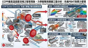
4.2 單管感應加熱確保組織均勻性與避免 AC1 極限突破 / 4.2 Ensuring Microstructural Uniformity and Avoiding Ac1 Limit Exceedance via Single-Pipe Induction Heating
傳統的大型高溫爐區(Furnace)加熱往往面臨爐膛空間溫度分佈嚴重不均的物理限制。對於動輒長達十數公尺、幾何形狀複雜的三維 3D/5D Spool 而言,極易發生管線局部加熱不足或超溫的悲劇。針對 P91/P92 這類高合金材料,最核心且不可碰觸的冶金禁忌,便是 PBHT 加熱溫度絕對不可超越其下臨界奧氏體轉變溫度(AC1)28。 Traditional large high-temperature furnace heating often faces physical constraints due to severely uneven temperature distributions within the chamber. For complex 3D/5D spools measuring tens of meters long, local under-heating or overheating tragedies easily occur. For high-alloy materials like P91/P92, the most critical and untouchable metallurgical taboo is that the PBHT heating temperature must absolutely never exceed its lower critical austenite transformation temperature (AC1)28.
AC1 溫度受鋼材微量化學成分(尤其是鎳 Ni 與錳 Mn)的影響極大。一般標準 P91 的 AC1 約在 810°C 左右,但若鋼廠出貨時 Mn+Ni 含量偏高(例如達 0.49%),AC1 可能大幅驟降至約 733°C 左右28。這與 730°C-770°C 的標準回火區間產生了致命的重疊。若 PBHT 保溫溫度不慎超過實際的 AC1,材料內部將發生局部奧氏體化,冷卻後會形成硬脆、富含內應力且毫無潛變強度的「新鮮未回火馬氏體」(Fresh Martensite),這將導致動力管線的服役壽命從設計的十萬小時,銳減至幾萬小時甚至數千小時內便發生災難性斷裂。 The AC1 temperature is highly sensitive to trace chemical compositions in the steel (especially Nickel, Ni, and Manganese, Mn). A standard P91’s AC1 is around 810°C, but if a mill delivers steel with higher Mn+Ni content (e.g., reaching 0.49%), the AC1 could plummet significantly to around 733°C28. This creates a fatal overlap with the standard 730°C-770°C tempering range. Should the PBHT soaking temperature inadvertently exceed the actual AC1, local austenitization will occur internally. Upon cooling, this forms hard, brittle “Fresh Untempered Martensite” laden with internal stresses and completely devoid of creep strength. This catastrophe would slash the power piping’s service life from the designed 100,000 hours down to mere tens of thousands or even thousands of hours before disastrous rupture strikes.
為徹底解決此痛點,現代三合一冷彎工法全面導入了單管感應加熱(Induction Heating – PBHT, IH-PBHT)技術。感應加熱利用高頻交變磁場,在管壁金屬內部直接誘發渦流(Eddy Current),實現由內而外的自發性焦耳加熱。相較於傳統輻射或傳導式加熱,感應加熱效率極高,且可針對每一件 Spool 獨一無二的三維幾何形狀,客製化纏繞水冷銅線圈。然而,對於通霄二期特厚壁的動力管線而言,感應加熱面臨著電磁學上的「趨膚效應」(Skin Effect),即高頻電流容易集中於管線外壁(OD),導致外壁溫度顯著高於內壁(ID)。為克服此物理限制,頂尖的 IH-PBHT 工法透過精確調控中頻電源的頻率與線圈間距,並在管線的內、外壁同時佈設多組高精度熱電偶(Thermocouples)建立閉環控制迴路,精準壓制內外壁溫差。此舉能確保管壁最深處完美達到 730°C 以上的回火極限值,同時確保外壁最高溫度死守在 AC1 極限溫度之下,徹底消除了局部硬度異常之隱患,確保每寸管壁組織的絕對均勻性。To thoroughly resolve this pain point, modern three-in-one cold bending methods universally incorporate Single-Pipe Induction Heating (IH-PBHT) technology. Induction heating employs high-frequency alternating magnetic fields to directly induce Eddy Currents within the pipe wall metal, achieving spontaneous inside-out Joule heating. Compared to traditional radiant or conductive heating, induction heating boasts extremely high efficiency and allows customized wrapping of water-cooled copper coils tailored to each spool’s unique 3D geometry. However, for Tongxiao Phase II’s extra-thick power piping, induction heating faces the electromagnetic “Skin Effect,” where high-frequency currents concentrate on the pipe’s outer diameter (OD), causing outer wall temperatures to be significantly higher than the inner diameter (ID). To overcome this physical limitation, top-tier IH-PBHT processes precisely tune the medium-frequency power supply and coil spacing. By deploying multiple sets of high-precision thermocouples simultaneously on the inner and outer walls to establish a closed-loop control circuit, the internal-external temperature differential is accurately suppressed. This ensures the deepest parts of the pipe wall flawlessly cross the 730°C tempering threshold, while securely anchoring the outer wall’s peak temperature below the AC1 limit. This completely eliminates risks of local hardness anomalies and guarantees the absolute uniformity of the microstructure across every inch of the pipe wall.
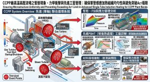
4.3 現場配管銲接與反覆修補之熱處理冶金危機 / 4.3 Metallurgical Crises from Field Piping Welding and Repeated Repair Heat Treatments
在傳統管線施工中,P91 鋼的現場對接銲縫若遭遇非破壞性檢測(NDT)未通過,將面臨極為嚴峻的反覆熱處理挑戰。這進一步突顯了「去銲接化」工法的絕對優勢。針對 P91 鋼的配管銲接,其熱處理循環可分為三個關鍵階段:In traditional piping construction, if P91 field girth welds fail Non-Destructive Testing (NDT), they face the severe challenge of repeated heat treatments. This further highlights the absolute superiority of the “Weldless” method. For P91 pipe welding, the heat treatment cycle is divided into three critical stages:
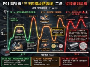
第一次的配管銲接熱處理標準循環:P91 鋼的初始銲接規範極為嚴格,銲前必須預熱至最低 200°C,且層間溫度嚴格限制不得超過 300°C,以防止氫致裂紋並控制熱梯度。銲接完成後,不能直接加熱,必須先讓銲道自然冷卻至 200°C 以下(通常為 80°C–100°C),確保微觀組織完全轉變為堅硬、充滿內應力的「新鮮馬氏體」。隨後才能進入標準的銲後熱處理(PWHT)循環,溫度通常設定在 730°C 至 770°C 之間。此循環的核心目的在於消除銲接殘留應力,並將脆硬的馬氏體轉化為具備優異高溫潛變強度的「回火板條馬氏體」,同時促使 M23C6 與碳氮化物在晶界與晶粒內均勻析出。First Standard Cycle for Pipe Welding Heat Treatment: P91 steel’s initial welding specs are incredibly strict. Preheating to a minimum of 200°C is required, and interpass temperatures are strictly capped at 300°C to prevent hydrogen-induced cracking and manage thermal gradients. Once welding is complete, immediate heating is forbidden. The weld must naturally cool below 200°C (usually 80°C–100°C) to ensure the microstructure fully transforms into hard, stress-filled “fresh martensite.” Only then can the standard Post-Weld Heat Treatment (PWHT) cycle begin, typically set between 730°C and 770°C. The core purpose is to relieve residual welding stress and convert brittle martensite into “tempered lath martensite” with excellent high-temperature creep strength, while promoting the uniform precipitation of M23C6 and carbonitrides inside grains and at boundaries.
第二次的銲道剷修研磨熱處理必要循環:若銲道在非破壞性檢測(NDT)中發現裂紋或未熔合等瑕疵,必須進行剷除、研磨並重新補銲。金屬熔融冷卻後會再次生成極脆的新鮮馬氏體與極高的局部殘留應力,因此第二次的 PWHT 是絕對強制且必要的。儘管這意味著周邊原本已經回火過的母材與舊銲道將經歷第二次的高溫保溫(增加了熱暴露時間),但只要第一次的初始熱處理參數正確,且未超過材料極限,第二次的 PWHT 通常不會對 P91 的整體力學性質與微觀組織造成毀滅性的衰退。Second Mandatory Cycle for Weld Gouging/Grinding Repair Heat Treatment: If NDT reveals flaws like cracks or lack of fusion, the weld must be gouged, ground, and re-welded. Upon cooling, the molten metal will once again form extremely brittle fresh martensite and immense local residual stress, making a second PWHT absolutely mandatory. Although this means the surrounding already-tempered base metal and old weld will endure a second high-temperature soaking (increasing thermal exposure time), as long as the initial heat treatment parameters were correct and limits were not breached, a second PWHT typically will not cause devastating degradation to P91’s overall mechanical properties or microstructure.
第三次的銲道剷修研磨熱處理冶金危機:若銲口面臨第三次剷修與 PWHT,將引發極為嚴重的「冶金危機」。P91 鋼的熱處理狀態高度依賴 Larson-Miller 參數(LMP)來評估溫度與時間的累積效應。第三次 PWHT 會使材料的「累積保溫時間」大幅超出安全極限,導致嚴重的過度回火(Over-tempering)。在微觀冶金上,這會造成原本細小且均勻分佈的 M23C6 碳化物與 MX 析出相發生嚴重的「聚集與粗化」,徹底喪失對位錯運動的釘紮效應。這將導致局部區域出現致命的「軟化區」,硬度可能跌破 185 HBW 的安全底線,其高溫潛變強度將呈現斷崖式下降,極易在服役初期發生破裂。為避免此一不可逆的冶金破壞,工程實務上面對第三次修補時,通常會直接將該段銲口完全切除,插入一段新管並重新進行第一次銲接。由此可見,採用 3D/5D 冷作彎管徹底消除現場銲口,是避開 P91 反覆修補冶金危機的最有效策略。Third Metallurgical Crisis Cycle for Repeated Repair Heat Treatment: Facing a third gouging and PWHT triggers a severe “Metallurgical Crisis.” P91’s heat treatment state relies heavily on the Larson-Miller Parameter (LMP) to evaluate the cumulative effects of time and temperature. A third PWHT pushes the material’s “cumulative soaking time” far beyond safe limits, resulting in severe over-tempering. Microscopically, this causes the originally fine, uniformly distributed M23C6 carbides and MX precipitates to undergo massive “agglomeration and coarsening,” totally losing their pinning effect on dislocation movement. This creates fatal “softened zones” locally, where hardness can plunge below the 185 HBW safety baseline. Its high-temperature creep strength plummets disastrously, making it highly prone to rupture early in service. To avoid this irreversible metallurgical destruction, engineering practice facing a third repair usually dictates cutting the entire weld out, inserting a new pipe section, and restarting with a first weld. Thus, utilizing 3D/5D cold bends to entirely eliminate field welds is the most effective strategy for bypassing P91’s repeated repair metallurgical crises.
五、 QR Code數位履歷與全壽命週期檢修應用 / 5. QR Code Digital Passports and Full Life-Cycle Maintenance Applications
通霄二期 CCPP 專案中的動力管線不僅在製造硬體與冶金技術上達到巔峰,在品質保證與全壽命週期管理(Lifecycle Management)的軟體層面上,更透過導入專屬的「QR Code 數位履歷」技術,實現了預測性維護(Predictive Maintenance)的典範轉移,將管線管理推向數位孿生(Digital Twin)的境界。The power piping in the Tongxiao Phase II CCPP project reaches the pinnacle not only in manufacturing hardware and metallurgical technology but also in software for Quality Assurance and Lifecycle Management. By introducing exclusive “QR Code Digital Passport” technology, it achieves a paradigm shift in Predictive Maintenance, propelling pipeline management into the realm of the Digital Twin.
5.1 九大品質管制點 (CP1-CP9) 之數據整合 / 5.1 Data Integration of Nine Quality Control Points (CP1-CP9)
每一支經過 3D/5D 冷彎與 IH-PBHT 處理的高能動力管線,皆被視為一個獨立的高價值航太級組件。製造廠在工廠內實施極度嚴格的九大品質管制點(CP1-CP9)檢驗,涵蓋了管線生命週期的每一個關鍵物理與冶金參數,形成完整的數據流:Every high-energy power pipe processed with 3D/5D cold bending and IH-PBHT is treated as an independent, high-value aerospace-grade component. The factory enforces an extremely rigorous nine-point quality control (CP1-CP9) inspection, encompassing every critical physical and metallurgical parameter of the pipe’s lifecycle to form a complete data stream:
在加工啟動前,首要進行材料溯源與化學成分鑑別(PMI),精確核對 Mn+Ni 當量以界定該管件獨有的 AC1 溫度界線。緊接著進行彎前幾何測量,利用超音波或雷射掃描精確量測母管的初始壁厚分佈與真圓度。進入 CNC 冷彎程序時,系統會實時記錄彎曲角度、伺服推進速度與幾何成形應變率。彎管完成後,立即進行彎後尺寸驗證,量測最終的橢圓度(確保嚴格小於 8% 甚至 3%)與局部減薄率,確保符合 ASME Barlow 方程式的 tm 要求13。隨後,管件進入最關鍵的 IH-PBHT 熱處理站,系統會自動生成並儲存完整的熱處理曲線,包含升溫速率、750°C-770°C 的恆溫保溫區間、降溫速率以及內外壁溫差熱電偶的即時數據28。熱處理完成後,品保人員會進行全面的冶金硬度檢測,涵蓋管背、管腹及中性軸的硬度分佈,確保硬度值精準落在 185-250 HV/HBW 區間,驗證 Larson-Miller 參數的完美達成。隨後,管線必須通過非破壞性檢測(NDT),包含表面磁粒探傷(MT)或液滲探傷(PT),以及探測內部體積性缺陷的超音波檢測(UT),排除任何潛在的微裂紋。最後經過表面防鏽處理與最終三維尺寸檢驗,確保 Spool 能完美對接現場安裝座標。這海量的結構力學與冶金參數,最終被雲端化並加密整合為單一的 QR Code 數位護照,直接雷射雕刻或永久附著於管線銘牌上。 Before processing begins, material traceability and Positive Material Identification (PMI) are conducted to precisely verify Mn+Ni equivalents and define the unique AC1 temperature boundary for that specific pipe. Pre-bend geometric measurements follow, using ultrasound or laser scanning to capture the parent pipe’s initial wall thickness distribution and ovality. During the CNC cold bend procedure, the system logs bending angles, servo booster speeds, and geometric forming strain rates in real time. Upon completion, post-bend dimensional verification instantly measures final ovality (ensuring it is strictly under 8% or even 3%) and local thinning rates to meet ASME Barlow equation tm requirements13. The fitting then enters the critical IH-PBHT station, where the system automatically generates and saves the complete thermal curve, including heating rates, the 750°C-770°C soak zone, cooling rates, and real-time inner-outer wall thermocouple differentials28. Post-heat treatment, QA personnel conduct comprehensive metallurgical hardness testing across the extrados, intrados, and neutral axis, ensuring hardness falls precisely within the 185-250 HV/HBW range to validate perfect Larson-Miller Parameter attainment. The pipe must then pass Non-Destructive Testing (NDT), including surface Magnetic Particle (MT) or Penetrant Testing (PT), and Ultrasonic Testing (UT) for volumetric flaws, ruling out micro-cracks. Finally, after anti-rust treatment and a 3D dimensional check to guarantee perfect field tie-in coordinates, this massive trove of structural and metallurgical data is clouded, encrypted, and integrated into a single QR Code digital passport, laser-engraved or permanently affixed to the pipe’s nameplate.
5.2 預測性維護與 FAC 監測基線 / 5.2 Predictive Maintenance and FAC Monitoring Baselines
這份獨一無二的 QR Code 數位履歷對於電廠維運團隊(O&M)具有不可估量的長遠實用價值,尤其在防範流體加速腐蝕(FAC)的厚度監測方面。在過去的傳統電廠大修中,檢修工程師常利用超音波測厚儀(UT)量測彎管外弧側厚度,一旦發現數值低於圖紙上的「公稱厚度」,往往會直接且錯誤地判定管線已經發生了嚴重的 FAC 減薄,進而草率決定切管更換。事實上,這種誤判源於忽略了冷彎工法固有的初始物理減薄(例如 5D 彎管先天即擁有約 8%~10% 的製造減薄)。This unique QR Code digital passport holds incalculable long-term practical value for plant Operations & Maintenance (O&M) teams, particularly for wall thickness monitoring to prevent Flow-Accelerated Corrosion (FAC). During traditional plant overhauls, inspection engineers frequently used Ultrasonic Thickness (UT) gauges to measure bend extrados thickness. If the value fell below the “nominal thickness” on drawings, they often incorrectly assumed severe FAC thinning had occurred, hastily deciding to cut and replace the pipe. In reality, this misjudgment stems from ignoring the inherent initial physical thinning from the cold bending process (e.g., 5D bends naturally possess ~8%–10% manufacturing thinning).
現在,透過智慧型裝置掃描 QR Code 數位護照,檢修工程師可以直接連線至雲端資料庫,讀取該特定管件在出廠時「最原始、最真實的管壁厚度三維分佈圖(Thickness Mapping)」。這個包含先天減薄數據的模型,構成了電廠預測性維護真正的 T-zero(時間零點)基線。在未來十至二十年的歷次大修中,現場測得的 UT 數據均可直接與此真實基線進行網格化比對,從而精確計算出流體沖刷所造成的「真實 FAC 磨耗速率(Wear Rate)」。結合 EPRI 的 Kastner 或 Chexal-Horowitz FAC 預測模型,維護團隊能夠極度科學且精準地評估管線的剩餘安全壽命(Remaining Useful Life, RUL)。這種數據驅動的預測性維護策略,不僅徹底避免了因人為誤判而導致的非計畫性停機與過早抽換管線的龐大財務浪費,更將電廠動力管網的運轉可靠度推向了全新的數位化高度。Now, by scanning the QR Code passport with a smart device, engineers can connect directly to the cloud database to retrieve the pipe’s “most original, authentic 3D Thickness Mapping” from when it left the factory. This model, embedding innate manufacturing thinning data, constitutes the true T-zero (time zero) baseline for the plant’s predictive maintenance. In subsequent overhauls over the next 10 to 20 years, field UT data can be gridded and compared directly against this true baseline, accurately calculating the “real FAC wear rate” driven by fluid scouring. Combined with EPRI’s Kastner or Chexal-Horowitz FAC predictive models, maintenance teams can scientifically and precisely evaluate the piping’s Remaining Useful Life (RUL). This data-driven predictive maintenance strategy completely averts the massive financial waste of unplanned outages and premature pipe replacements caused by human misjudgment, propelling the operational reliability of the plant’s power piping network to new digitized heights.
六、 P91高能管線工程實務與營運決策分析 / 6. P91 High-Energy Piping Engineering Practices and Operational Decision Analysis
除了在流體力學與材料冶金上的學術論證,通霄二期 CCPP 專案在實際工程執行與商業營運層面,亦需針對傳統 1.5D 對銲彎頭與 3D/5D 冷作彎管的差異進行綜合評估。本節將從業主營運、EPC 設計、三合一工法之「能彎不銲」核心價值合規性,以及頻繁起停下應變率放寬之應對策略等四大實務面向進行深度擴充。Beyond academic demonstrations in fluid mechanics and materials metallurgy, the Tongxiao Phase II CCPP project requires a comprehensive assessment contrasting traditional 1.5D butt-welded elbows with 3D/5D cold bends across actual engineering execution and commercial operations. This section expands deeply into four practical dimensions: owner operations, EPC design, the compliance of the “bend instead of weld” core value of the three-in-one method, and response strategies for strain rate relaxation under frequent start-stops.
6.1 CCPP廠業主之維護管理及營運決策評估 / 6.1 Maintenance Management and Operational Decision Assessment for CCPP Owners
從 CCPP 電廠業主(如台灣電力公司)的角度而言,維護管理與總體擁有成本(Total Cost of Ownership, TCO)是營運決策的核心。若採用傳統 1.5D 銲接彎頭,由於其曲率半徑小且帶有現場銲縫,在長期運轉下是流體加速腐蝕(FAC)與熱疲勞破壞的絕對熱點。這迫使業主在每次歲修大修時,必須投入高昂的檢測成本,頻繁針對彎頭進行超音波測厚(UT)與非破壞檢測。一旦發現壁厚接近極限值,便需安排緊急停機切管更換,極大增加了非計畫性停機(Unplanned Outage)的風險與營收損失。From the perspective of CCPP owners (like Taiwan Power Company), maintenance management and Total Cost of Ownership (TCO) form the core of operational decisions. If traditional 1.5D welded elbows are adopted, their small bend radii and field welds render them absolute hotspots for Flow-Accelerated Corrosion (FAC) and thermal fatigue over long-term operations. This forces owners to invest exorbitant inspection costs during every annual overhaul, frequently performing UT and NDT on elbows. Once wall thickness approaches the limit, emergency shutdowns for pipe replacement must be arranged, vastly escalating risks of unplanned outages and revenue loss.
相反地,若營運決策轉向採用 3D/5D 冷作彎管,憑藉其平滑流場與去銲接化特性,能顯著降低 FAC 磨耗速率,使管線生命週期輕鬆延長至與電廠本體相當(約 25-30 年)。雖然初期採購特製母管與冷彎加工的資本支出(CAPEX)可能微幅上升,但長期所省下的歲修檢驗費用、免除更換管件的材料與人力成本,以及提升的電廠可用率,將使得長期的營運支出(OPEX)大幅降低,為業主創造出極具經濟效益的長期回報。Conversely, if operational decisions pivot to 3D/5D cold bends, their smooth flow fields and weldless nature significantly slash FAC wear rates, easily extending the piping lifecycle to match the plant’s own (about 25-30 years). Although the initial Capital Expenditure (CAPEX) for custom parent pipes and cold bending might marginally increase, the long-term savings in overhaul inspection fees, eliminated material and labor costs for pipe replacements, and boosted plant availability will drastically lower Operational Expenditure (OPEX), generating highly economic long-term returns for the owner.
6.2 EPC承包商設計單位之空間排列與管固設計實務 / 6.2 Spatial Arrangement and Pipe Support Design Practices for EPC Contractors
對於統包商(EPC)的管線應力設計工程師而言,1.5D 彎頭與 3D/5D 彎管在空間排列與系統柔性(Flexibility)上有著截然不同的實務考量。1.5D 彎頭的幾何佔地面積最小,對於空間極度限縮的汽輪機廠房看似具備佈局優勢。然而,根據 ASME B31J 規範,1.5D 彎頭的柔性特徵值(h)極低,意味著其吸收熱膨脹的能力極差,且會產生極高的應力強化係數(SIF)。這迫使設計單位必須在管線系統中盲目增設大量昂貴的剛性管架、彈簧吊架甚至油壓阻尼器(Snubbers),以對抗高溫產生的位移應力,並防止超標的荷重(Nozzle Loads)傳遞至脆弱的高速旋轉機械(如汽輪機或壓縮機)接口上。For piping stress design engineers at EPC contractors, 1.5D elbows and 3D/5D bends present vastly different practical considerations regarding spatial arrangement and system flexibility. 1.5D elbows occupy the smallest geometric footprint, ostensibly offering a layout advantage in highly confined turbine buildings. However, per ASME B31J, the flexibility characteristic (h) of 1.5D elbows is exceedingly low, meaning their capacity to absorb thermal expansion is abysmal, generating massive SIFs. This forces designers to blindly plaster piping systems with expensive rigid supports, spring hangers, and even hydraulic snubbers to combat high-temperature displacement stresses and prevent excessive nozzle loads from transferring onto fragile high-speed rotating machinery (e.g., turbines or compressors).
若設計單位改採 3D/5D 冷作彎管,雖然大半徑會占用較大的物理轉彎空間,對佈局設計提出更高挑戰,但其柔性係數(k-factor)顯著提升。這種管線自身具備的優異彈性,能像彈簧般自然吸收高溫熱膨脹位移,大幅減少管網對膨脹彎(Expansion Loops)與重型支撐組件的依賴。這不僅簡化了鋼構支架的設計與噸數,更能有效將設備終端的噴嘴荷重壓制在安全範圍內,是現代化先進電廠設計的黃金準則。Should designers pivot to 3D/5D cold bends, the larger radii do occupy more physical turning space, posing greater layout challenges; however, their flexibility k-factor is markedly enhanced. This innate, spring-like elasticity effortlessly absorbs high-temperature thermal expansion displacements, drastically cutting the network’s reliance on expansion loops and heavy support assemblies. This not only simplifies steel structure design and reduces tonnage but also effectively suppresses equipment terminal nozzle loads within safe limits, representing the golden standard for modernized advanced plant design.
6.3 導入潁璋工程「能彎不銲」三合一工法之核心理念與 P9x 合規性實踐 / 6.3 Implementation of the Core Philosophy of Ying-Zhang Engineering’s “Bend Instead of Weld” Three-in-One Method and P9x Compliance
通霄二期 CCPP 在 3D/5D 冷管彎的應用上,若單純僅追求物理上的大半徑彎曲,將無可避免地面臨前述 P91 鋼加工硬化與 AC1 相變的冶金危機。因此,導入潁璋工程(Ying-Zhang Engineering)所提倡的「三合一工法」(3D/5D CNC 大半徑冷作彎管 + IH-PBHT 單管感應亞臨界彎後熱處理 + QR Code 雲端數位履歷),是發揮大半徑優勢的唯一解方32。此工法管理的核心價值在於徹底落實「能彎不銲」的設計理念,從源頭將易受流體沖刷與疲勞破壞的銲縫轉化為連續平滑的母材彎曲段。針對 P9x 高能管線,此工法的執行不僅是製造手段的升級,更是嚴格對接 ASME B31.1 與 B31J 規範的合規性展現。這種將製造、冶金與運維數據深度綁定的三合一模式,能為 EPC 統包商提供最可靠的品質背書,確保冷作彎管在無銲接的狀態下,依然能滿足高溫超臨界管線對於厚度、真圓度及冶金組織的極致要求,大幅降低專案整體生命週期的風險。 In Tongxiao Phase II CCPP’s application of 3D/5D cold bends, merely chasing physical large-radius curves inevitably runs into the aforementioned metallurgical crises of P91 work hardening and AC1 phase transformations. Therefore, introducing the “Three-in-One Method” championed by Ying-Zhang Engineering (3D/5D CNC large-radius cold bending + IH-PBHT single-pipe induction subcritical post-bend heat treatment + QR Code cloud digital passports) is the only solution to truly unlock the advantages of large radii32. The core management value of this method lies in thoroughly implementing the “bend instead of weld” design philosophy, transforming welds—which are highly susceptible to fluid scouring and fatigue failure—into continuous, smooth base metal bend sections right from the source. For P9x high-energy piping, the execution of this method is not only an upgrade in manufacturing techniques but also a demonstration of strict compliance with ASME B31.1 and B31J codes. This triad model—deeply binding manufacturing, metallurgical, and O&M data—provides EPC contractors with the most reliable quality endorsement. It ensures that cold bends, in a weldless state, still meet the extreme requirements of high-temperature supercritical piping regarding thickness, ovality, and metallurgical structure, thereby drastically reducing risks across the project’s entire lifecycle.
6.4 複循環機組頻繁起停下之應變率放寬 (5%~20%) 解析與 IH-PBHT 適用性 / 6.4 Analysis of Strain Rate Relaxation (5%~20%) and IH-PBHT Applicability under Frequent Start-Stops of Combined Cycle Units
在複循環燃氣機組 (CCPP) 頻繁起停的物理暫態與熱力學循環下,動力管線承受著極端的高溫潛變與低周波疲勞(Creep-Fatigue)交互破壞機制21。在冷彎成形過程中,5D 彎管的幾何成形應變率(Strain Rate)約為 10%,而 3D 彎管則高達約 16.67%12。針對這類大變形量,最新的 ASME 規範(如 2026 年版 B31.1 的演進)針對 5% 至 20% 的成形應變率區間進行了放寬與規範重構,但其先決條件是強制要求必須導入精確的彎後熱處理 (PBHT) 介入機制25。透過 IH-PBHT 單管感應加熱技術,能精準修復這 5%~20% 巨量塑性應變所造成的加工硬化與晶界損傷,釋放殘留應力並重塑 P9x 鋼的微觀析出強化網絡。這使得管線在不突破 AC1 相變極限的前提下,完全具備抵抗 CCPP 頻繁熱力循環破壞的韌性與潛變強度。透過 IH-PBHT 的精確介入,工程設計得以在法規放寬的 5%~20% 應變率區間內安全合法地採用 3D/5D 冷彎,實現了流體力學消能與冶金壽命的完美平衡。 Under the physical transients and thermodynamic cycles of frequent start-ups and shutdowns in Combined Cycle Power Plants (CCPP), power piping is subjected to extreme interactive failure mechanisms of high-temperature creep and low-cycle fatigue (Creep-Fatigue)21. During the cold bending process, the geometric forming strain rate of a 5D bend is approximately 10%, while a 3D bend reaches about 16.67%12. For such massive deformations, the latest ASME codes (such as the evolution of the 2026 edition of B31.1) have relaxed and restructured the regulations for the 5% to 20% forming strain rate range, but on the prerequisite that a precise Post-Bend Heat Treatment (PBHT) intervention mechanism is mandatorily introduced25. Through IH-PBHT single-pipe induction heating technology, the work hardening and grain boundary damage caused by this 5%~20% massive plastic strain can be precisely repaired, relieving residual stresses and reshaping the microscopic precipitation-strengthening network of P9x steel. This equips the piping with the toughness and creep strength necessary to resist the frequent thermal cyclic damage of CCPPs without breaching the AC1 phase-transformation limit. Through the precise intervention of IH-PBHT, engineering designs can safely and legally adopt 3D/5D cold bends within the code-relaxed 5%~20% strain rate range, achieving a perfect balance between fluid dynamic energy dissipation and metallurgical lifespan.
6.5 現場配管安裝與銲接實務考量 / 6.5 Practical Considerations for Field Piping Installation and Welding
在施工現場的安裝實務中,採用 1.5D 彎頭意味著必須進行大量的現場環向對接銲縫(Girth Butt Welds)。如前文所述,P91 鋼的現場銲接條件極端嚴苛:必須架設複雜的預熱設備以維持 200°C 預熱,銲工必須在狹窄且悶熱的空間內嚴格控制層間溫度不得超過 300°C,銲後還需繁瑣的保溫降溫與高達 760°C 的 PWHT 程序。在多雨或高濕度的戶外工區,這類現場銲接不僅極易發生氫致裂紋,更常因 NDT 檢驗不合格而陷入反覆剷修的「冶金危機」。此外,龐大的銲接與熱處理作業亦需要搭建大量的高空施工架,嚴重拖延工程進度。In field installation practices, utilizing 1.5D elbows means executing a massive number of field Girth Butt Welds. As previously stated, P91 steel field welding conditions are extremely severe: complex preheating equipment must be rigged to maintain 200°C; welders must strictly cap interpass temperatures at 300°C in cramped, sweltering spaces; and post-weld tasks require tedious insulated cooling followed by 760°C PWHT procedures. In rainy or high-humidity outdoor work zones, such field welds are not only highly susceptible to hydrogen-induced cracking but also frequently trap projects in “metallurgical crises” of repeated repairs due to failed NDTs. Moreover, these massive welding and heat treatment operations require erecting extensive high-altitude scaffolding, severely delaying project schedules.
相對而言,3D/5D 冷作彎管徹底貫徹了「去銲接化」與「工廠預製化(Prefabrication)」的理念。將數個方向轉折合併於一根長管中一體成形,能將現場的銲口數量削減 50% 至 70% 以上。這些預製完成並帶有 QR Code 履歷的 Spool 運抵現場後,安裝團隊僅需進行少數幾道簡單的管線對接(Tie-ins)。這大幅降低了現場施工對高階銲工技術的依賴,徹底減少了高空作業與惡劣天候的干擾,為 EPC 統包商節省了鉅額的現場勞工成本,並確保了建廠進度能如期如質達成。
By contrast, 3D/5D cold bends thoroughly embody the philosophies of “Weldless” design and “Factory Prefabrication.” Consolidating multiple directional turns seamlessly into a single long pipe can slash field weld counts by 50% to 70% or more. Once these prefabricated spools, equipped with QR Code passports, arrive on-site, the installation team only needs to perform a handful of straightforward tie-ins. This drastically lowers field reliance on top-tier welding skills, profoundly minimizes interference from high-altitude tasks and adverse weather, saves EPC contractors colossal field labor costs, and guarantees that plant construction schedules are met on time and with quality.
七、 結論 / 7. Conclusion
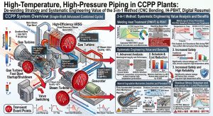
高溫高壓動力管線作為次世代複循環發電廠(CCPP)輸送能量的動脈,其初始設計與製造工法的優劣,直接決定了電廠數十年服役期間的營運效率、經濟性與絕對的生命安全。本研究以通霄二期 CCPP 更新改建專案為核心場域,深度剖析了「去銲接化」策略與「三合一工法」(即 3D/5D CNC 冷作彎管 + IH-PBHT 單管感應熱處理 + QR Code 數位履歷)的系統性工程價值。High-temperature and high-pressure power piping acts as the energy-transporting artery of next-generation Combined Cycle Power Plants (CCPP). The superiority of its initial design and manufacturing methods directly dictates the operational efficiency, economics, and absolute safety of the plant throughout decades of service. Centered around the Tongxiao Phase II CCPP Renewal and Upgrading Project, this study deeply analyzed the systemic engineering value of the “Weldless” strategy and the “Three-in-One Method” (i.e., 3D/5D CNC Cold Bending + IH-PBHT Single-Pipe Induction Heating + QR Code Digital Passports).
從流體力學的微觀視角而言,5D 冷作彎管透過提供平滑連續的曲率過渡並徹底消除環向銲縫,消解了管內因幾何突變所引發的強烈迪恩渦流(Dean Vortices)與流體分離現象,將質量傳遞係數(MTC)降至最低,從物理化學的根源上強力抑制了流體加速腐蝕(FAC)的發生,並極大地緩衝了蒸汽水錘的破壞動能。在結構力學層面,該工法透過 CNC 機台的高精度幾何控制,將橢圓度與減薄率壓制在極限範圍內,完美呼應了 ASME B31J 最新規範中針對應力強化係數(SIF)三維解耦計算與柔性特徵值(h)的嚴格要求,徹底消除了傳統 1.5D 短彎頭在潛變-疲勞交互作用下的應力集中熱點。From a micro-fluid dynamics perspective, 5D cold bends—by providing smooth, continuous curvature transitions and completely eliminating girth welds—dissolve intense Dean Vortices and flow separation induced by geometric discontinuities. This minimizes the Mass Transfer Coefficient (MTC), powerfully suppressing Flow-Accelerated Corrosion (FAC) from its physico-chemical roots and vastly buffering the destructive kinetic energy of steam hammers. On a structural mechanics level, this method employs high-precision CNC geometric control to suppress ovality and thinning within limits. This perfectly aligns with the latest ASME B31J code’s strict requirements for 3D decoupled SIF calculations and flexibility characteristics (h), completely eradicating stress concentration hotspots inherent to traditional 1.5D short elbows under creep-fatigue interaction.
更進一步,透過精密閉環調控的 IH-PBHT 感應加熱技術,精確繞開了 P91/P92 高合金鋼極度敏感的 AC1 相變極限溫度,完美重塑了材料的高溫抗潛變微觀組織,消除了冷作硬化的隱患,並徹底避免了現場銲道反覆修補所帶來的冶金危機。最終結合涵蓋九大品質管制點的 QR Code 數位履歷,為電廠維運團隊提供了無懈可擊的 FAC 監測 T-zero 數據基石。綜上所述,此一完美整合了流固耦合優化、前瞻冶金強化與數位孿生概念的三合一工法,強而有力地向 EPC 統包商與業界證明:大半徑冷彎技術早已超越單純的安裝便利性,更是為高效率燃氣電廠築起極致安全性與長效運轉經濟性的不可或缺的關鍵解決方案。Furthermore, through precision closed-loop controlled IH-PBHT induction heating, the process accurately circumvents the highly sensitive AC1 phase-change limit temperature of P91/P92 high-alloy steels. It flawlessly reshapes the material’s high-temperature creep-resistant microstructure, neutralizes work hardening hazards, and totally bypasses the metallurgical crises wrought by repeated field weld repairs. Finally, coupled with QR Code digital passports encompassing nine quality control points, it grants plant O&M teams an impeccable T-zero data cornerstone for FAC monitoring. In summary, this three-in-one method—perfectly integrating fluid-structure interaction optimization, forward-looking metallurgical strengthening, and Digital Twin concepts—potently proves to EPC contractors and the industry that large-radius cold bending technology has long surpassed mere installation convenience. It is an indispensable, critical solution for constructing ultimate safety and long-term operational economics in high-efficiency gas-fired power plants.
參考文獻 / References
- 通霄電廠更新改建進環評供氣管路線須與風電商溝通 – 焦點事件, https://eventsinfocus.org/news/7146033
- Glossary of Abbreviations and Acronyms, https://www-pub.iaea.org/MTCD/DSS/OASISGlossary.pdf?3gaFVh=Rr0fE
- Flow Accelerated Corrosion in Nuclear Power Plants – IntechOpen, https://www.intechopen.com/chapters/39784
- Light Water Reactor Sustainability Program Flow-Assisted Corrosion, https://inldigitallibrary.inl.gov/content/uploads/50/2026/04/Sort_8784.pdf
- Flow-Accelerated Corrosion – The Entrance Effect – EPRI, https://restservice.epri.com/publicdownload/000000000001015072/0/Product
- Effect of Dissolved Oxygen on Flow-Accelerated Corrosion in, https://eurocorr.org/Archive/EUROCORR+2017/EFC+Awards+and+Prizes/_/EUROCORR2017-Paper78701-Fujiwara.pdf
- FAC Calculation Model Overview | PDF | Corrosion | Density – Scribd, https://www.scribd.com/document/570299980/65-FAC-Calculation-model-engels
- CFD-BASED INVESTIGATION OF TURBULENT FLOW BEHAVIOR, https://polipapers.upv.es/index.php/JARTE/article/download/20665/16464
- 1 s2.0 S2590123025049825 Main | PDF | Viscosity | Computational, https://www.scribd.com/document/998242496/1-s2-0-S2590123025049825-main
- (PDF) Study of accelerated erosion of elbow-shaped connections, https://www.researchgate.net/publication/372633409_Study_of_accelerated_erosion_of_elbow-shaped_connections_with_corrosion_defects
- Numerical investigation of Dean vortex evolution in turbulent flow, https://www.frontiersin.org/journals/mechanical-engineering/articles/10.3389/fmech.2025.1405148/full
- 2026 ASME B31J 規範下冷作彎管曲率半徑(R值)選用準則與實務應用, https://yz-pipe-bending.com.tw/%E9%AB%98%E9%BB%8F%E5%BA%A6%E9%9D%9E%E7%89%9B%E9%A0%93%E6%B5%81%E9%AB%94%E7%AE%A1%E7%B7%9A%E8%BC%B8%E9%80%81%E4%B9%8B%E6%B5%81%E5%9B%BA%E8%80%A6%E5%90%88%E8%88%87%E5%8A%9B%E5%AD%B8%E6%9C%80%E4%BD%B3/
- 基於ASME B31J (2024-2026) 規範演進之高能管線佈局最佳化, https://yz-pipe-bending.com.tw/%E5%9F%BA%E6%96%BC-asme-b31j-2024-2026-%E8%A6%8F%E7%AF%84%E6%BC%94%E9%80%B2%E4%B9%8B%E9%AB%98%E8%83%BD%E7%AE%A1%E7%B7%9A%E4%BD%88%E5%B1%80%E6%9C%80%E4%BD%B3%E5%8C%96%EF%BC%9A3d-5d-%E5%86%B7%E4%BD%9C/
- Mastering ASME B31J Piping Stress Analysis for Plant Integrity, https://epcland.com/asme-b31j-piping-stress-analysis/
- Stress Intensification Factors (SIFs) in Pipe Stress Analysis, https://simumech.com/stress-intensification-factors-sifs-in-pipe-stress-analysis/
- Understanding Stress Intensification Factor | PDF – Scribd, https://www.scribd.com/document/961304245/Stress-Intensification-Factor
- ASME B31.1-2024 Stress Intensification Factors (SIFs) — FAQ, https://pipingtoolset.com/faq/b311-stress-intensification-factors/
- Stress Intensity Factor (SIF), Flexibility Factor: ASME B31.3 vs ASME, https://whatispiping.com/stress-intensity-factor-sif-flexibility-factor-asme-b-31j/
- Stress Intensification Factor (SIF)| Pipie Stress Analysis, https://www.universalengineeringconsultants.com/post/stress-intensification-factor-sif-and-its-impact
- 基於2026 ASME B31J 規範之CCPP 高能管線銲接彎頭與3D/5D 冷作, https://yz-pipe-bending.com.tw/%E5%9F%BA%E6%96%BC-2026-asme-b31j-%E8%A6%8F%E7%AF%84%E4%B9%8B-ccpp-%E9%AB%98%E8%83%BD%E7%AE%A1%E7%B7%9A%E9%8A%B2%E6%8E%A5%E5%BD%8E%E9%A0%AD%E8%88%87-3d-5d-%E5%86%B7%E4%BD%9C%E5%BD%8E%E7%AE%A1%E7%B5%90/
- Recommendation for Creep and Creep-fatigue assessment for P91, https://publications.jrc.ec.europa.eu/repository/bitstream/JRC94508/jrc94508_matter_4-6_creep-fatigue.pdf
- CCPP管線工程中設計使用SR & LR 套銲彎頭與3D、5D 冷作彎管對於, https://yz-pipe-bending.com.tw/ccpp%E7%AE%A1%E7%B7%9A%E5%B7%A5%E7%A8%8B%E4%B8%AD%E8%A8%AD%E8%A8%88%E4%BD%BF%E7%94%A8-sr-lr-%E5%A5%97%E9%8A%B2%E5%BD%8E%E9%A0%AD%E8%88%87-3d%E3%80%815d-%E5%86%B7%E4%BD%9C%E5%BD%8E%E7%AE%A1%E5%B0%8D/
- An LES study of secondary motion and wall shear stresses in a pipe, https://www.osti.gov/biblio/1833836
- Pipe Bend Wall Thickness Calculator — ASME B31.3 ¶304.2.1, https://pipingtoolset.com/calculators/pipe-bend-wall-thickness/
- 2026 ASME 規範下1 動力管線施工工法之深度剖析, https://yz-pipe-bending.com.tw/2026-asme-%E8%A6%8F%E7%AF%84%E4%B8%8B-b31-1-%E5%8B%95%E5%8A%9B%E7%AE%A1%E7%B7%9A%E6%96%BD%E5%B7%A5%E5%B7%A5%E6%B3%95%E4%B9%8B%E6%B7%B1%E5%BA%A6%E5%89%96%E6%9E%90%EF%BC%9A5d-%E5%86%B7%E4%BD%9C%E5%BD%8E/
- 基於ASME B31J 規範之電廠高能管線預製工法最佳化, https://yz-pipe-bending.com.tw/%E5%9F%BA%E6%96%BC-asme-b31j-%E8%A6%8F%E7%AF%84%E4%B9%8B%E9%9B%BB%E5%BB%A0%E9%AB%98%E8%83%BD%E7%AE%A1%E7%B7%9A%E9%A0%90%E8%A3%BD%E5%B7%A5%E6%B3%95%E6%9C%80%E4%BD%B3%E5%8C%96%EF%BC%9A%E5%A4%A7%E5%8D%8A/
- 現代高能動力管線「以彎代銲」之技術經濟評估:從傳統配管到大, https://yz-pipe-bending.com.tw/%E7%8F%BE%E4%BB%A3%E9%AB%98%E8%83%BD%E5%8B%95%E5%8A%9B%E7%AE%A1%E7%B7%9A%E3%80%8C%E4%BB%A5%E5%BD%8E%E4%BB%A3%E9%8A%B2%E3%80%8D%E4%B9%8B%E6%8A%80%E8%A1%93%E7%B6%93%E6%BF%9F%E8%A9%95%E4%BC%B0%EF%BC%9A/
- https://yz-pipe-bending.com.tw/astm-a335-p91-%E5%90%88%E9%87%91%E9%8B%BC%E4%B9%8B%E5%9B%9E%E7%81%AB%E5%8B%95%E5%8A%9B%E5%AD%B8%E3%80%81larson-miller-%E5%8F%83%E6%95%B8%E8%88%87%E7%86%B1%E8%99%95%E7%90%86%E5%B7%A5%E6%B3%95%E6%B7%B1/
- P91 Steel Welding — Preheat 200°C, Interpass ≤300°C … – tempil.vn, https://tempil.vn/en/blog/p91-steel-welding-temperature/
- 超超临界机组耐热钢焊接技术进展, https://hj.hwi.com.cn/cn/article/pdf/preview/10.12073/j.hj.20231228001.pdf
- P91 Normalization and Tempering Guide | PDF | Heat Treating | Steel, https://www.scribd.com/document/323997387/Normalization-and-Temper-Heat-Treatment-on-P91
- 解析2026 ASME B31.1與B31J應變率(5%~20%)放寬與IH-PBHT適用, https://yz-pipe-bending.com.tw/%E8%A7%A3%E6%9E%902026-asme-b31-1%E8%88%87b31j%E6%87%89%E8%AE%8A%E7%8E%87520%E6%94%BE%E5%AF%AC%E8%88%87ih-pbht%E9%81%A9%E7%94%A8%EF%BC%9A%E6%BD%81%E7%92%8B%E5%B7%A5%E7%A8%8B%E5%B0%8D%E6%96%BCp9x/