
一、 緒論與研究背景 / 1. Introduction and Research Background
在現代超臨界(Supercritical)與超超臨界(Ultra-Supercritical, USC)火力發電廠以及先進石化工業中,高壓蒸汽管線與集管等核心壓力部件的材料選擇,對於整體機組的熱效率與運行壽命具有決定性的影響。P91(9Cr-1Mo-V-Nb)鋼作為一種典型的潛變強度強化鐵素體鋼(Creep Strength Enhanced Ferritic Steel, CSEF),憑藉其優異的高溫潛變抗力、極佳的抗氧化腐蝕性能以及較低的熱膨脹係數,已成為運作溫度介於 550°C 至 600°C 區間之關鍵部件的首選材料1。In modern supercritical (SC) and ultra-supercritical (USC) thermal power plants and advanced petrochemical industries, the material selection for core pressure components, such as high-pressure steam piping and headers, plays a decisive role in the overall thermal efficiency and service life of the unit. P91 (9Cr-1Mo-V-Nb) steel, a typical creep strength enhanced ferritic (CSEF) steel, has become the material of choice for critical components operating in the 550°C to 600°C temperature range due to its exceptional high-temperature creep resistance, excellent oxidation and corrosion resistance, and low thermal expansion coefficient1。
P91 鋼的高溫機械性能,深植於其複雜且高度階層化的微觀組織。該組織主要由回火麻田散鐵基底構成,內部蘊含極高密度的差排網絡,並透過分佈於原沃斯田鐵晶界(PAGB)與馬氏體板條晶界上的富鉻 M₂₃C₆ 碳化物,以及均勻散佈於晶粒內部的奈米級富釩/鈮 MX 型碳氮化物,共同發揮顯著的固溶強化與析出釘扎效應1。The high-temperature mechanical properties of P91 steel are deeply rooted in its complex and highly hierarchical microstructure. This structure is primarily composed of a tempered martensite matrix containing a remarkably high density of dislocation networks. It leverages solid-solution strengthening and precipitation pinning effects provided by Cr-rich M₂₃C₆ carbides distributed along prior austenite grain boundaries (PAGBs) and martensite lath boundaries, as well as nanoscale V/Nb-rich MX-type carbonitrides uniformly dispersed within the grains1。
然而,在發電廠長達數萬小時的高溫高應力服役過程中,部件不可避免地會因局部潛變損傷、熱疲勞或原始製造瑕疵,而面臨局部補銲修復的需求5。由於 P91 鋼本身具有極高的空冷硬化傾向,銲接熱循環會在熱影響區(HAZ)與銲道金屬中產生堅硬且極脆的未回火麻田散鐵,同時伴隨極高的殘留應力。為此,國際法規(如 ASME B31.1)與美國電力研究所(EPRI)指南皆強制要求,P91 鋼的銲接必須實施嚴格的銲後熱處理(PWHT)1。However, during tens of thousands of hours of high-temperature and high-stress service in power plants, components inevitably require local repair welding due to localized creep damage, thermal fatigue, or original manufacturing defects5。Because P91 steel possesses an extremely high air-hardening tendency, the welding thermal cycle generates hard and brittle untempered martensite in the heat-affected zone (HAZ) and weld metal, accompanied by high residual stresses. Consequently, international codes (such as ASME B31.1) and Electric Power Research Institute (EPRI) guidelines strictly mandate that post-weld heat treatment (PWHT) be performed on P91 steel welds1。
當針對曾經歷過初始製造 PWHT 以及長期高溫服役的組件進行局部補銲時,原銲道與相鄰的母材將被迫承受「第二次」的熱處理循環。業界標準程序的「二次四階段熱處理」涵蓋了預熱、高溫除氫烘烤、受控降溫相變以及最終的高溫回火。此一極端的高溫熱暴露,若在降溫相變階段控制不當,或在二次高溫回火時累積了過量的 Larson-Miller 參數(LMP),將對原本已趨於熱力學亞穩態的微觀組織造成毀滅性的破壞。本研究報告旨在深度剖析二次熱處理如何驅動析出相加速粗化與 Laves 相吞噬效應,並探討這些微觀退化如何最終導致高溫潛變強度的致命性衰退,進而誘發危害極大的 Type IV 潛變裂痕機制。When performing local repair welding on components that have already undergone initial manufacturing PWHT and long-term high-temperature service, the original weld bead and adjacent base metal are forced to endure a “secondary” heat treatment cycle. The industry-standard “secondary four-stage heat treatment” involves preheating, high-temperature hydrogen bake-out, controlled cooling for phase transformation, and final high-temperature tempering. If this extreme thermal exposure is improperly controlled during the cooling phase transformation, or if an excessive Larson-Miller Parameter (LMP) accumulates during secondary tempering, it will cause devastating damage to the previously metastable microstructure. This report systematically analyzes how secondary heat treatment drives accelerated precipitate coarsening and Laves phase engulfment, and explores how these microscopic degradations lead to a fatal decline in high-temperature creep strength, ultimately inducing the highly hazardous Type IV creep cracking mechanism.

二、 P91鋼局部補銲之二次四階段熱處理冶金學機制 / 2. Metallurgical Mechanisms of Secondary Four-Stage Heat Treatment for P91 Steel Repair Welding
2.1 P91鋼之熱力學相變與臨界溫度界定 / Thermodynamic Phase Transformations and Critical Temperatures
P91 鋼的合金設計高度依賴精確的相變控制,以獲得完全的麻田散鐵組織。在探討二次熱處理的影響前,必須首先釐清該鋼種的熱力學臨界溫度。P91 鋼的下臨界轉變溫度(AC1)與上臨界轉變溫度(AC3)受其化學成分的強烈影響,特別是沃斯田鐵穩定元素(如 Ni、Mn)與鐵素體穩定元素(如 Cr、Mo)的比例7。The alloy design of P91 steel relies heavily on precise phase transformation control to achieve a fully martensitic structure. Before discussing the effects of secondary heat treatment, the thermodynamic critical temperatures of this steel must be clarified. The lower critical transformation temperature (AC1) and upper critical transformation temperature (AC3) are strongly influenced by its chemical composition, particularly the ratio of austenite-stabilizing elements (like Ni, Mn) to ferrite-stabilizing elements (like Cr, Mo)7。
實驗數據顯示,P91 鋼的 AC1 溫度通常介於 785°C 至 830°C 之間,而 AC3溫度則落於 891°C 至 941°C 的範圍。在冷卻過程中,沃斯田鐵轉變為麻田散鐵的起始溫度(Ms)約為 339°C 至 400°C,而確保相變完全終止的溫度(Mf)則極低,通常介於 96°C 至 150°C 之間1。相較於傳統低合金鋼,P91 的臨界冷卻速率極低,這使得其在銲接後皆無可避免地形成硬脆馬氏體7。在二次補銲情境下,銲材通常會刻意提高 Ni 與 Mn 的含量;然而 Ni 與 Mn 每增加 1%,皆會顯著壓低 AC1 溫度,導致銲道金屬的 AC1 可能下探至 760°C 邊緣,極大地壓縮了後續 PWHT 的安全操作極限值1。Experimental data show that the AC1 temperature of P91 steel typically ranges between 785°C and 830°C, while AC1 falls within 891°C to 941°C. During cooling, the martensite start temperature (Ms) is about 339°C to 400°C, and the martensite finish temperature (Mf) is extremely low, generally between 96°C and 150°C1。Compared to traditional low-alloy steels, P91 has a very low critical cooling rate, making the formation of hard and brittle martensite inevitable after welding7。In repair welding scenarios, filler metals often intentionally increase Ni and Mn contents; however, each 1% increase in Ni and Mn significantly lowers the AC1 temperature. This can push the AC1 of the weld metal down to the 760°C margin, drastically compressing the safe operating limits for subsequent PWHT1。
| 臨界溫度參數 / Critical Temp Parameters | 典型數值範圍 / Typical Range | 影響因素與冶金學意義 / Influencing Factors & Metallurgical Significance |
| 下臨界溫度 (Ac1) / Lower Critical Temp | 785°C – 830°C | 銲材中 Ni+Mn 若超過 1.0%,AC1 顯著下降。PWHT 絕不可超越此極限值。 / Ac1 drops significantly if Ni+Mn > 1.0% in filler. PWHT must never exceed this limit.1 |
| 上臨界溫度 (Ac3) / Upper Critical Temp | 891°C – 941°C | 決定母材正火處理的最低溫度。 / Determines the minimum temperature for base metal normalizing. |
| 麻田散鐵起始溫度 (Ms) / Martensite Start | 339°C – 400°C | 決定銲接預熱與層間溫度的上限。 / Determines the upper limit for preheat and interpass temperatures. |
| 麻田散鐵終止溫度 (Mf) / Martensite Finish | 96°C – 150°C | 銲後必須冷卻至此溫度以下,確保相變完全。 / Weld must cool below this to ensure complete phase transformation.1 |
2.2 二次四階段熱處理之標準程序與操作風險 / Standard Procedures and Operational Risks of Secondary Four-Stage Heat Treatment
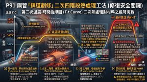
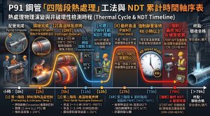
業界發展出嚴密的「四階段熱處理」工法以安全修復 P91 鋼。第一階段為「銲前預熱與層間溫度控制」,規範明訂壁厚超過 13 mm 的管線最低預熱溫度需達 204°C,層間溫度不超過 350°C1。第二階段為「高溫除氫烘烤」,銲接完成後必須立即加熱至 300°C 至 350°C 並保溫 2 至 3 小時,以驅趕游離氫避免冷裂紋1。The industry has developed a rigorous “four-stage heat treatment” method to safely repair P91 steel. The first stage is “Preheat and Interpass Temperature Control,” where codes mandate a minimum preheat of 204°C for piping thicker than 13 mm, with interpass temperatures not exceeding 350°C1。The second stage is the “High-Temperature Hydrogen Bake-Out,” where the weld must immediately be heated to 300°C–350°C and held for 2–3 hours to drive out diffusible hydrogen and prevent cold cracking1。
第三階段為「相變控制冷卻」,必須讓組件緩慢冷卻至 Mf 溫度以下(強烈建議降至 96°C 以下)1。若因趕工導致內部未降至 Mf 以下便啟動加熱,將引發相變災難:殘留沃斯田鐵會在後續降至室溫時轉變為「新鮮且未經回火的麻田散鐵」,導致局部硬度飆升至 400 HV 以上,成為脆斷根源11。第四階段為「最終高溫 PWHT」,將組件加熱至 740°C 至 760°C 進行深度回火1。然而,重複的高溫保溫將引發析出相極度粗化,這正是構成材料潛變抗力瓦解的核心風險1。The third stage is “Phase Transformation Controlled Cooling,” requiring the component to cool slowly below the Mf temperature (strongly recommended below 96°C)1。If heating is initiated before the core drops below Mf due to rushed schedules, a phase transformation disaster will occur: retained austenite will transform into “fresh untempered martensite” upon final cooling to room temperature, causing local hardness to spike above 400 HV and triggering brittle fracture11。The fourth stage is the “Final High-Temperature PWHT,” heating the component to 740°C–760°C for deep tempering1。However, repeated high-temperature soaking induces extreme precipitate coarsening, which constitutes the core risk of creep resistance collapse1。
三、 P91鋼三階熱處理循環之累積退化歷程 / 3. Cumulative Degradation History of P91 Steel over Three Heat Treatment Cycles
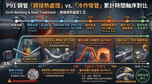
為了具體理解上述冶金機制在實務中的影響,本章將從宏觀的工程時間軸出發,依次深度剖析 P91 鋼在經歷第一次標準循環、第二次必要修復,乃至第三次災難性再剷修時的累積退化歷程。To concretely understand the impact of the aforementioned metallurgical mechanisms in practice, this chapter outlines the cumulative degradation history of P91 steel sequentially from a macroscopic engineering timeline, covering the first standard cycle, the second necessary repair cycle, and the catastrophic third re-grinding cycle.
3.1 第一次的配管銲接四階段熱處理標準循環 / First Standard Four-Stage Heat Treatment Cycle for Pipe Welding
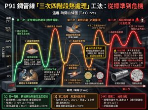
在新建電廠的管線安裝階段,P91 鋼的初始銲接必須嚴格遵守第一次的四階段配管銲接熱處理標準循環。這是一個極度嚴苛的工法: 第一階段為「銲前預熱與層間溫度控制」,必須施加至少 204°C 的預熱,並在銲接全程將層間溫度控制在 350°C 以下1。 第二階段為「高溫除氫烘烤」,銲接完成後嚴禁直接冷卻,接頭必須立即被加熱至 300°C 至 350°C 之間,並持續保溫 2 至 3 小時。這能讓殘存於厚壁銲道內的擴散氫獲得足夠的能量迅速逸散,從根本上防範破壞性的氫致冷裂紋1。 第三階段為至關重要的「相變控制冷卻」,除氫完成後,接頭必須包裹保溫棉緩慢冷卻至麻田散鐵終止溫度(Mf,低於 96°C,強烈建議降至 90°C 以下)。這個步驟是確保原本高溫狀態下的奧氏體能夠 100% 轉變為麻田散鐵,避免殘留奧氏體在後續引發脆化1。 第四階段為「最終的高溫銲後熱處理(PWHT)」,將溫度平緩提升至 740°C 至 760°C 進行深度回火。這能有效釋放銲接收縮帶來的殘餘應力,並促進細小的 M₂₃C₆ 與 MX 碳氮化物均勻析出。此標準循環完成後,接頭硬度將完美落在 180 HV 至 265 HV 的安全區間,具備最佳的初始潛變抗力1。During the piping installation phase of a new power plant, the initial welding of P91 steel must strictly adhere to the first standard four-stage pipe welding heat treatment cycle. This is an extremely rigorous method: The first stage is “Preheat and Interpass Temperature Control,” applying a minimum preheat of 204°C and strictly keeping the interpass temperature below 350°C throughout the process1. The second stage is “High-Temperature Hydrogen Bake-Out.” Direct cooling after welding is strictly prohibited; the joint must immediately be heated to 300°C–350°C and held for 2 to 3 hours. This allows the diffusible hydrogen trapped within the thick-walled weld to gain sufficient energy and rapidly diffuse out, fundamentally preventing destructive hydrogen-induced cold cracking1. The third stage is the critical “Phase Transformation Controlled Cooling.” After the bake-out, the joint must be wrapped in insulation and slowly cooled below the martensite finish temperature (Mf, below 96°C, highly recommended below 90°C). This step ensures that the high-temperature austenite transforms 100% into martensite, preventing retained austenite from causing future embrittlement1. The fourth stage is the “Final High-Temperature PWHT,” raising the temperature smoothly to 740°C–760°C for deep tempering. This effectively relieves welding-induced residual stresses and promotes the uniform precipitation of fine M₂₃C₆ and MX carbonitrides. After completing this standard cycle, the joint hardness perfectly lands within the safe range of 180 HV to 265 HV, providing optimal initial creep resistance1.
3.2 第二次的剷修研磨四階段熱處理必要循環 / Second Necessary Four-Stage Heat Treatment Cycle for Grinding and Repair
在非破壞檢測(NDE)發現製造瑕疵或經歷初期服役損傷後,管線必須進行剷修研磨與重新補銲,迫使母材與熱影響區承受第二次的四階段熱處理必要循環。在此修復循環中,工程人員同樣必須完整且精確地執行上述的預熱、除氫烘烤、降溫相變以及高溫 PWHT 四大步驟1。After non-destructive examination (NDE) reveals manufacturing defects or early service damage, the piping must undergo grinding, repair, and re-welding, forcing the base metal and heat-affected zone to endure a second necessary four-stage heat treatment cycle. During this repair cycle, engineers must fully and precisely execute the aforementioned four steps: preheating, hydrogen bake-out, cooling phase transformation, and high-temperature PWHT1.
然而,實務上這個第二次循環隱藏著極大的邊界風險。為了維持修復區銲金屬的衝擊韌性,修復銲材常添加較高的鎳(Ni)與錳(Mn),這會導致銲道的下臨界溫度(AC1)顯著下降(可能逼近 760°C),極大壓縮了第四階段二次 PWHT 的安全操作極限值1。更重要的是,這第二次的長時間高溫回火促使 Larson-Miller 參數(LMP)開始疊加累積15。原本在第一次循環中穩定釘扎的 M₂₃C₆ 碳化物,會因為獲得過剩的熱能而依循 Ostwald 熟化機制開始粗化,Zener 釘扎力初步下滑,導致差排網絡開始回復8。儘管宏觀結構尚未完全崩解,但相間熱影響區(ICHAZ)的硬度已明顯下探,逼近 EPRI 規範的 180 HV 安全紅線邊緣1。However, in practice, this second cycle harbors significant boundary risks. To maintain the impact toughness of the repair weld metal, repair fillers often contain higher Nickel (Ni) and Manganese (Mn). This significantly lowers the lower critical temperature (AC1) of the weld bead (potentially approaching 760°C), drastically compressing the safe operating limit for the fourth stage’s secondary PWHT1. More importantly, this second prolonged high-temperature temper forces the Larson-Miller Parameter (LMP) to accumulate15. The M₂₃C₆ carbides, originally stably pinning boundaries during the first cycle, gain excess thermal energy and begin to coarsen via the Ostwald ripening mechanism. This causes an initial drop in the Zener pinning force and leads to the recovery of dislocation networks8. Although the macroscopic structure has not completely collapsed, the hardness of the intercritical heat-affected zone (ICHAZ) drops noticeably, dangerously approaching the edge of the EPRI 180 HV safety red line1.
3.3 第三次的再剷修研磨四階段熱處理冶金危機 / Third Metallurgical Crisis of Four-Stage Heat Treatment for Re-grinding and Repair
若因檢測再度不合格或管線發生早期的 Type IV 裂紋而被迫進行第三次剷修與重新補銲,P91 鋼將被迫承受第三次的四階段熱處理,這將引發一場無可挽回的「冶金危機」。在此階段,雖然前三階的預熱、烘烤與相變皆可照常執行,但在進入第四階段的 PWHT 時,前三次高溫保溫所累積的總 LMP 將嚴重突破材料的熱力學容忍極限。If forced into a third grinding, repair, and re-welding due to repeated inspection failures or early Type IV cracking, P91 steel endures a third four-stage heat treatment, triggering an irreversible “metallurgical crisis.” At this stage, while the first three stages (preheat, bake-out, and phase transformation) can be executed as usual, entering the fourth stage’s PWHT pushes the total accumulated LMP from three high-temperature soaks severely beyond the material’s thermodynamic tolerance limit.
這極端超標的熱暴露將驅動毀滅性的微觀退化。受矽(Si)偏析強烈驅動的 Laves 相(Fe₂Mo/W)會大量成核,並以驚人的速率吞噬那些已經嚴重粗化的 M₂₃C₆ 碳化物,將基底中的固溶強化元素鉬(Mo)消耗殆盡18。完全失去碳化物的釘扎保護後,改良型 Williamson-Hall (MWH) 分析證實差排發生了大規模的湮滅,次晶粒急遽膨脹合併14。巨觀上,ICHAZ 區域的硬度將無可挽回地跌破 160 HV,徹底喪失機械強度1。在這種極度軟弱的組織下,高局部潛變應變率會誘發強烈的晶界滑移(GBS),引爆海量潛變空穴成核,最終在極短的服役時間內撕裂出致命的 Type IV 裂痕29。這標誌著常規的四階段熱處理修復工法已徹底失效。This extremely excessive thermal exposure drives devastating microstructural degradation. Strongly driven by Silicon (Si) segregation, the Laves phase (Fe₂Mo/W) nucleates massively and engulfs the already severely coarsened M₂₃C₆ carbides at an alarming rate, completely depleting the matrix of its solid-solution strengthening element, Molybdenum (Mo)18. Completely stripped of carbide pinning protection, Modified Williamson-Hall (MWH) analysis confirms massive large-scale dislocation annihilation and rapid subgrain expansion and coalescence14. Macroscopically, the hardness of the ICHAZ region irreversibly plummets below 160 HV, completely losing its mechanical strength1. In this extremely weakened structure, high local creep strain rates induce severe grain boundary sliding (GBS), triggering the nucleation of massive creep cavities, which ultimately tear open fatal Type IV cracks in a very short service timeframe29. This signifies the absolute failure of the conventional four-stage heat treatment repair method.
四、 析出相動力學與微觀組織退化機制 / 4. Precipitate Kinetics and Microstructural Degradation Mechanisms
為了徹底釐清上述三階段循環中導致材料退化甚至崩解的物理本質,本章將深入探討高溫熱暴露下析出相的動力學演變,以及其對微觀組織的深遠影響。To fully elucidate the fundamental physics behind the material degradation and collapse described in these three cycles, this chapter delves into the kinetic evolution of precipitates under high-temperature thermal exposure and their profound impact on the microstructure.
4.1 M₂₃C₆ 與 MX 析出相之 Ostwald 熟化理論 / Ostwald Ripening Theory of M₂₃C₆ and MX Precipitates
P91 鋼會沿著 PAGB 與次晶界析出富鉻的 M₂₃C₆ 碳化物(約 100-150 奈米),並在板條內部均勻析出細小的富釩/鈮 MX 碳氮化物(約 20-50 奈米)19。M₂₃C₆ 提供強大的 Zener 釘扎力以抑制晶界遷移;而 MX 則阻擋差排滑移2。P91 steel precipitates Cr-rich M₂₃C₆ carbides (approx. 100-150 nm) along PAGBs and subgrain boundaries, and uniformly precipitates fine V/Nb-rich MX carbonitrides (approx. 20-50 nm) within laths19。M₂₃C₆ provides strong Zener pinning force to inhibit grain boundary migration, while MX blocks dislocation slip2。
在二次與三次熱處理中,析出相演化遵循 LSW 理論中的 Ostwald 熟化模型,其動力學方程為:r–3-r03=Kt。模擬與量測表明,M₂₃C₆ 的粗化速率常數 K 遠大於 MX17。在 760°C 的高溫下,擴散係數呈指數級上升,導致 M₂₃C₆ 迅速膨脹至 300 奈米甚至 600 奈米以上18。隨著半徑急劇增大,Zener 釘扎力斷崖式下降,導致次晶界獲得遷移自由度18。During secondary and tertiary heat treatments, precipitate evolution follows the Ostwald ripening model in LSW theory, with the kinetic equation: r–3-r03=Kt . Simulations and measurements indicate that the coarsening rate constant K of M₂₃C₆ is far greater than that of MX17。Under the high temperature of 760°C, the diffusion coefficient rises exponentially, causing M₂₃C₆ to rapidly expand to 300 nm or even over 600 nm18。As the radius sharply increases, the Zener pinning force drops precipitously, granting subgrain boundaries the freedom to migrate18。
4.2 Laves 介金屬相之析出與矽偏析驅動之吞噬機制 / Laves Phase Precipitation and Silicon Segregation-Driven Engulfment
累積的熱能會誘發 Laves 相(Fe₂Mo/W)析出。TEM 分析證實,Laves 相展現出極高的異質成核傾向,主要於既有的粗大 M₂₃C₆ 與鐵素體基底的相交界面處成核21。此現象源於矽(Si)原子向該介面擴散偏析,顯著降低了 Laves 相的成核能壘。The accumulated thermal energy induces Laves phase (Fe₂Mo/W) precipitation. TEM analysis confirms that the Laves phase exhibits a strong tendency to nucleate heterogeneously at the interfaces between existing coarse M₂₃C₆ carbides and the ferrite matrix21。This is driven by the segregation of silicon (Si) atoms to these interfaces, which significantly lowers the Laves phase nucleation energy barrier.
一旦 Laves 相成核,會展現極高的生長速率,不斷抽取鉬(Mo)原子,並逐漸溶解吞噬相鄰的 M₂₃C₆21。這種「吞噬」造成雙重破壞:一是消耗固溶強化元素 Mo,導致基底弱化4;二是晶界釘扎物轉變為間距極寬的 Laves 顆粒,為次晶粒粗化敞開大門24。Once nucleated, the Laves phase exhibits a very high growth rate, continuously extracting molybdenum (Mo) atoms and gradually dissolving and engulfing adjacent M₂₃C₆21。This “engulfment” causes dual damage: first, it consumes the solid-solution strengthening element Mo, weakening the matrix4;second, grain boundary pinning agents transition into widely spaced Laves particles, opening the door for subgrain coarsening24。
4.3 差排密度湮滅與次晶粒成長之 Modified Williamson-Hall 分析 / Modified Williamson-Hall Analysis of Dislocation Annihilation and Subgrain Growth
運用 X 射線繞射結合 Modified Williamson-Hall (MWH) 分析,可量化金屬內部的差排密度14。當實施 760°C 的二次或三次 PWHT 時,熱能賦予差排足夠動能進行攀緣與滑移,導致異號差排相互湮滅27。當 M₂₃C₆ 失去釘扎力時,次晶界發生大尺度遷移與合併,平均尺寸會從約 0.3 微米膨脹至超過 1 微米39。Using X-ray diffraction combined with Modified Williamson-Hall (MWH) analysis, internal dislocation densities can be quantified14。When a 760°C secondary or tertiary PWHT is applied, thermal energy gives dislocations sufficient kinetic energy to climb and slip, causing dislocations of opposite signs to annihilate each other27。As M₂₃C₆ loses its pinning force, subgrain boundaries undergo large-scale migration and coalescence, inflating the average size from roughly 0.3 μm to over 1 μm39。
五、 硬度劣化與 Larson-Miller 參數之交互驗證 / 5. Hardness Degradation and Larson-Miller Parameter Cross-Validation
前述微觀組織的退化,將直接反映在巨觀的機械性質劣化上。實務中,工程師通常透過計算熱暴露參數並輔以現場硬度測試,來驗證管線剩餘壽命的衰退程度。The aforementioned microstructural changes directly manifest as macroscopic mechanical degradation. In practice, engineers commonly calculate thermal exposure parameters supplemented by on-site hardness testing to verify the extent of the pipeline’s remaining life deterioration.
5.1 Larson-Miller 參數 (LMP) 累積效應 / Accumulated Larson-Miller Parameter (LMP) Effects
熱處理的綜合影響常以 Larson-Miller 參數(LMP)量化:LMP=T×(C+logt )×10-3,常數 C 對 9% 鉻鋼通常取 20 15。原母材已累積了出廠與初次 PWHT 的熱暴露,若疊加二次或三次 PWHT,總 LMP 將飆升至危險水準16。高 LMP 驅動下的 M₂₃C₆ 粗化與差排湮滅是不可逆的必然結果49。The combined effects of heat treatment are typically quantified using the Larson-Miller Parameter (LMP): LMP=T×(C+logt )×10-3, where the constant C is usually 20 for 9% Cr steels15。The base metal has already accumulated thermal exposure from manufacturing and the initial PWHT; superimposing a secondary or tertiary PWHT spikes the total LMP to dangerous levels16。M₂₃C₆ coarsening and dislocation annihilation driven by high LMP are irreversible, inevitable outcomes49。
5.2 硬度指標與 EPRI 安全紅線 / Hardness Indicators and EPRI Safety Red Line
P91 鋼理想硬度應落在 180 HV 至 265 HV 之間1。然而,當重複的 PWHT 導致過度回火時,硬度將急遽下滑。EPRI 劃定之安全紅線為 180 HV,低於此極限值標誌著微觀結構已崩壞1。在不當或多次熱處理案例中,相間熱影響區(ICHAZ)硬度甚至下探至 160 HV 以下1。The ideal hardness of P91 steel should fall between 180 HV and 265 HV1。However, when repeated PWHT causes over-tempering, hardness drops precipitously. EPRI designates a safety red line at 180 HV; dropping below this threshold signals that the microstructure has collapsed1。In cases of improper or multiple heat treatments, intercritical heat-affected zone (ICHAZ) hardness has even plummeted below 160 HV1。
5.3 銲接強度折減係數 (WSRF) 失效 / Failure of Weld Strength Reduction Factor (WSRF)
ASME 規範引入 WSRF 來彌補銲接接頭的潛變弱勢6。在 593°C 以上區間,WSRF 下修至 0.5 6。然而,破壞性的熱處理循環會使局部真實 WSRF 遠低於 0.5 1,導致管線壁厚餘裕耗盡,觸發第三階段潛變加速。ASME codes introduce the WSRF to compensate for the creep weakness of welded joints6。In the >593°C range, the WSRF is reduced to 0.5 6。However, destructive heat treatment cycles can push the actual local WSRF far below 0.5 1, exhausting piping wall thickness margins and triggering tertiary creep acceleration.
六、 高溫潛變空穴演化與 Type IV 裂痕誘發機制 / 6. Creep Cavity Evolution and Type IV Cracking Mechanisms
隨著硬度衰退與 WSRF 的防線瓦解,材料在高溫應力下最終將迎來致命的斷裂模式——Type IV 潛變裂痕。As hardness deteriorates and the protective margin of the WSRF collapses, the material ultimately succumbs to a fatal fracture mode under high-temperature stress: Type IV creep cracking.
歷經冶金危機後,最典型的災難是在 HAZ 外緣爆發 Type IV 潛變裂痕,往往無預警導致爆管8。在 ICHAZ 雙相區,M₂₃C₆ 僅部分溶解,經過重複 PWHT 後,Ostwald 熟化異常活躍18,形成顯著的極軟區8。Following a metallurgical crisis, the most typical catastrophic failure is Type IV creep cracking at the outer edge of the HAZ, often causing unexpected tube bursts8。In the ICHAZ two-phase region, M₂₃C₆ only partially dissolves; after repeated PWHT, Ostwald ripening becomes hyperactive18, forming a distinct ultra-soft zone8。
極軟區的高局部潛變應變率(ε•)驅動了劇烈的晶界滑移(GBS)29。物理冶金模型指出,晶界滑移是觸發空穴成核的核心,其速率與應變率成正比:n•cav=Bs ε•29。空穴膨脹縮小了承載截面積,形成正回饋災難迴圈,最終撕裂出致命的 Type IV 裂痕2。The high local creep strain rate (ε•) in the ultra-soft zone drives severe grain boundary sliding (GBS)29。Physical metallurgy models state that GBS is the core trigger for cavity nucleation, with the nucleation rate proportional to the strain rate: n•cav=Bs ε• 29。Cavity expansion reduces the load-bearing cross-section, creating a positive feedback disaster loop that ultimately tears open fatal Type IV cracks2。
七、 修復策略探討:免銲後熱處理 (Temper Bead) 技術 / 7. Repair Strategies: Temper Bead Welding (Repair Without PWHT)
為規避由二次或多次 PWHT 帶來的 Type IV 裂痕風險,工程界在面臨必須修復的管線時,開始轉向尋求「免銲後熱處理」的替代工法。To circumvent the risk of Type IV cracking brought about by secondary or multiple PWHTs, the engineering community has begun turning to alternative “repair without PWHT” methods when pipeline repairs are mandatory.
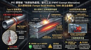
鑒於重複 PWHT 的毀滅性風險,業界積極探索以回火銲珠技術(Temper Bead Welding)為核心的修復方案5。該工法利用後層銲道的熱循環充當前層 HAZ 的局部回火5。工程上常改用鎳基銲材以消除冷裂紋風險並緩解殘留應力61。透過精確設定銲條直徑,能深入前層達到約 700°C 的微觀精煉,免除整件進爐的風險12。儘管存在異種金屬膨脹疲勞疑慮,但此方法能主動迴避 Type IV 破裂風險,具備極高工程價值10。Given the devastating risks of repeated PWHT, the industry actively explores repair solutions centered around Temper Bead Welding5。This method utilizes the thermal cycles of subsequent weld layers to act as localized tempering for the underlying HAZ5。Nickel-based filler metals are often used to eliminate cold cracking risks and alleviate residual stresses61。By precisely configuring electrode diameters, the heat penetrates the previous layer to achieve microstructural refinement around 700°C, eliminating the need to furnace-treat the whole component12。Despite concerns regarding dissimilar metal expansion fatigue, this method actively avoids Type IV fracture risks, providing tremendous engineering value10。
八、 CCPP廠 P91/P92 中小尺寸高能管線工程實務 / 8. Engineering Practices for Small and Medium-Sized High-Energy P91/P92 Piping in CCPP Plants
除了在管線受損後被動採取免熱處理的修復工法,現代電廠設計更傾向於「主動防禦」。藉由結構與幾何的改良,從源頭徹底消除銲接熱循環帶來的不確定性。本章將針對 CCPP 廠內中小尺寸高能管線,深度探討採用 1.5D 對銲彎頭與 3D/5D 冷作彎管的實務差異與決策考量。Beyond passively adopting repair-without-PWHT methods after a pipeline is damaged, modern power plant design leans towards “active defense.” By improving structural geometry, the uncertainties associated with welding thermal cycles can be thoroughly eliminated at the source. This chapter will deeply explore the practical differences and decision-making considerations between using 1.5D butt-welded elbows and 3D/5D cold bends for small and medium-sized high-energy piping in CCPP plants.
8.1 業主維護管理與營運決策 / Owner’s Maintenance Management and Operational Decision-Making
對於電廠業主而言,高能管線的生命週期成本與可用率是營運核心。採用傳統 1.5D 對銲彎頭,意味著管網中存在大量的銲道與熱影響區。在 CCPP 頻繁起停的調峰運行下,這些銲道極易誘發 Type IV 潛變裂痕與疲勞破壞。這不僅大幅增加了營運期間的非破壞檢測(NDE)成本與停機時間,更提高了無預警爆管的風險6。相反地,若業主在建廠初期決策採用 3D/5D 冷作彎管,消除了致命的環向銲道,將大幅延長管線免維護週期,降低全壽命週期成本(LCC),確保機組高調峰負載下的極致可靠度。For power plant owners, the life-cycle cost and availability of high-energy piping are core to operations. Using traditional 1.5D butt-welded elbows means a massive number of welds and heat-affected zones exist in the piping network. Under the frequent start-stop peak-shaving operations of CCPP, these welds are highly susceptible to Type IV creep cracking and fatigue failure. This not only drastically increases non-destructive examination (NDE) costs and downtime during operation but also elevates the risk of unannounced tube bursts6. Conversely, if owners mandate 3D/5D cold bends in the early stages of plant construction, eliminating the fatal circumferential welds, the maintenance-free period of the piping will be significantly extended. This lowers the Life Cycle Cost (LCC) and ensures supreme reliability under high peak-shaving loads.
8.2 EPC承包商設計單位之空間排列與實務考量 / EPC Contractor Design Unit’s Spatial Arrangement and Practical Considerations
從 EPC 設計單位的視角出發,中小尺寸高能管線在汽輪機房等侷限空間內的佈置極具挑戰。1.5D 彎頭雖然幾何體積最小、轉向最緊湊,但會帶來高達 3.0-5.0 的應力放大效應(SIF),迫使設計端必須增加額外的彈簧吊架或減震器來吸收系統應力63。若導入 3D/5D 彎管,雖然轉向半徑較大,需要設計端在 3D 建模(如 PDMS/SP3D)時預留較多緩衝空間,但能將 SIF 降至趨近於 1.0 的安全極限值。這不僅簡化了整體管網的應力分佈,更減少了昂貴的管道支撐系統數量,最終達成整體空間與力學配置的最佳化。From the perspective of EPC design units, routing small and medium-sized high-energy piping within confined spaces like turbine halls is highly challenging. Although 1.5D elbows offer the smallest geometric volume and tightest directional changes, they introduce a Stress Intensification Factor (SIF) of up to 3.0-5.0. This forces designers to add extra spring hangers or snubbers to absorb system stresses63. If 3D/5D bends are introduced, despite the larger bending radius requiring designers to allocate more buffer space during 3D modeling (e.g., PDMS/SP3D), the SIF drops close to the safe limit of 1.0. This not only simplifies the stress distribution of the entire piping network but also reduces the number of expensive pipe support systems, ultimately achieving an optimized balance of spatial and mechanical configuration.
8.3 潁璋工程三合一工法之導入與合規性 / Implementation and Compliance of the Yingzhang Engineering 3-in-1 Method
針對上述挑戰,導入「潁璋工程三合一工法」展現了極大的工程效益。該工法管理核心價值在於優化並落實「以冷作彎管導入設計(能彎不銲)」之理念,將材料特性、應力分析與先進彎管製造有機結合。在 3D 與 5D 彎管的選擇上,5D 冷作彎管是工程經濟學的最佳平衡點:其 8% 的壁厚減薄補償絕大多數可由市售標準 Schedule 鋼管的固有裕度吸收,無需耗費巨資特製超厚母管13。相較之下,3D 彎管因減薄率高達 25%,材料成本劇增13。就法規合規性而言,潁璋工程之冷作彎管三合一工法完全契合 ASME B31.1 與 B31J 規範精神,透過精確的幾何控制將應力放大效應(SIF)降至趨近 1.0 的安全極限值,從根本上消除了流動加速腐蝕(FAC)與應力腐蝕開裂,提供了一次到位的高能管線解決方案63。Addressing these challenges, adopting the “Yingzhang Engineering 3-in-1 Method” yields immense engineering benefits. The core value of this method lies in optimizing and implementing the design philosophy of “bend rather than weld” using cold bends, organically integrating material properties, stress analysis, and advanced pipe bending manufacturing. Between 3D and 5D bends, the 5D cold bend serves as the optimal balance for engineering economics: its 8% wall thinning compensation can mostly be absorbed by the inherent margins of commercial standard Schedule pipes, avoiding the exorbitant cost of custom extra-heavy parent pipes13. In contrast, 3D bends experience up to 25% thinning, causing material costs to spike13. Regarding regulatory compliance, Yingzhang Engineering’s 3-in-1 method for cold bends fully aligns with the spirit of ASME B31.1 and B31J codes. By utilizing precise geometric control to reduce the Stress Intensification Factor (SIF) close to the safe limit of 1.0, it fundamentally eliminates flow-accelerated corrosion (FAC) and stress corrosion cracking, providing a comprehensive, done-in-one high-energy piping solution63.
8.4 現場安裝 1.5D 對銲彎頭對比 3D/5D 冷作彎管實務考量 / On-site Installation Practical Considerations: 1.5D Butt-Welded Elbows vs. 3D/5D Cold Bends
在 CCPP 建廠現場的高空與惡劣氣候環境下,現場銲接 1.5D 彎頭是施工風險最高的環節。銲接人員必須在侷限空間內精確執行高達 204°C 的預熱、防護氫致裂紋的 300°C 烘烤,以及嚴苛的冷卻與 PWHT,且極易發生錯邊(High-low)超出 1.6 mm 容許值的組裝誤差1。反之,採用工廠預製的 3D/5D 冷作彎管(能彎不銲),大幅減少了現場環向銲口的數量,將剩餘的銲接點推移至平緩易操作的直管區。這不僅將現場熱處理失敗的風險降至最低,更使無損檢測(NDE)的楔塊貼合與探傷變得極為容易,大幅提升了現場安裝的安全性與施工效率。Under the high-altitude and harsh weather conditions of a CCPP construction site, field welding of 1.5D elbows is the highest-risk phase of construction. Welders must precisely execute a 204°C preheat, a 300°C hydrogen bake-out to prevent cracking, and rigorous cooling and PWHT within confined spaces. Furthermore, it is highly prone to alignment mismatch (high-low) exceeding the 1.6 mm allowable tolerance1. Conversely, using factory-prefabricated 3D/5D cold bends (“bend rather than weld”) drastically reduces the number of field circumferential welds, shifting the remaining weld joints to smooth, easily accessible straight pipe sections. This not only minimizes the risk of field heat treatment failures but also makes the coupling and scanning of non-destructive examination (NDE) wedges exceptionally easy, vastly improving on-site installation safety and construction efficiency.
8.5 複循環燃氣機組頻繁起停下之抗疲勞機制與 5%~20% 應變率之 IH-PBHT 適用性 / 8.5 Fatigue Resistance Mechanism under Frequent CCPP Start-Stops and Applicability of IH-PBHT for 5%-20% Strain Rates
現代 CCPP 燃氣發電廠肩負極端調峰任務,頻繁的起停(Start-up/Shut-down)帶來劇烈的物理瞬態熱震盪與熱力學循環,極易在管線系統中誘發潛變-疲勞交互作用(Creep-Fatigue Interaction, CFI)。在彎管加工中,成型應變率的計算公式為ϵ=ro/R1 ×100% 。若採用 5D 彎管,其最大外弧應變率約為 10%,完美落在 5% 至 20% 的最佳容許區間內13。Modern CCPP gas-fired power plants are tasked with extreme peak-shaving duties. Frequent start-ups and shut-downs introduce severe physical transient thermal shocks and thermodynamic cycles, easily inducing Creep-Fatigue Interaction (CFI) within the piping system. In pipe bending, the forming strain rate is calculated by the formula ϵ=ro/R1 ×100%. If a 5D bend is used, its maximum extrados strain rate is approximately 10%, perfectly falling within the optimal allowable range of 5% to 20%13.
依據 ASME B31.1 與 Code Case 183 等規範,對於 P91/P92 材料,當冷作彎管的局部應變率超過 20%(或高溫設計下超過 25%)時,強制要求進行整件的正常化與回火(N&T),這在實務上往往極難執行64。然而,對於應變率介於 5% 至 20% 之間的 5D 彎管,規範允許放寬並適用次臨界彎後熱處理(Subcritical PBHT,通常落於 705°C 至 760°C 區間)64。在此區間下,導入精密的局部感應加熱(Induction Heating, IH)進行 PBHT,能在絕對不逾越AC1溫度的前提下,精準提供足夠的熱活化能64。這使得晶格內因冷作變形而堆積的差排能夠進行攀緣與多邊形化,既不破壞 P9x 鋼原有的 M₂₃C₆ 與 MX 奈米強化析出相,又能徹底釋放冷作殘餘應力。這種針對 5%~20% 應變率放寬並最佳化 IH-PBHT 的操作,從微觀冶金與宏觀力學雙管齊下,賦予了 P91/P92 管線極致的抗 CFI 疲勞韌性,確保機組在長期調峰營運下的絕對安全極限值。According to codes such as ASME B31.1 and Code Case 183, for P91/P92 materials, when the local strain rate of a cold bend exceeds 20% (or 25% under high-temperature design), full Normalizing and Tempering (N&T) of the entire component is strictly mandated, which is often extremely difficult to execute in practice64. However, for a 5D bend with a strain rate between 5% and 20%, the code allows relaxation and the application of subcritical post-bend heat treatment (Subcritical PBHT, typically ranging from 705°C to 760°C)64. In this range, introducing precise local Induction Heating (IH) for PBHT provides exactly enough thermal activation energy without ever exceeding the AC1 temperature64. This enables the dislocations piled up in the lattice due to cold working to climb and polygonize, completely releasing cold-work residual stresses without destroying the original M₂₃C₆ and MX nanoscale strengthening precipitates of the P9x steel. This optimized IH-PBHT operation, tailored for the relaxed 5%-20% strain rate, addresses both micro-metallurgy and macro-mechanics simultaneously. It endows P91/P92 piping with ultimate CFI fatigue toughness, guaranteeing the absolute safety limits of the unit under long-term peak-shaving operations.
九、 結論與工程建議 / 9. Conclusions and Engineering Recommendations
- 熱力學與製程參數控制之絕對性: 銲接與熱處理的成敗嚴格繫於臨界溫度的精準掌握。銲後除氫烘烤完畢,必須確實冷卻至麻田散鐵相變終止溫度(Mf,強烈建議低於 96°C)以下,否則殘留沃斯田鐵將在 PWHT 後轉變為極脆的新鮮麻田散鐵1。同時,PWHT 溫度絕不可超越AC1下臨界點(若銲材 Ni+Mn 含量超過2%,PWHT 上限需低於 AC1 至少 10°C),並需嚴格遵守每 25 mm 壁厚保溫 1 小時的標準,避免材料進入雙相區導致組織崩解1。Absolute Control of Thermodynamics and Process Parameters: The success of welding and heat treatment depends strictly on precise temperature control. After the hydrogen bake-out, the weld must cool completely below the martensite finish temperature (Mf, strongly recommended below 96°C). Otherwise, retained austenite will transform into brittle fresh martensite after PWHT1. Furthermore, the PWHT temperature must never exceed the AC1 lower critical point (if Ni+Mn > 1.2%, the maximum PWHT must be at least 10°C below AC1), and a soak time of 1 hour per 25 mm of thickness must be strictly followed to prevent the material from entering the two-phase region and suffering microstructural collapse1.
- 三階循環之累積退化: 第一次標準循環能確保 180-265 HV 的最佳強度;第二次研磨補銲循環迫使 LMP 疊加,M₂₃C₆ 啟動粗化;一旦進入第三次再剷修循環,便會觸發不可逆的「冶金危機」。過剩的 LMP 將驅動 Laves 相成核並吞噬 M₂₃C₆,消耗鉬(Mo)元素。此微觀退化導致 Zener 釘扎力崩潰與次晶粒急遽粗化,硬度跌破 180 HV 安全紅線1 。Cumulative Degradation of the Three-Stage Cycle: The first standard cycle ensures optimal strength of 180-265 HV; the second grinding and repair cycle forces LMP accumulation, initiating M₂₃C₆ coarsening; once entering the third repair cycle, an irreversible “metallurgical crisis” is triggered. Excessive LMP drives the Laves phase to nucleate and engulf M₂₃C₆, consuming Molybdenum (Mo). This microstructural degradation collapses Zener pinning and rapidly coarsens subgrains, crashing the hardness below the 180 HV safety red line1.
- Type IV 潛變空穴之災難性成核機制: 經歷多次不當熱處理後,相間熱影響區(ICHAZ)會形成致命的極軟區。該區域的高局部潛變應變率(ε)驅動了劇烈的晶界滑移(GBS),引發極高的局部拉伸應力31。依據物理冶金模型(n•cav=Bs ε•),這將誘發海量微米級潛變空穴成核與擴散成長30。此一正回饋破壞迴圈最終將撕裂出 Type IV 潛變裂痕,使得 ASME 規範為管線設計所賦予的 0.5 銲接強度折減係數(WSRF)失去實質防護意義6。Catastrophic Nucleation Mechanism of Type IV Creep Cavities: Following multiple improper heat treatments, a fatal ultra-soft zone forms in the intercritical heat-affected zone (ICHAZ). The high local creep strain rate (ε•) in this region drives severe grain boundary sliding (GBS), inducing extremely high local tensile stresses31. According to physical metallurgy models (n•cav=Bs ε•), this induces the nucleation and diffusional growth of massive micron-scale creep cavities30. This positive feedback destruction loop ultimately tears open Type IV creep cracks, rendering the 0.5 Weld Strength Reduction Factor (WSRF) assigned by ASME codes for piping design practically meaningless6.
- 免銲後熱處理 (Temper Bead) 替代策略之權衡: 面對三次 PWHT 帶來的必然冶金危機,若修復條件允許,應優先考慮回火銲珠技術(Temper Bead Welding)。透過採用面心立方(FCC)晶格的鎳基銲材(如 ERNiCrMo-3)可有效消除氫致冷裂紋風險並吸收殘留應力61。配合精密控制前兩層銲條直徑(如5 mm 與 4.0 mm),利用後層熱傳導深入前層 HAZ 達成約 700°C 的微觀精煉,從而完全迴避將母材再次暴露於高溫爐的致命風險,是延長高能部件剩餘壽命的高工程價值方案12。Trade-offs of Alternative Repair Without PWHT (Temper Bead): Facing the inevitable metallurgical crisis brought by a third PWHT, Temper Bead Welding should be prioritized if repair conditions allow. Utilizing nickel-based consumables (e.g., ERNiCrMo-3) with a face-centered cubic (FCC) lattice effectively eliminates hydrogen cold cracking risks and absorbs residual stresses61. By precisely controlling the electrode diameters of the first two layers (e.g., 2.5 mm and 4.0 mm), the heat conduction from the subsequent layer penetrates the underlying HAZ to achieve microstructural refinement at around 700°C. This completely avoids the fatal risk of exposing the base metal to a high-temperature furnace again, making it a highly valuable engineering solution to extend the remaining life of high-energy components12.
- 管線設計「以彎代銲」之根本防護與最佳化: 針對新建或替換管線,應全面淘汰高應力放大效應(SIF)且易誘發流動加速腐蝕(FAC)的5D 傳統銲接彎頭。導入工廠預製的 5D 大半徑冷作彎管,其僅需 8% 的壁厚減薄補償,多數可由標準鋼管裕度吸收,達成極佳的工程經濟效益。更重要的是,將成型應變率精準控制在 5% 至 20% 區間,並於工廠受控環境實施次臨界彎後熱處理(PBHT,705°C – 760°C),能在完全保留 M₂₃C₆ 與 MX 奈米強化網絡的前提下釋放殘餘應力。此舉從幾何與冶金雙重層面徹底拔除了 Type IV 裂痕與應力腐蝕之隱患,確保 CCPP 機組長期運轉的安全極限值64。Fundamental Protection and Optimization through ‘Bending Instead of Welding’ in Piping Design: For new construction or piping replacements, traditional 1.5D welded elbows—which have high stress intensification factors (SIF) and induce flow-accelerated corrosion (FAC)—should be entirely phased out. Implementing factory-prefabricated 5D large-radius cold bends requires only an 8% wall thinning compensation, which is easily absorbed by standard pipe margins, achieving excellent engineering economics. Most importantly, by precisely controlling the forming strain within the 5% to 20% range and executing subcritical post-bend heat treatment (PBHT, 705°C–760°C) in a controlled factory environment, residual stresses are relieved while fully preserving the M₂₃C₆ and MX nanoscale strengthening networks. This thoroughly eradicates Type IV cracking and stress corrosion hazards on both geometric and metallurgical fronts, ensuring the safety limits for the long-term operation of CCPP units64.

參考文獻 / References
- Welding P91 Steel: Essential Requirements – WeldFabWorld, https://www.weldfabworld.com/p91-material-requirement/
- P91 Tube Repair Procedure Guide | PDF | Welding – Scribd, https://www.scribd.com/document/704159614/28-SEL-MMD-BLR-tube-repair-SMP-28
- Creep-resistant aeroengine shaft steels: precipitates and, https://brearley.msm.cam.ac.uk/2019/aeroengine_Huang_MST_2019.pdf
- Heat Resistant Steels – Page 1000 – IspatGuru, https://www.ispatguru.com/heat-resistant-steels/1000/
- Weld repair of grade 91 piping and components in power generation, https://www.researchgate.net/publication/281170067_Weld_repair_of_grade_91_piping_and_components_in_power_generation_applications_creep_performance_of_repair_welds
- What is the ASME B31.1 Power Piping Code and What is New?, https://epcland.com/asme-b31-1-power-piping-code/
- Best Practices for P91 Welding | PDF | Steel | Construction – Scribd, https://www.scribd.com/document/818702437/P91-Best-Practices
- P91 Normalization and Tempering Guide | PDF | Heat Treating | Steel, https://www.scribd.com/document/323997387/Normalization-and-Temper-Heat-Treatment-on-P91
- Metrode Consumables Catalog – ManualLib, https://www.manuallib.com/download/named/39/metrode-a-10-datasheet.pdf
- Soudabilité – Metallurgie P91- X10CrMoVNb 9-1 | PDF | Welding, https://www.scribd.com/document/1069252604/Soudabilite-Metallurgie-P91-X10CrMoVNb-9-1
- Creep Strength in Ferritic Steel Welds | PDF | Steel | Construction, https://www.scribd.com/document/606776051/03-PHASE-TRANSFORMATIONS-IN-CREEP-STRENGTH-ENHANCED-FERRITIC-STEEL-WELDS
- Grade 91 (P91) Welding and Type IV Cracking | DoaWise, https://doawise.com/blog/grade-91-p91-welding-and-type-iv-cracking/
- PHASE TRANSFORMATIONS IN CREEP STRENGTH ENHANCED, https://mtmcongress.com/proceedngs/2011/2/03.PHASE%20TRANSFORMATIONS%20IN%20CREEP%20STRENGTH%20ENHANCED%20FERRITIC%20STEEL%20WELDS.pdf
- Heat Treatment of Steels – MDPI, https://mdpi-res.com/bookfiles/book/4644/Heat_Treatment_of_Steels.pdf?v=1790816948
- Use of 9Cr-1Mo-V (Grade 91) Steel in the Oil Refining and, https://eballotprodstorage.blob.core.windows.net/eballotscontainer/API%20TR%20938-B_2n%20ed.%20draft%20_Rev.13.pdf
- Simulation Heat Treatment Requirement as per ASME, https://www.weldfabworld.com/simulation-heat-treatment/
- Type IV Cracking in 9-12%Cr Steels Review | PDF | Fracture – Scribd, https://www.scribd.com/document/275315273/Review-of-Type-IV-Cracking-of-Weldments-in-9
- P92 Steel Weldments: PWHT Effects | PDF | Heat Treating – Scribd, https://www.scribd.com/document/506581383/Caracterizacion-de-Soldaduras-de-Acero-P92-en-Condiciones-Como-Soldado-y-PWHT
- EPRI – Best Practice Guidelines For Manufacturing and Construction, https://www.scribd.com/document/412726426/EPRI-Best-Practice-Guidelines-for-Manufacturing-and-Construction-of-Grade-91-9Cr-1Mo-Steel-Components
- Grade 91 Steel Cracking Issues and Solutions | PDF – Scribd, https://www.scribd.com/document/144867388/P91-in-Service-Experience
- Evolution of microstructure and mechanical properties of the heat, https://tugraz.elsevierpure.com/ws/portalfiles/portal/1706234/Dissertation_Mayr_complete_small.pdf
- (PDF) Effect of Long-Term Aging on the Microstructural Evolution in, https://www.researchgate.net/publication/359961715_Effect_of_Long-Term_Aging_on_the_Microstructural_Evolution_in_a_P91_Steel
- The New Italian Standard on the Life Assessment of Martensitic, https://www.mdpi.com/2673-8023/3/1/20
- Thermal Ageing Effects on P92 Steel | PDF – Scribd, https://www.scribd.com/document/974653369/10-1515-htmp-2016-0040
- Roles of δ-ferrite and Laves-phase evolution in strength stability of, https://www.researchgate.net/publication/414860611_Roles_of_d-ferrite_and_Laves-phase_evolution_in_strength_stability_of_Si-enriched_dual-phase_heat-resistant_steel_aged_at_550C_for_up_to_15000_h
- (a) Standard Williamson-Hall plots for Fe peaks at different applied, https://www.researchgate.net/figure/a-Standard-Williamson-Hall-plots-for-Fe-peaks-at-different-applied-tensile-strains_fig3_259158548
- Microstructurally Based Modeling of Creep Deformation and, https://www.intechopen.com/chapters/81465
- Life Management and Maintenance – Baltica | PDF – Scribd, https://www.scribd.com/document/66537570/Life-Management-and-Maintenance-Baltica
- Your Paper’s Title Starts Here: – University of Huddersfield Repository, https://eprints.hud.ac.uk/id/eprint/21819/1/Wuhan-2013_Final.pdf
- Prediction of creep ductility for austenitic stainless steels and copper, https://www.tandfonline.com/doi/pdf/10.1080/09603409.2022.2039497
- Prediction of creep ductility for austenitic stainless steels and copper, https://www.tandfonline.com/doi/full/10.1080/09603409.2022.2039497
- Typical Type IV failure of the crosssectional weld after creep test., https://www.researchgate.net/figure/Typical-Type-IV-failure-of-the-cross-sectional-weld-after-creep-test-A-Macro-structure_fig4_288840159
- Prediction of TTR Diagrams via Physically Based Creep Simulations, https://www.scientific.net/MSF.1105.159.pdf
- Computer simulation of precipitation kinetics in solid metals and, https://www.matcalc.at/images/stories/publications/phd_thesis_rajek_2005.pdf
- Identification of Precipitates in Weldments Performed in an ASTM, https://www.researchgate.net/publication/281225476_Identification_of_Precipitates_in_Weldments_Performed_in_an_ASTM_A335_Gr_P91_Steel_by_the_FCAW_Process
- Effect of Long-Term Thermal Aging on Microstructure Evolution and, https://www.mdpi.com/1996-1944/15/10/3659
- Long-Term Steam Oxidation and Microstructural Evolution of … – MDPI, https://www.mdpi.com/1996-1944/19/12/2514
- Effect of Long-Term Aging on the Microstructural Evolution in a P91, https://pmc.ncbi.nlm.nih.gov/articles/PMC9030032/
- Creep cavities and carbide evolution in interrupted creep conditions, https://pure.port.ac.uk/ws/portalfiles/portal/97282853/Creep_cavities_and_carbide_evolution_in_interrupted_creep_conditions_along_P91_steel_of_dissimilar_weld_joint.pdf
- Coarsening behaviour of M23C6 carbides in creep-resistant steel, https://pmc.ncbi.nlm.nih.gov/articles/PMC4942832/
- Influence of welding process on Type IV cracking behavior of P91 steel, https://eprints.nmlindia.org/id/eprint/7112/
- Strengthening mechanisms of reduced activation ferritic/martensitic, http://ijmmm.ustb.edu.cn/cn/article/pdf/preview/10.1007/s12613-020-2121-1.pdf
- EPPEI – Eighth Student Workshop, https://www.eppei.co.za/wordpress/wp-content/uploads/2021/11/EPPEI-Abstracts-Booklet-2021.pdf
- Indira Gandhi Centre for Atomic Research – Kalpakkam – IGCAR, https://www.igcar.gov.in/publications/igc_annual_report_2023.pdf
- ICAS 2022: Advanced Steel Innovations | PDF – Scribd, https://www.scribd.com/document/722620675/abstract-ICAS-all220916
- Impact of Various Creep–Fatigue Interaction Loading Waveforms at, https://d-nb.info/1366862783/34
- E911/X11CrMoWVNb9-1-1(T911/P911)seamless steel pipe, https://www.pipeun.com/e911t911-p911seamless-steel-pipe/
- What is the Larson-Miller parameter? – TWI Global, https://www.twi-global.com/technical-knowledge/faqs/faq-what-is-the-larson-miller-parameter/
- Guide To Post Weld Heat Treatment: When It’s Mandatory … – Artizono, https://artizono.com/comprehensive-guide-to-post-weld-heat-treatment-pwht-requirements/
- CREEP STRENGTH EVALUATION OF SERVICED AND, http://materialsperformanceanalysis.com/wp-content/uploads/2016/09/T91-CREEP-STRENGTH-EVALUATION-OF-SERVICED.pdf
- Microstructural Study of Welded and Repair Welded Dissimilar, https://www.mdpi.com/2673-4591/119/1/9
- EPRI 3002001465 – Grade 91 Steel Handbook – Scribd, https://www.scribd.com/document/689638950/EPRI-3002001465-Grade-91-Steel-Handbook
- Stress Relaxation Cracking of Alloys at Temperatures Higher Than, https://docs.nlr.gov/docs/fy24osti/80404.pdf
- Type IV Cracking of Weldments in Enhanced Ferritic Steels – TWI, https://www.twi-global.com/technical-knowledge/published-papers/review-of-type-iv-cracking-of-weldments-in-9-12cr-creep-strength-enhanced-ferritic-steels/
- ASME-B31.1.pdf – Future Energy Steel, https://energy-steel.com/wp-content/uploads/2025/03/ASME-B31.1.pdf
- Microstructure Evolution of a 10Cr Heat-Resistant Steel during High, https://www.researchgate.net/publication/257445871_Microstructure_Evolution_of_a_10Cr_Heat-Resistant_Steel_during_High_Temperature_Creep
- Cavity Nucleation and Growth in Nickel-Based Alloys during Creep, https://www.mdpi.com/1996-1944/15/4/1495
- 1 Combined Crystal Plasticity and Grain Boundary Modeling of, https://www.osti.gov/servlets/purl/1574947
- Basic Analytical Modeling of Creep Strain Curves – Semantic Scholar, https://pdfs.semanticscholar.org/1ae0/4b2f1b34dd657e80689d84110a22095b8b07.pdf
- Creep damage development in welded X20 and P91 – OSTI.GOV, https://www.osti.gov/etdeweb/servlets/purl/1016270
- Investigation Of Weld Repair Without Post-Weld Heat Treatment For, https://www.twi-global.com/technical-knowledge/published-papers/investigation-of-weld-repair-without-post-weld-heat-treatment-for-p91
- Temper Bead Welding basics and deep understanding – Slideshare, https://www.slideshare.net/slideshow/temper-bead-welding-basics-and-deep-understanding/271364876
- 基於2026 ASME B31J 規範之CCPP 高能管線銲接彎頭與3D/5D 冷作, https://yz-pipe-bending.com.tw/%E5%9F%BA%E6%96%BC-2026-asme-b31j-%E8%A6%8F%E7%AF%84%E4%B9%8B-ccpp-%E9%AB%98%E8%83%BD%E7%AE%A1%E7%B7%9A%E9%8A%B2%E6%8E%A5%E5%BD%8E%E9%A0%AD%E8%88%87-3d-5d-%E5%86%B7%E4%BD%9C%E5%BD%8E%E7%AE%A1%E7%B5%90/
- ASME B31.1 Case 183 Guidelines | PDF | Pipe (Fluid Conveyance), https://www.scribd.com/document/357607731/code-case-183-2
- 2026 ASME 規範架構下1 & B31.3 成型應變率之深度剖析, https://yz-pipe-bending.com.tw/2026-asme-%E8%A6%8F%E7%AF%84%E6%9E%B6%E6%A7%8B%E4%B8%8B-b31-1-b31-3-%E6%88%90%E5%9E%8B%E6%87%89%E8%AE%8A%E7%8E%87%E4%B9%8B%E6%B7%B1%E5%BA%A6%E5%89%96%E6%9E%90%EF%BC%9A5d-%E5%86%B7%E4%BD%9C%E5%BD%8E/