
摘要 / Abstract
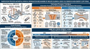
在全球能源轉型與淨零排放的宏觀趨勢下,大型燃氣複循環發電廠(Combined Cycle Power Plant, CCPP)的高能管線(High-Energy Piping, HEP)面臨前所未有的嚴苛服役條件。為配合再生能源發電的間歇性,CCPP 必須頻繁進行啟停與調峰操作,這使得管線材料長時間暴露於極端熱力學循環與物理瞬態中,進而引發嚴重的潛變-疲勞交互作用(Creep-Fatigue Interaction, CFI)。在傳統管線設計中,大量仰賴 1.5D 短半徑銲接彎頭;然而,由於其幾何應力集中區與熱影響區(Heat-Affected Zone, HAZ)高度重疊,該處已成為誘發第四型(Type IV)潛變破裂的致命弱點。 Amid the global macro-trend of energy transition and net-zero emissions, High-Energy Piping (HEP) in large Combined Cycle Power Plants (CCPP) faces unprecedentedly severe service conditions. To accommodate the intermittency of renewable energy generation, CCPPs must frequently perform start-stop and peak-shaving operations. This exposes piping materials to extreme thermodynamic cycles and physical transients for prolonged periods, triggering severe Creep-Fatigue Interaction (CFI). Traditional piping designs heavily rely on 1.5D short-radius welded elbows; however, because their geometric stress concentration zones highly overlap with the Heat-Affected Zones (HAZ), these areas have become fatal weak points prone to inducing Type IV creep rupture.
與此同時,美國機械工程師學會(ASME)針對壓力管線規範進行了半世紀以來最重大的變革。自 2024 年版起,ASME B31.1(動力管線規範)正式廢除原有的 Mandatory Appendix D,並預計於 2026 年全面強制導入 ASME B31J 規範。新規範以空間方向性彈性矩陣與有限元素分析(FEA)等級的應力強化係數(Stress Intensification Factor, SIF)取代了過去的單一經驗常數。在 B31J 的高解析度檢視下,傳統銲接彎頭往往面臨面外應力與扭轉應力嚴重超標的困境,促使工程實務界強烈轉向採用 3D 或 5D 大半徑冷作彎管(Cold Bending)。本研究以學術論文形式,深度剖析 CCPP 高能管線中銲接彎頭與 3D/5D 冷作彎管之施作流程與結構冶金衰退機制,並綜合多方利害關係人之觀點,探討 ASME B31J 規範演進對管線空間佈局、壁厚補償策略及全生命週期維護決策的深遠影響。 Concurrently, the American Society of Mechanical Engineers (ASME) has implemented the most significant paradigm shift in pressure piping codes in half a century. Starting with the 2024 edition, ASME B31.1 (Power Piping Code) officially abolished the legacy Mandatory Appendix D, and the ASME B31J standard is expected to be fully mandated by 2026. The new code replaces past singular empirical constants with spatial directional elasticity matrices and Finite Element Analysis (FEA)-grade Stress Intensification Factors (SIF). Under the high-resolution scrutiny of B31J, traditional welded elbows frequently face severe out-of-plane and torsional stress over-limit dilemmas, compelling the engineering practice to strongly pivot towards utilizing 3D or 5D large-radius cold bends. Structured as an academic paper, this study deeply analyzes the fabrication processes and structural metallurgical degradation mechanisms of welded elbows versus 3D/5D cold bends in CCPP HEP systems. By integrating the perspectives of multiple stakeholders, it explores the profound impacts of the ASME B31J code evolution on spatial layout, wall thickness compensation strategies, and full-lifecycle maintenance decision-making.
一、 緒論 / I. Introduction
1.1 CCPP 高能管線之營運環境與結構挑戰 / 1.1 Operating Environment and Structural Challenges of CCPP High-Energy Piping
現代 CCPP 系統具備極高的熱效率,其主蒸汽(Main Steam)與高溫再熱蒸汽(Hot Reheat)等高能管線的運行溫度通常超過 540°C,甚至可達 600°C 以上,並伴隨高達 3,000 psi 的內部蒸汽壓力1。過去的火力發電廠多以基載(Base-load)模式連續運轉,管線材料主要承受恆定的應力與溫度,其最主要的結構損傷機制為穩態潛變(Steady-state Creep),微裂紋多在設計壽命末期才迅速擴展3。 Modern CCPP systems possess extremely high thermal efficiency, with high-energy piping—such as Main Steam and Hot Reheat lines—typically operating at temperatures exceeding 540°C, or even reaching above 600°C, accompanied by internal steam pressures up to 3,000 psi1. Historically, thermal power plants operated continuously in base-load mode, where piping materials primarily endured constant stress and temperature. Their dominant structural damage mechanism was steady-state creep, with microcracks typically propagating rapidly only near the end of the design life3.
然而,現代 CCPP 系統面臨高度頻繁的啟停(Start-stop)與調峰(Peak-shaving)操作。當機組冷態或溫態啟動時,高溫蒸汽瞬間沖刷管壁內側,導致內壁急遽熱膨脹,而外壁仍處於相對低溫狀態;這種龐大的溫度梯度會在管壁內部產生極高的雙軸拉伸應力,進而引發低週疲勞(Low Cycle Fatigue, LCF)損傷3。當機組達到滿載並進入高溫持載(Dwell time)運轉階段時,疲勞交變應力在晶粒表面或幾何不連續處所產生的微裂紋與滑移帶(Slip bands),便成為空位(Vacancies)擴散的優勢通道,極大地加速了潛變孔洞(Creep cavitation)在晶界上的成核與成長3。 However, modern CCPP systems face highly frequent start-stop and peak-shaving operations. During cold or warm startups, high-temperature steam instantaneously flushes the inner pipe wall, causing rapid internal thermal expansion while the outer wall remains relatively cool. This massive temperature gradient generates extremely high biaxial tensile stresses within the pipe wall, subsequently inducing Low Cycle Fatigue (LCF) damage3. When the unit reaches full load and enters the high-temperature dwell time phase, microcracks and slip bands generated by alternating fatigue stresses at grain surfaces or geometric discontinuities become dominant channels for vacancy diffusion. This tremendously accelerates the nucleation and growth of creep cavitation along the grain boundaries3.
這兩種損傷機制並非單純的線性疊加,而是產生了極具破壞性的 CFI。在微觀層面上,密集的潛變孔洞反過來為疲勞裂紋的快速擴展提供了捷徑。這種「1+1>2」的交互加速效應,使得高溫合金管線在彎管彎背(Extrados)及銲接熱影響區的實際服役壽命,往往被大幅截斷至原始設計壽命的三分之一以下4。 These two damage mechanisms are not a mere linear superposition but forge a highly destructive CFI. On a microstructural level, dense creep cavities inversely provide shortcuts for the rapid propagation of fatigue cracks. This “1+1>2” interactive acceleration effect often drastically truncates the actual service life of high-temperature alloy piping at elbow extrados and weld HAZs to less than one-third of their original design life4.
1.2 壓力管線設計規範之歷史性變革 / 1.2 Historic Evolution of Pressure Piping Design Codes
過去半個世紀以來,全球的管線應力分析工程師在評估彎頭、三通等管件的系統柔性與疲勞壽命時,皆高度仰賴 ASME B31.1(動力管線)與 ASME B31.3(製程管線)規範中的 Mandatory Appendix D7。該附錄提供了一系列封閉形式(Closed-form)的經驗公式,用以計算 SIF 與柔性係數(k-factor)。然而,這些公式的基礎建立於 1950 年代 A.R.C. Markl 及其研究團隊針對 4 吋標準碳鋼管所進行的低週疲勞實驗數據9。 For the past half-century, global piping stress engineers evaluating the system flexibility and fatigue life of components like elbows and tees have heavily relied on Mandatory Appendix D in the ASME B31.1 (Power Piping) and ASME B31.3 (Process Piping) codes7. This appendix provided a series of closed-form empirical formulas to calculate SIFs and flexibility factors (k-factors). However, the foundation of these formulas was based on low-cycle fatigue test data conducted by A.R.C. Markl and his research team in the 1950s on 4-inch standard carbon steel pipes9.
隨著現代發電廠管線朝向大管徑、超厚壁以及 P91/P92 等高強度潛變增強型鐵素體鋼(Creep Strength Enhanced Ferritic Steels, CSEF)發展,材料的高溫潛變特性與幾何變形模式已與早期的薄壁碳鋼截然不同。舊有 Markl 疲勞理論的經驗公式逐漸顯露出理論盲區,導致工程設計經常陷入兩種極端:為迎合保守的單一 SIF 值而過度增加系統的柔性迴圈(Expansion loops),造成空間與材料的巨大浪費;或者無法真實捕捉複雜荷載下的局部峰值應力,使得高能管件潛藏未知的斷裂風險7。為解決此一根本性問題,ASME 推出並逐步強制實施 B31J 規範,從底層邏輯重構了管線系統的應力評估方法。 As modern power plant piping evolves towards larger diameters, ultra-thick walls, and the use of Creep Strength Enhanced Ferritic Steels (CSEF) such as P91/P92, the materials’ high-temperature creep characteristics and geometric deformation modes differ fundamentally from early thin-walled carbon steels. The empirical formulas of the legacy Markl fatigue theory gradually revealed theoretical blind spots. This caused engineering designs to frequently fall into two extremes: over-adding expansion loops to accommodate a conservatively high singular SIF value (resulting in a massive waste of space and materials), or failing to truly capture local peak stresses under complex loads (leaving high-energy fittings harboring unknown rupture risks)7. To resolve this fundamental issue, ASME introduced and is gradually mandating the B31J standard, reconstructing the stress evaluation methodology of piping systems from its foundational logic.
二、 2026 ASME B31J 規範演進與三維空間應力分析重構 / II. Evolution of the 2026 ASME B31J Code and Reconstruction of 3D Spatial Stress Analysis
2.1 傳統 Appendix D 經驗公式之學術侷限性 / 2.1 Academic Limitations of Traditional Appendix D Empirical Formulas
在傳統的 ASME B31 規範框架下,彎管的應力強化係數與柔性係數皆由一個無因次的幾何參數——「柔性特徵值」(Flexibility characteristic, h)來決定13。對於彎頭與冷作彎管,其定義方程式為: Under the traditional ASME B31 code framework, both SIFs and flexibility factors for pipe bends are determined by a dimensionless geometric parameter—the “Flexibility characteristic” (h)13. For elbows and cold bends, its defining equation is:
h=T⋅R1/r22
方程式中,T 代表彎管之公稱壁厚(Nominal wall thickness), R1為彎曲半徑(Bend radius),r2 則是連接直管之平均截面半徑(Mean radius of matching pipe)13。 In the equation, T represents the nominal wall thickness of the bend, R1 is the bend radius, and r2 is the mean radius of the matching pipe13.
在舊版規範中,系統不區分彎矩(Bending moment)的作用空間方向,一律將面內(In-plane)與面外(Out-of-plane)的應力集中效應合併計算,甚至直接取兩者中較大的一個 SIF 數值應用於整個節點;同時,對於扭轉力矩(Torsional moment)所引發的剪切應力,過去往往預設其 SIF 為 1.0,完全忽略了空間扭曲對管件疲勞壽命的影響4。這種純量(Scalar)處理方式無法真實反映三維管網中複雜應力場的疊加效應。 In older code editions, the system did not differentiate the spatial direction of the bending moment’s action. It uniformly merged in-plane and out-of-plane stress concentration effects, often directly applying the larger of the two SIF values to the entire node. Simultaneously, for shear stresses induced by torsional moments, the legacy code typically preset the SIF to 1.0, completely ignoring the impact of spatial twisting on the fitting’s fatigue life4. This scalar processing approach could not accurately reflect the superposition effects of complex stress fields within a 3D piping network.
2.2 ASME B31J 空間方向性彈性矩陣之數學解耦 / 2.2 Mathematical Decoupling of the ASME B31J Spatial Directional Elasticity Matrix
為追求更精確的工程預測,ASME B31J 規範將傳統的單一 SIF 徹底「空間解耦」為三維獨立矩陣4。根據 B31J 規範的 Table 1-1,彎管組件的應力強化係數被細分為以下三個獨立的空間向度: To pursue more accurate engineering predictions, the ASME B31J code thoroughly “spatially decouples” the traditional singular SIF into a three-dimensional independent matrix4. According to Table 1-1 of the B31J code, the SIFs for bend assemblies are subdivided into the following three independent spatial dimensions:
- 面內應力強化係數 / In-plane SIF (ii):當彎矩作用於彎管所在的幾何平面內,導致彎頭產生張角「打開(Opening)」或「閉合(Closing)」的變形趨勢時所引發的應力集中。傳統定義為 0.9/h2/3,而 B31J 則根據大量的物理實驗與有限元素分析(FEA)數據進行了更精確的邊界修正14。 Applied when the bending moment acts within the geometric plane of the bend, causing the elbow to tend to deform by “opening” or “closing”. The traditional definition was 0.9/h2/3, while B31J has made more precise boundary corrections based on extensive physical experiments and FEA data14.
- 面外應力強化係數 / Out-of-plane SIF (io):當彎矩的作用向量垂直於彎管平面,迫使管件發生橫向「扭曲(Twisting)」時所應用的係數。傳統定義為 0.75/h2/3 15。 The factor applied when the bending moment’s action vector is perpendicular to the bend plane, forcing the component to undergo lateral “twisting”. The traditional definition was 0.75/h2/3 15.
- 扭轉應力強化係數 / Torsional SIF (it):B31J 規範首次在管線動態與位移應力分析中,針對多種管件強制導入it ≠ 0 的條件。此舉對於精確計算管網熱膨脹轉移至末端旋轉機械(如高壓汽輪機、大型離心式壓縮機)的噴嘴荷重(Nozzle loads)至關重要8。 For the first time in piping dynamic and displacement stress analyses, the B31J code mandates conditions where it ≠ 1.0 for various fittings. This move is crucial for accurately calculating nozzle loads transferred from pipe network thermal expansion to terminal rotating machinery (e.g., high-pressure steam turbines, large centrifugal compressors)8.
此外,B31J 同時將柔性係數(Flexibility Factor, k)進行了方向性細分(ki,ko,kt),真實反映管件在不同扭轉與彎曲力矩下的幾何剛度變化9。在 B31.1-2024 年版中,Appendix D 已被正式刪除,所有針對位移應力範圍(Displacement stress range, SE)的計算皆強制導入 B31J 的解耦矩陣公式: Furthermore, B31J concurrently subdivides the flexibility factor (k-factor) directionally (ki,ko,kt), truly reflecting the geometric stiffness changes of the fitting under different torsional and bending moments9. In the B31.1-2024 edition, Appendix D has been officially deleted, and all calculations for the displacement stress range (SE) strictly mandate the incorporation of B31J’s decoupled matrix formula:
SE=√[(iiMi )2+(ioMo)2+(itMt)2]/Z
在評估自重與內壓等一次應力(Primary stress)引起的持續應力(Sustained stress)時,B31J 亦引入了持續應力指數(Sustained Stress Index, SSI),其值設定為 max(0.75i,1.0),用以防止管件發生不可逆的塑性崩塌8。 When evaluating sustained stress caused by primary stresses like self-weight and internal pressure, B31J also introduces the Sustained Stress Index (SSI), set to max(0.75i,1.0), to prevent irreversible plastic collapse of the fitting8.
2.3 B31J Appendix A 實驗程序與 FEA 驗證標準 / 2.3 B31J Appendix A Experimental Procedures and FEA Validation Standards
針對特殊幾何形狀、超厚壁或非標準(Non-standard)的管件(如具有特殊過渡倒角的修邊彎頭 Trimmed elbows),ASME B31J 的 Nonmandatory Appendix A 提供了一套嚴謹的標準化實驗與分析程序10。該程序允許工程師透過兩種路徑獲取符合法規的 SIF 與 k-factor: For components with special geometries, ultra-thick walls, or non-standard fittings (such as trimmed elbows with special transition chamfers), ASME B31J’s Nonmandatory Appendix A provides a rigorous set of standardized experimental and analytical procedures10. This procedure allows engineers to obtain code-compliant SIFs and k-factors via two pathways:
第一種為物理應變規測試(Strain-gauge testing)。透過將真實比例的金屬管件放置於疲勞測試機台上,施加反覆的循環位移,並透過精密應變規記錄其達到漏水或巨觀斷裂時的疲勞循環次數(通常目標區間介於 5,000 至 200,000 次之間)19。將測得的峰值應力與理論直管的名目應力(Nominal stress, M/Z)進行比對,從而求得精確的 SIF 10。 The first is physical strain-gauge testing. By placing a real-scale metallic fitting on a fatigue testing rig and applying repeated cyclic displacements, precision strain gauges record the number of fatigue cycles until leakage or macroscopic rupture occurs (the target range usually falls between 5,000 and 200,000 cycles)19. The measured peak stress is then compared to the theoretical nominal stress (M/Z) of a straight pipe to calculate the precise SIF 10.
第二種為有限元素分析(Finite Element Analysis, FEA)。隨著計算力學的進步,B31J 承認透過建立精細的三維實體網格(Solid mesh)或殼狀網格(Shell mesh),並遵循 WRC 429 準則排除因網格奇異性(Singularities)造成的無限應力集中後,所推導出的峰值應力比值可直接作為合規的 SIF 數據7。這為工程界在新材料與新工法(如大半徑冷作彎管)的應用上提供了堅實的法規依據。 The second pathway is Finite Element Analysis (FEA). With advancements in computational mechanics, B31J recognizes that the ratio of peak stresses—derived by building refined 3D solid meshes or shell meshes and adhering to WRC 429 guidelines to eliminate infinite stress concentrations caused by mesh singularities—can directly serve as compliant SIF data7. This provides a solid regulatory basis for the engineering sector’s application of new materials and advanced manufacturing techniques (like large-radius cold bends).
2.4 CAESAR II 模型構建與「應力分析衝擊」效應 / 2.4 CAESAR II Modeling and the “Stress Analysis Shock” Effect
當 ASME B31J 演算法被深度整合至 CAESAR II、AutoPIPE 等主流管線應力分析軟體後,工程界的佈局設計思維發生了根本性的轉變10。在軟體的實務建模中,工程師不再能將彎頭或三通視為單一的剛性節點(Rigid node),而必須精確輸入其真實的壁厚、平均半徑、支管尺寸等參數,以觸發軟體後台自動調用 B31J 的非線性矩陣22。 When the ASME B31J algorithms were deeply integrated into mainstream piping stress analysis software such as CAESAR II and AutoPIPE, the engineering community’s layout design mindset underwent a fundamental shift10. In practical software modeling, engineers can no longer treat elbows or tees as singular rigid nodes; instead, they must accurately input parameters such as true wall thickness, mean radius, and branch dimensions to trigger the software’s backend to automatically invoke B31J’s nonlinear matrices22.
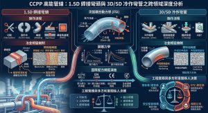
這種技術進步同時在產業界引發了所謂的「應力分析衝擊(Stress Analysis Shock)」。許多在舊版 Appendix D 規範下被判定為「勉強合格」的傳統 1.5D 銲接彎頭,在接受 B31J 空間解耦方程式的高解析度檢視後,其面外應力(Out-of-plane stress)與扭轉應力(Torsional stress)往往瞬間突破規範的容許應力上限(Allowable stress limit)11。為使系統重新符合 2026 年版規範的安全性要求,捨棄傳統短半徑銲接彎頭,轉而採用具備極低 SIF 值的 3D/5D 大半徑冷作彎管,遂成為高能動力管線設計的最佳解答。 This technological advancement simultaneously triggered what the industry terms a “Stress Analysis Shock.” Many traditional 1.5D welded elbows that were deemed “marginally compliant” under the legacy Appendix D code, upon facing the high-resolution scrutiny of B31J’s spatial decoupling equations, frequently found their out-of-plane and torsional stresses instantaneously breaching the allowable stress limits11. To make the system compliant again with the safety requirements of the 2026 code edition, abandoning traditional short-radius welded elbows in favor of 3D/5D large-radius cold bends—which possess extremely low SIF values—has become the optimal solution for high-energy power piping design.
三、 傳統 1.5D 銲接彎頭之施作流程、冶金衰退與破裂機制 / III. Fabrication Process, Metallurgical Degradation, and Failure Mechanisms of Traditional 1.5D Welded Elbows
在探討為何新規範與現代工程趨勢強烈傾向採用冷作彎管之前,必須深入剖析傳統 1.5D 短半徑銲接彎頭(Welded Elbows)在施作流程中隱藏的冶金缺陷,以及其在極端服役環境下的力學衰退機制。 Before exploring why the new code and modern engineering trends strongly favor cold bends, it is imperative to deeply analyze the metallurgical defects hidden within the fabrication process of traditional 1.5D short-radius welded elbows, as well as their mechanical degradation mechanisms in extreme service environments.
3.1 P91/P92 高階合金之微觀組織與化學成分敏感性 / 3.1 Microstructural and Chemical Composition Sensitivity of P91/P92 High-Grade Alloys
CCPP 主蒸汽管線廣泛採用的 P91 鋼(ASTM A335 P91, 9Cr-1Mo-V)屬於 ASME P-No. 15E 材料組別。其卓越的高溫抗潛變能力並非單純依賴合金元素的固溶強化,而是建構在極其精密的微觀組織之上:以回火馬氏體(Tempered Martensite)為基體,並在原奧氏體晶界(Prior Austenite Grain Boundaries, PAGBs)與板條邊界(Lath boundaries)均勻分佈著奈米級的析出強化相13。 The P91 steel (ASTM A335 P91, 9Cr-1Mo-V) widely utilized in CCPP main steam piping belongs to the ASME P-No. 15E material group. Its outstanding high-temperature creep resistance does not rely solely on the solid-solution strengthening of alloying elements; rather, it is built upon an extremely precise microstructure: a Tempered Martensite matrix uniformly interspersed with nano-scale precipitation-strengthening phases along Prior Austenite Grain Boundaries (PAGBs) and lath boundaries13.
這些析出物主要分為兩類:富鉻的 M23C6碳化物(提供晶界穩定作用),以及極細小且彌散分佈的 MX 碳氮化物(如 NbC, VN)10。這些奈米級微粒透過「齊納釘紮效應(Zener Pinning Effect)」,在 600°C 的高溫下依然能強勢阻礙位錯的滑移與亞晶界的遷移,從而賦予材料極高的潛變抗力。 These precipitates are mainly divided into two categories: chromium-rich M23C6 carbides (providing grain boundary stabilization) and extremely fine, homogeneously dispersed MX carbonitrides (such as NbC, VN)10. Through the “Zener Pinning Effect,” these nano-scale particles can still powerfully impede dislocation slip and subgrain boundary migration even at high temperatures of 600°C, thereby endowing the material with exceptionally high creep resistance.
然而,要維持這種精密的組織,P91 的化學成分容許度極低。例如,碳(Carbon)含量必須維持在 ≧0.09% 以確保足夠的碳化物析出;鈮(Niobium)需 ≧0.03% 以形成穩定的 NbC。更關鍵的是,銲材中的錳(Mn)與鎳(Ni)總和強烈影響著鋼材的相變溫度。當 (Mn+Ni) 總和超過 1.0% 時,材料的下臨界點溫度(AC1)會顯著降低,這直接壓縮了後續熱處理的安全操作視窗13。 However, maintaining this precise microstructure leaves very little tolerance for chemical composition variance in P91. For instance, Carbon content must be maintained at ≧0.09% to ensure sufficient carbide precipitation; Niobium requires ≧0.03% to form stable NbC. Crucially, the sum of Manganese (Mn) and Nickel (Ni) in the filler metal strongly influences the steel’s phase transformation temperatures. When the sum of (Mn+Ni) exceeds 1.0%, the material’s lower critical temperature (AC1) decreases significantly, directly compressing the safe operational window for subsequent heat treatments13.
3.2 銲接熱循環下之結構衰退與 Type IV 潛變破裂 / 3.2 Structural Degradation and Type IV Creep Rupture Under Welding Thermal Cycles
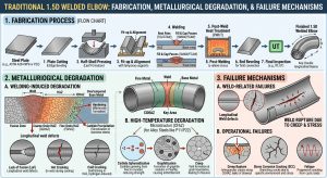
當 1.5D 彎頭與直管於現場進行對接銲接(如 GTAW 配合 SMAW)時,銲接電弧的極高熱量會在母材兩側產生寬廣的熱影響區(HAZ)。針對 P9x 材料,HAZ 依據受熱溫度的不同,可細分為粗晶區(CGHAZ)、細晶區(FGHAZ)以及最致命的臨界熱影響區(Intercritical HAZ, ICHAZ)11。 When 1.5D elbows and straight pipes are butt-welded on-site (e.g., GTAW combined with SMAW), the intense heat of the welding arc generates a broad Heat-Affected Zone (HAZ) on both sides of the base metal. For P9x materials, the HAZ can be subdivided based on varying thermal exposure into the Coarse-Grained HAZ (CGHAZ), Fine-Grained HAZ (FGHAZ), and the most lethal Intercritical HAZ (ICHAZ)11.
在 ICHAZ 中,材料經歷了介於 AC1 與上臨界溫度 AC3 之間的熱循環,導致微觀組織發生不完全奧氏體化(Incomplete Austenitization)。熱力學的劇烈波動使得原本能提供強大潛變抗力的 MX 相發生部分溶解,而 M23C6 碳化物則發生粗化現象11。這種微觀冶金學上的「軟化」是完全不可逆的。 In the ICHAZ, the material undergoes a thermal cycle between the lower critical temperature AC1 and upper critical temperature AC3, leading to Incomplete Austenitization of the microstructure. Severe thermodynamic fluctuations cause the MX phases—which originally provided formidable creep resistance—to partially dissolve, while the M23C6 carbides experience coarsening11. This microscopic metallurgical “softening” is completely irreversible.
在 CCPP 頻繁啟停所引發的 CFI 環境下,上述的 ICHAZ 軟化帶首當其衝。美國電力研究院(EPRI)的研究指出,隱藏於此帶的微觀潛變空洞會緩慢且無聲地成核與聚集11。其最可怕的特徵在於「晚期突發性」:裂紋的發展極度隱蔽,難以透過常規的射線檢測(RT)或超音波檢測(UT)在早期發現;一旦微孔洞的聚合跨過臨界尺寸,便會瞬間擴展為貫穿管壁的巨觀裂紋,引發極具毀滅性的 Type IV 潛變斷裂,造成未漏先破(Break-before-leak)的工安災難8。 Under the CFI environments induced by frequent CCPP startups and shutdowns, the aforementioned ICHAZ softening band bears the brunt of the damage. Research by the Electric Power Research Institute (EPRI) points out that microscopic creep voids hidden within this zone will nucleate and coalesce slowly and silently11. Its most terrifying characteristic is “late-stage suddenness”: crack development is highly concealed and difficult to detect early via conventional Radiographic Testing (RT) or Ultrasonic Testing (UT); once the coalescence of micro-voids crosses a critical size threshold, it instantaneously propagates into a macroscopic crack penetrating the pipe wall, triggering devastating Type IV creep rupture and causing a “break-before-leak” industrial disaster8.
此外,在異種金屬銲接(Dissimilar Metal Welds, DMW,如 P91 與沃斯田鐵不銹鋼銲接)中,除了熱膨脹係數不匹配引發的熱疲勞外,更會發生「碳遷移(Carbon Migration)」效應。在高溫服役或熱處理期間,碳原子受化學勢梯度驅動,從 P9x 側越過熔合線向高鉻側擴散,導致 P9x 側形成硬度極低的「碳貧化帶(Carbon Depleted Zone)」,進一步成為接頭的最弱連結25。 Furthermore, in Dissimilar Metal Welds (DMW, such as welding P91 to austenitic stainless steel), in addition to thermal fatigue caused by mismatched coefficients of thermal expansion, a “Carbon Migration” effect occurs. During high-temperature service or heat treatment, carbon atoms driven by chemical potential gradients diffuse from the P9x side across the fusion line toward the high-chromium side, resulting in a severely low-hardness “Carbon Depleted Zone” on the P9x side, which further acts as the weakest link of the joint25.
| 銲接彎頭潛在破裂機制 / Potential Failure Mechanisms of Welded Elbows | 發生位置 / Location | 物理/冶金學成因 / Physical/Metallurgical Causes | 對結構完整性之危害特徵 / Hazard Characteristics to Structural Integrity |
| Type IV 潛變破裂 / Type IV Creep Rupture | ICHAZ (臨界熱影響區 / Intercritical HAZ) | 不完全奧氏體化導致 MX 相溶解與碳化物粗化,喪失 Zener 釘紮效應 / Incomplete austenitization causing MX phase dissolution and carbide coarsening, losing Zener pinning effect. | 極高,具晚期突發性,易導致未漏先破災難 / Extremely high; exhibits late-stage suddenness, easily causing break-before-leak disasters.8 |
| 晶界液化開裂 / Liquation Cracking | PMZ (部分熔化區 / Partially Melted Zone) | 局部高溫使晶界低熔點雜質液化,隨銲縫收縮產生微觀撕裂 / Local high temps liquefy low-melting-point impurities at grain boundaries, causing micro-tears during weld shrinkage. | 高,潛伏期長,為低週疲勞提供初始裂紋擴展源 / High; long latency, providing initial crack propagation sources for low-cycle fatigue.8 |
| 碳遷移與熱疲勞撕裂 / Carbon Migration & Thermal Fatigue Tearing | 熔合線 / Fusion Line (DMW 接頭處 / DMW Joints) | 兩端材料化學勢不同驅動碳擴散,形成軟化碳貧化帶與脆化富碳帶 / Distinct chemical potentials drive carbon diffusion, forming softened carbon-depleted and embrittled carbon-rich zones. | 中至高,在 CCPP 頻繁熱機循環下加速疲勞撕裂 / Medium to high; accelerates fatigue tearing under frequent CCPP thermo-mechanical cycling.19 |
| 應力鬆弛開裂 / Stress Relaxation Cracking (SRC) | 銲道內部及粗晶區 / Weld Interior & CGHAZ | 殘餘拉伸應力於局部薄弱晶界強制釋放,且因應變老化導致韌性下降 / Residual tensile stress forcefully released at weak grain boundaries; toughness drops due to strain aging. | 中,多發生於厚壁管件未經充分 PWHT 之情況 / Medium; mostly occurs in thick-walled fittings lacking sufficient PWHT.8 |
3.3 嚴苛的銲後熱處理 (PWHT) 流程與失效風險 / 3.3 Stringent Post-Weld Heat Treatment (PWHT) Procedures and Failure Risks
為釋放銲接殘餘應力並使堅硬脆化的馬氏體回火,ASME Section I、Section VIII 及 B31.1 皆嚴格規定了 P91/P92 的銲後熱處理(PWHT)程序24。這是一項容錯率極低的精密熱處理工法,完整的標準流程包含四個關鍵階段: To relieve residual welding stresses and temper the hard, embrittled martensite, ASME Section I, Section VIII, and B31.1 strictly stipulate the Post-Weld Heat Treatment (PWHT) procedures for P91/P9224. This is a precision heat-treatment process with an extremely low error tolerance. The complete standard procedure includes four key stages:
- 預熱(Preheat):銲接全程必須維持 200°C 至 204°C 以上的預熱溫度,以減緩冷卻速率並防止擴散氫滯留引發冷裂紋(Cold cracking)24。 Preheat: A preheat temperature above 200°C to 204°C must be maintained throughout the entire welding process to slow the cooling rate and prevent diffusible hydrogen retention from causing cold cracking24.
- 氫烘烤(Hydrogen Bake-out / Post-heating):銲接完成後嚴禁直接冷卻,必須立即透過電阻加熱將接頭提升至 300°C 至 350°C,並保溫 2 至 3 小時。此步驟強制將殘存於厚壁銲道內的擴散氫驅趕逸出。 Hydrogen Bake-out (Post-heating): Direct cooling after welding is strictly prohibited. The joint must immediately be raised via electrical resistance heating to 300°C–350°C and held for 2 to 3 hours. This step forcibly drives out diffusible hydrogen trapped within the thick-walled weld.
- 冷卻至馬氏體轉變完成溫度 (Mf) / Cooling to Martensite Finish Temp (Mf):氫烘烤後,必須讓銲口完全冷卻至 96°C 以下(通常建議低於 90°C)。若未冷卻至 Mf 點即進行 PWHT,殘留的奧氏體將在熱處理後轉變為脆性的未回火馬氏體,埋下致命隱患24。 Cooling to Mf: After the hydrogen bake-out, the weld must be allowed to cool completely below 96°C (usually recommended below 90°C). If PWHT is initiated without cooling below the Mf point, retained austenite will transform into brittle untempered martensite after heat treatment, embedding a fatal hazard24.
- PWHT 升溫與保溫(Soaking) / PWHT Ramp-up and Soaking:以極度平緩的升溫速率(厚壁管通常 ≦55°C/hr)將接頭加熱至 730°C 至 760°C 的目標溫度,保溫時間依據壁厚計算,標準為每英吋厚度 1 小時(且最低不得少於 2 小時)27。 Soaking: The joint is heated at an extremely gradual ramp rate (typically ≦55°C/hr for thick-wall pipes) to a target temperature of 730°C to 760°C. The soak time is calculated based on wall thickness, standardized at 1 hour per inch of thickness (and no less than 2 hours minimum)27.
在此過程中,最大的工程風險在於「溫度視窗(Temperature Window)的越界」。如前所述,若銲材的 (Mn+Ni) 含量偏高,材料的 AC1 溫度可能降至 780°C 甚至更低。若現場熱處理儀器失準或受外部環境干擾,使得 PWHT 溫度短暫超過 AC1,材料便會發生災難性的重新奧氏體化(Re-austenitizing)13。此外,如果在升溫或保溫階段發生電力中斷(Power failure),則必須依據降溫幅度判定是否需要從頭執行整套 PWHT 循環,這對專案時程與現場品管構成了嚴峻挑戰。 During this process, the greatest engineering risk lies in exceeding the “Temperature Window.” As previously mentioned, if the filler metal’s (Mn+Ni) content is high, the material’s AC1 temperature might drop to 780°C or even lower. If on-site heat treatment instruments are inaccurate or affected by external environmental disturbances, causing the PWHT temperature to briefly exceed AC1, the material will experience catastrophic re-austenitizing13. Additionally, if a power failure occurs during the ramp-up or soaking phases, it must be determined based on the temperature drop magnitude whether the entire PWHT cycle needs to be re-executed from scratch, posing severe challenges to project schedules and field QA/QC.
3.4 ASME B31.1 銲接強度折減係數 (WSRF) 之厚壁化懲罰 / 3.4 Thickness Penalty of ASME B31.1 Weld Strength Reduction Factor (WSRF)
針對前述 HAZ 區無可避免的微觀組織退化,ASME B31.1 在 Table 102.4.7-1 中引入了懲罰性的「銲接強度折減係數(Weld Strength Reduction Factor, WSRF,代號 W)」1。根據規範 Eq (7),直管或銲接彎管在承受內部蒸汽設計壓力(P)時,其最小設計壁厚 tm 的計算公式為1: Addressing the unavoidable microstructural degradation of the HAZ mentioned above, ASME B31.1 introduces a punitive “Weld Strength Reduction Factor” (WSRF, denoted as W) in Table 102.4.7-11. According to Code Eq (7), when straight pipes or welded bends sustain internal steam design pressure (P), their minimum design wall thickness tm is calculated as1:
tm=[P⋅Do/2(S⋅E⋅W+P⋅y)]+A
公式中,S 為材料於設計溫度下的容許應力(Allowable stress),E 為銲接接頭效率,y 為溫度相依係數,A 為腐蝕或加工容裕,而 W 即為 WSRF 33。 In the equation, S is the material’s allowable stress at the design temperature, E is the weld joint efficiency, y is a temperature-dependent coefficient, A is the allowance for corrosion or threading, and W is the WSRF 33.
對於 P91 鋼而言,在室溫或中低溫環境下,W 值為 1.0;但當設計溫度進入潛變範圍(Creep range,例如 540°C 至 600°C 以上)時,W 值會隨溫度攀升而斷崖式下跌,甚至降至 0.7 乃至 0.532。這意味著在相同的設計壓力下,工程師必須將存在銲道的管件壁厚大幅增加,以彌補 HAZ 強度的損失。 For P91 steel, in ambient or moderately low-temperature environments, the W value is 1.0. However, when the design temperature enters the creep range (e.g., above 540°C to 600°C), the W value plummets precipitously as temperature climbs, dropping to 0.7 or even 0.532. This dictates that under the same design pressure, engineers must significantly increase the wall thickness of fittings containing weld seams to compensate for the HAZ strength loss.
然而,這種「厚壁化」策略產生了嚴重的反效果:壁厚增加直接導致管件的柔性特徵值 h 下降,進一步推高了 B31J 矩陣中的 SIF 值,並使得系統整體剛性(Stiffness)暴增12。剛性的提升使得管線無法自行吸收因溫度驟變產生的巨大熱膨脹位移,最終將無處宣洩的破壞性推力轉嫁給端點的汽輪機或釋放於沿線管架,形成難以解套的應力惡性循環12。這種因銲道而起的系統性硬傷,正是推動現代工程界轉向冷作彎管的核心驅動力。 However, this “thick-walling” strategy creates severe adverse effects: the increased wall thickness directly causes a drop in the fitting’s flexibility characteristic h, further inflating the SIF values in the B31J matrix and causing the system’s overall stiffness to skyrocket12. This heightened stiffness prevents the piping from self-absorbing the massive thermal expansion displacements caused by sudden temperature changes, ultimately transferring the destructive, unvented thrust loads onto terminal steam turbines or releasing them along pipe racks, forging an inescapable vicious cycle of stress12. This systemic flaw originating from weld seams is the core driver pushing modern engineering toward cold bends.
四、 3D/5D 大半徑冷作彎管之施作流程、流固耦合與熱處理修復 / IV. Fabrication Process, Fluid-Solid Coupling, and Heat Treatment Restoration of 3D/5D Large-Radius Cold Bends
為打破 1.5D 銲接彎頭伴隨的 HAZ 衰退與 WSRF 懲罰困局,2026 年版的 ASME B31.1 與 B31J 強烈引導工程界採用「以彎代銲(Bend instead of Weld)」的策略。利用高精度數控(CNC)彎管機,在室溫或次臨界溫度下將高規格無縫鋼管直接加工為 3D 或 5D 比例的冷作彎管(Cold Bending),已成為現代 CCPP 動力管線佈局的標配11。 To break the deadlock of HAZ degradation and WSRF penalties associated with 1.5D welded elbows, the 2026 editions of ASME B31.1 and B31J strongly guide the engineering sector to adopt a “Bend instead of Weld” strategy. Utilizing high-precision CNC bending machines to directly process high-grade seamless steel pipes into 3D or 5D proportioned Cold Bends at room or subcritical temperatures has become the standard configuration for modern CCPP power piping layouts11.
4.1 冷彎塑性應變機制與 ASME B31.1 壁厚減薄法則 / 4.1 Cold Bending Plastic Strain Mechanisms and ASME B31.1 Wall Thinning Rules
冷作彎曲工法係透過強大的機械力矩,迫使直管產生永久性的塑性變形。在成形過程中,力學幾何會產生顯著的不對稱性:彎管的外弧側(Extrados)承受極大的拉伸應變,必然導致管壁實體發生「壁厚減薄(Wall Thinning)」現象;相對地,內弧側(Intrados)則承受壓縮應變而向內增厚,同時整體管截面的中性軸(Neutral axis)會發生偏移,產生一定程度的橢圓化(Ovality)畸變11。 The cold bending process forces straight pipes to undergo permanent plastic deformation via immense mechanical torque. During forming, significant mechanical asymmetry occurs: the extrados (outer arc) of the bend sustains massive tensile strain, inevitably leading to physical “Wall Thinning”; conversely, the intrados (inner arc) bears compressive strain and thickens inwards, while the overall cross-sectional neutral axis shifts, creating a certain degree of Ovality distortion11.
為確保經過劇烈拉伸減薄後的外弧側,其最薄處的實體厚度依然大於或等於依據內壓公式所計算出的最小設計壁厚 tm,ASME B31.1 規範第 102.4.5 節(Table 102.4.5)明確且強制規定了各彎曲半徑所必須預留的「母管補償餘裕(Bend Thinning Allowance)」35。詳細規定如下表所示: To ensure that the thinnest point of the extrados, after severe tensile thinning, remains greater than or equal to the minimum design wall thickness tm calculated via internal pressure equations, Section 102.4.5 (Table 102.4.5) of ASME B31.1 explicitly and mandatorily stipulates the “Bend Thinning Allowance” that must be reserved for various bend radii35. The detailed requirements are as follows:
| 彎管幾何半徑比 (R/D) / Bend Radius Ratio (R/D) | B31.1 法定壁厚減薄補償餘裕 / B31.1 Statutory Wall Thinning Allowance | 彎曲工法特徵與材料採購影響評估 / Bend Process Features & Material Procurement Impact |
| ≧ 6D 彎管 / Bends ≧ 6D | 1.06 tm (需預留 6% 餘裕 / Requires 6% allowance) | 拉伸變形極小,可直接採用廠內常規直管進行加工 / Minimal tensile deformation; standard straight pipes can be directly processed. |
| 5D 彎管 / 5D Bends | 1.08 tm (需預留 8% 餘裕 / Requires 8% allowance) | 工程經濟學最佳平衡點。8% 餘裕絕大多數可由市售標準 Schedule 鋼管的固有裕度吸收,無需耗費巨資特製母管 / Optimal Engineering Economics Balance Point. The 8% allowance can mostly be absorbed by the inherent margins of commercial standard Schedule pipes, avoiding costly custom parent pipes.35 |
| 4D 彎管 / 4D Bends | 1.14 tm (需預留 14% 餘裕 / Requires 14% allowance) | 拉伸變形顯著,部分高壓等級可能需向鋼廠客製化提升局部壁厚 / Significant tensile deformation; some high-pressure classes may require custom localized thickness boosts from mills. |
| 3D 彎管 / 3D Bends | 1.25 tm (需預留 25% 餘裕 / Requires 25% allowance) | 材料成本劇增區。局部減薄率極高,必須採購特製的超厚母管 (Extra-heavy parent pipe) 以應對厚度損失,大幅推高整廠建置成本並增加支撐荷重 / Material Cost Spike Zone. Extremely high local thinning requires procuring extra-heavy parent pipes, drastically inflating plant build costs and increasing support loads. |
從上表可清晰看出,雖然 3D 與 5D 均屬於冷作彎管,但在工程實務與材料經濟學上存在著天壤之別。5D 彎管由於彎曲半徑較大,外弧區的應力得到舒緩,僅需 8% 的壁厚補償。這使得 EPC 統包商能在完全不需採購特製超厚母管的前提下,完美符合 B31.1 的承壓邊界完整性要求,達成管線整體減重與原料成本最佳化的雙贏8。 As clearly seen from the table above, although both 3D and 5D fall under cold bends, they represent a world of difference in engineering practice and material economics. Due to its larger bend radius, the stress in the extrados of a 5D bend is alleviated, requiring only an 8% wall thickness compensation. This enables EPC contractors to perfectly meet B31.1 pressure boundary integrity requirements without procuring custom extra-heavy parent pipes, achieving a win-win for overall piping weight reduction and raw material cost optimization8.
4.2 應變率之理論計算與 5% 至 20% 法定放寬區間 / 4.2 Theoretical Calculation of Strain Rate and the 5% to 20% Statutory Relaxation Range
在早期,業界普遍對 P91 這類高度依賴精確回火馬氏體基體的 CSEF 鋼材進行大角度冷彎抱持疑慮,擔憂劇烈的塑性變形會引發嚴重的晶格畸變與差排堆積,進而扼殺其高溫延展性。然而,新規範以科學的應變率量化方式打破了此一迷思5。 In early years, the industry generally held reservations about deep-angle cold bending of CSEF steels like P91, which rely highly on precise tempered martensite matrices. There were concerns that severe plastic deformation would induce massive lattice distortions and dislocation pile-ups, thereby choking its high-temperature ductility. However, the new codes shattered this myth through scientific quantification of strain rates5.
冷彎過程對管材內部組織的拉伸破壞程度可透過理論塑性應變率(Strain Rate, ϵ)進行幾何量化。其計算公式為11: The degree of tensile damage inflicted on the material’s internal microstructure during cold bending can be geometrically quantified via the theoretical plastic Strain Rate (ϵ). Its calculation formula is11:
ϵ=ro/R1 ×100%=Do/(2R1 )×100%
將 CCPP 主流規格代入公式驗算:若採用 3D 彎管(R1 =3Do),外弧區承受的最大拉伸應變率約為 16.7%;若採用 5D 彎管(R1 =5Do),其成形應變率則降至約 10.0%8。 By plugging in mainstream CCPP specifications: if a 3D bend (R1 =3Do) is used, the maximum tensile strain rate sustained at the extrados is roughly 16.7%; for a 5D bend (R1 =5Do), the forming strain rate drops to about 10.0%8.
這兩項數值的意義極為重大。ASME B31.1 第 129.3 節(Table 129.3.1-1)與 B31J 皆明確指出,只要冷作成形後的應變率精準落入「5% 至 20%」的過渡區間內,工程師即可透過後續的「彎後熱處理(Post-Bend Heat Treatment, PBHT)」來完全修復材料的微觀組織,重新獲取符合規範要求的高溫潛變抗力13。這套科學放寬機制,正式確立了 3D/5D 冷彎工法在頂級動力管線上的合法性與正當性。 The significance of these two figures is monumental. ASME B31.1 Section 129.3 (Table 129.3.1-1) and B31J both explicitly state that as long as the post-cold-forming strain rate falls precisely within the “5% to 20%” transitional relaxation range, engineers can completely restore the material’s microstructure via subsequent “Post-Bend Heat Treatment (PBHT)”, regaining high-temperature creep resistance that meets code requirements13. This scientific relaxation mechanism officially establishes the legality and validity of the 3D/5D cold bending process for top-tier power piping.
4.3 組織重塑工程:感應加熱彎後熱處理 (IH-PBHT) 與熱彎技術之比較 / 4.3 Microstructural Restoration Engineering: IH-PBHT vs. Hot Bending Technology
針對 P91 高能冷作彎管的 PBHT,冶金學上分為「次臨界熱處理(Subcritical PBHT)」與「正火加回火(Normalizing & Tempering, N&T)」兩種路徑5。 For the PBHT of P91 high-energy cold bends, metallurgy presents two pathways: “Subcritical PBHT” and “Normalizing & Tempering (N&T)”5.
次臨界熱處理雖然在操作上較為簡易(溫度控制在 AC1 以下),但只能部分釋放冷作造成的龐大殘餘應力;未被消除的高密度位錯將在隨後的高溫服役期間,成為 Laves 相異常粗化的成核點,導致固溶強化機制提早瓦解,潛變壽命可能縮減近兩個數量級。 Although Subcritical PBHT is operationally simpler (temperature kept below AC1), it can only partially release the massive residual stresses caused by cold working. Unrelieved high-density dislocations will act as nucleation sites for abnormal Laves phase coarsening during subsequent high-temp service, leading to early collapse of solid-solution strengthening and potentially slashing creep life by nearly two orders of magnitude.
因此,最為徹底且被先進工程界推崇的修復工法為「正火加回火」。 Therefore, the most thorough and highly esteemed restoration process in advanced engineering circles is “Normalizing & Tempering”.
- 正火(Normalization):將彎管均勻加熱至 AC3 以上(約 1040°C 至 1080°C),使其完全奧氏體化,藉由高溫原子擴散徹底抹除所有的晶格畸變與加工硬化,並強制碳氮化物重新完全固溶於基體中,隨後空冷形成新鮮未回火馬氏體。 Normalization: The bend is uniformly heated above AC3 (approx. 1040°C to 1080°C) to fully austenitize it. Through high-temp atomic diffusion, all lattice distortions and work hardening are thoroughly erased, forcing carbonitrides to completely re-dissolve into the matrix, followed by air cooling to form fresh untempered martensite.
- 回火(Tempering):接著於 730°C 至 780°C 進行高溫回火,完美釋放相變內應力,促使 MX 相與 M23C6 碳化物再次均勻且彌散地析出,使其潛變延展性恢復如初。 Tempering: This is followed by high-temp tempering between 730°C and 780°C to perfectly release phase transformation internal stresses, promoting the uniform and dispersed re-precipitation of MX phases and M23C6 carbides, restoring its original creep ductility.
由於 5D 彎管的本體無任何銲道,工程師得以擺脫傳統保溫爐的空間限制,直接在工廠或現場運用「感應加熱彎後熱處理(Induction Heating PBHT, IH-PBHT)」技術。IH-PBHT 透過高頻電磁場精準控制管壁內外的溫度均勻度與升降溫速率,能完美執行上述嚴苛的 N&T 循環,確保材料不發生局部熱劣化11。 Because the body of a 5D bend contains no welds, engineers are freed from the spatial constraints of traditional holding furnaces and can utilize “Induction Heating PBHT (IH-PBHT)” technology directly in the shop or field. Through high-frequency electromagnetic fields, IH-PBHT precisely controls the internal and external wall temperature uniformity and ramp rates, flawlessly executing the stringent N&T cycle and ensuring no localized thermal degradation occurs11.
值得一提的是,雖然「熱感應彎管(Induction Bending / Hot Bending)」在處理大管徑時具備不產生回彈(Springback)的優勢,但因其在成型過程中管材需被持續加熱至 850°C 至 1100°C 之間,會永久性地改變鋼材的碳當量(CE)或降低抗點蝕當量(PREN),甚至引發氫致開裂(HIC)的風險34。相對而言,高能冷作彎管在成形過程中不帶入任何熱量輸入,完全保留了 P91 母材的原始化學冶金穩定性,僅在最後階段施加精確的 IH-PBHT 進行組織修復,因此在材料可靠度上具有壓倒性優勢37。 It is worth noting that while “Induction Bending / Hot Bending” offers the advantage of zero springback when processing large diameters, the pipe is continuously heated between 850°C and 1100°C during forming. This permanently alters the steel’s Carbon Equivalent (CE) or lowers its Pitting Resistance Equivalent Number (PREN), and can even induce Hydrogen-Induced Cracking (HIC) risks34. In contrast, high-energy cold bending introduces no heat input during forming, perfectly preserving the original chemical-metallurgical stability of the P91 parent material. It only applies precise IH-PBHT at the final stage for microstructural restoration, granting it an overwhelming advantage in material reliability37.
4.4 流體動力學優勢與流動加速腐蝕 (FAC) 預防 / 4.4 Fluid Dynamics Advantages and Prevention of Flow-Accelerated Corrosion (FAC)
從流體動力學(Fluid Dynamics)視角審視,1.5D 短半徑銲接彎頭對管內流場的破壞極為嚴重。當超臨界蒸汽高速過彎時,會在彎頭下游邊界層引發極端的「流場分離(Flow Separation)」現象,伴隨著巨大的逆壓梯度(Adverse pressure gradients)與紊亂的迴流區(Recirculation zones)17。這種高強度紊流會不斷剝離管壁內側的保護性氧化膜,配合化學腐蝕作用,引發極度致命的「流動加速腐蝕(Flow-Accelerated Corrosion, FAC)」,造成管壁快速且不規則地異常減薄13。 From a Fluid Dynamics perspective, 1.5D short-radius welded elbows inflict severe disruption on the internal flow field. When supercritical steam travels through the bend at high velocities, extreme “Flow Separation” occurs in the boundary layer downstream of the elbow, accompanied by massive adverse pressure gradients and chaotic recirculation zones17. This high-intensity turbulence continuously strips the protective oxide film from the inner pipe wall. Coupled with chemical corrosion, it triggers the extremely lethal “Flow-Accelerated Corrosion (FAC),” causing rapid, irregular, and abnormal wall thinning13.
採用 3D 或 5D 大半徑冷作彎管後,管件幾何曲率倍增,使得流體得以順應平滑的管壁,以近似層流(Laminar flow)的穩定流場平順過彎。穩定的邊界層在物理機制上徹底消除了誘發 FAC 的高紊流熱點(Hot spots)8。在電廠的全生命週期營運中,這意味著維護團隊可以大幅拉長針對彎管減薄的超音波測厚(UT)追蹤週期,既提升了運行安全性,又實質降低了運保(O&M)成本。 By adopting 3D or 5D large-radius cold bends, the fitting’s geometric curvature multiplies, allowing the fluid to conform to the smooth wall and pass through smoothly in a stable flow field approximating laminar flow. This stable boundary layer physically eradicates the high-turbulence hot spots that induce FAC8. Over a power plant’s full operational lifecycle, this means maintenance teams can substantially extend the interval for Ultrasonic Testing (UT) tracking of bend thinning, enhancing operational safety while tangibly reducing O&M costs.
五、 銲接彎頭與冷作彎管之差異化綜合量化評估 / V. Comprehensive Quantitative Assessment of Differences Between Welded Elbows and Cold Bends
為具體展現 2026 ASME B31J 規範下兩種製程的優劣,我們將其置於 CAESAR II 應力分析軟體環境與 Coffin-Manson 疲勞壽命模型中進行跨領域的綜合量化比較。 To concretely demonstrate the pros and cons of both processes under the 2026 ASME B31J code, we place them into a cross-disciplinary comprehensive quantitative comparison using the CAESAR II stress analysis software environment and the Coffin-Manson fatigue life model.
5.1 SIF 衰減與 Coffin-Manson 疲勞壽命延長效應 / 5.1 SIF Attenuation and Coffin-Manson Fatigue Life Extension Effects
依照 B31J 規範,彎管面內應力強化係數ii=0.9/h2/3,而柔性特徵值h=T•R1/r22。當系統由 1.5D 銲接彎頭升級為 5D 冷作彎管時,其彎曲半徑 R1 增加了 3.33 倍。這項純粹的幾何放大使得柔性特徵值 h 顯著飆升。由於 ii 與 h 呈非線性的負三次方程式關係,5D 彎管的 SIF 值會發生急遽衰減;在 CAESAR II 軟體計算中,其幾何力學表現幾乎等同於一根理想直管,SIF 往往直接貼近法規規定的絕對下限(1.0)5。 Per the B31J code, the in-plane SIF for a bend is ii=0.9/h2/3, where the flexibility characteristic is h=T•R1/r22. When a system is upgraded from a 1.5D welded elbow to a 5D cold bend, its bend radius R1 increases by 3.33 times. This pure geometric amplification causes the h value to surge significantly. Because ii and h share a nonlinear negative-third-power relationship, the SIF value of a 5D bend attenuates sharply. In CAESAR II software calculations, its geometric mechanical performance acts almost identical to an ideal straight pipe, with the SIF often clinging directly to the code’s absolute lower limit (1.0)5.
較高的 h 值賦予了 5D 彎管極強的截面穩定性,能夠有效抵抗強烈彎矩所引發的截面畸變與橢圓化。將此一力學優勢代回材料科學中經典的 Coffin-Manson 疲勞損傷累積模型中進行分析5: The higher h value grants the 5D bend immensely strong cross-sectional stability, effectively resisting section distortion and ovalization induced by intense bending moments. Substituting this mechanical advantage back into material science’s classic Coffin-Manson fatigue damage accumulation model for analysis5:
Δϵp/2=ϵf‘(2Nf )c
其中,Δϵp/2 為局部塑性應變幅,2Nf 為失效反轉次數(疲勞壽命),ϵf‘ 為疲勞延性係數,而 c為疲勞延性指數(對絕大多數金屬而言,其值介於 -0.4 至 -0.8 之間)5。 Where Δϵp/2 is the local plastic strain amplitude, 2Nf is the number of reversals to failure (fatigue life), ϵf‘ is the fatigue ductility coefficient, and c is the fatigue ductility exponent (for most metals, its value lies between -0.4 and -0.8)5.
此公式深刻揭示了疲勞壽命對塑性應變幅的「極度敏感性」。由於 5D 彎管的 SIF 被大幅抑制,代表著管壁在熱循環中所承受的實際塑性應變幅 Δϵp 急遽縮小。在負指數 c 的次方放大效應下,塑性應變的些微下降,將換來疲勞壽命 Nf 呈「三次方至四次方」速率級別的爆發性延長。相反地,1.5D 彎頭不僅維持著高 SIF,且疊加了前述 HAZ 軟化及 WSRF 增厚所帶來的系統硬化懲罰,其塑性應變全數集中於脆弱的銲道周邊,導致其真實疲勞壽命被嚴重壓縮5。 This formula profoundly reveals the “extreme sensitivity” of fatigue life to plastic strain amplitude. Because the 5D bend’s SIF is vastly suppressed, the actual plastic strain amplitude Δϵp sustained by the pipe wall during thermal cycling shrinks drastically. Under the exponential amplification effect of the negative exponent c, a slight drop in plastic strain trades for an explosive extension in fatigue life Nf at a “cubic to quartic” rate scale. Conversely, 1.5D elbows not only maintain high SIFs but also compound the system hardening penalties brought by the aforementioned HAZ softening and WSRF thickening. All plastic strain concentrates entirely around the fragile weld seams, causing their true fatigue life to be severely compressed5.
5.2 結構完整性檢測 (NDE)、EPRI 指引與維護經濟學 / 5.2 NDE of Structural Integrity, EPRI Guidelines, and Maintenance Economics
根據美國電力研究院(EPRI)所發布的高能管線(HEP)巡檢指引,P91/P92 材料的 Type IV 潛變裂紋防範是電廠維護的最核心課題41。由於這類裂紋初期多萌生於銲道深層的細晶區內部,EPRI 強烈建議在高能銲口服役前進行嚴密的基線檢查(Baseline Inspection),並在隨後的歲修排程中,使用進階的相位陣列超音波(PAUT)或飛行時間繞射(TOFD)技術進行體積性追蹤掃描41。 According to the High-Energy Piping (HEP) inspection guidelines published by the Electric Power Research Institute (EPRI), the prevention of Type IV creep cracks in P91/P92 materials is the core focus of plant maintenance41. Because such cracks initially nucleate deep within the fine-grained zone of the weld seam, EPRI strongly recommends conducting strict baseline inspections on high-energy welds before entering service. During subsequent outage schedules, volumetric tracking scans using advanced Phased Array Ultrasonic Testing (PAUT) or Time-of-Flight Diffraction (TOFD) technologies are advised41.
對於全廠動輒數千個 1.5D 銲接彎頭的傳統 CCPP 而言,歲修時需耗費鉅額資金聘請高階 NDE 檢測團隊,拆除保溫層、搭建鷹架並逐一進行超音波探傷,這給營運方帶來了極其沉重的經濟負擔與排程壓力42。 For traditional CCPPs featuring thousands of 1.5D welded elbows, outages necessitate spending exorbitant funds to hire high-end NDE teams, remove insulation, erect scaffolding, and perform ultrasonic flaw detection one by one. This places immensely heavy economic burdens and scheduling pressure on the operators42.
而導入 5D 冷作彎管技術後,由於彎管本體完全無銲道,直接從物理空間上「抹除」了誘發 Type IV 裂紋的 HAZ 溫床。這使得工程師與廠方可依據 EPRI 指引,合法且合理地將該管段從高頻率的 NDE 追蹤名單中剔除,巨幅降低了歷年歲修的檢測成本與非計畫性停機(Forced outage)風險,實現了卓越的維護經濟學效益11。 Upon introducing 5D cold bending technology, because the bend body contains absolutely no welds, it physically “erases” the HAZ hotbed that induces Type IV cracks. This allows engineers and plant operators, in accordance with EPRI guidelines, to legally and reasonably remove these pipe sections from high-frequency NDE tracking lists. It drastically reduces detection costs during annual outages and the risk of forced outages, achieving outstanding maintenance economics benefits11.
5.3 跨國專案之規範遵循與全生命週期風險決策 / 5.3 Code Compliance and Lifecycle Risk Decision-Making in Transnational Projects
在國際統包工程(EPC)專案中,ASME B31J-2023/2026 已成為各國監管機構與第三方檢驗單位(QA/QC, TPI)審查應力計算書的鐵律7。對於 CCPP 業主而言,管線的可靠度直接與龐大的營運利潤掛鉤。過去的血淚教訓證實,高階合金鋼的銲道往往在服役的晚期(超過 100,000 至 150,000 小時)才會無預警地爆發 Type IV 裂紋災難11。 In international Engineering, Procurement, and Construction (EPC) projects, ASME B31J-2023/2026 has become the ironclad rule by which national regulatory bodies and Third-Party Inspectors (QA/QC, TPI) review stress calculation reports7. For CCPP owners, piping reliability is directly linked to massive operational profits. Past bitter lessons have proven that high-grade alloy steel welds often only erupt into Type IV crack disasters without warning late in their service life (beyond 100,000 to 150,000 hours)11.
面對此一「未漏先破」的致命威脅,現代 CCPP 業主在全生命週期(Lifecycle)的風險決策上,日益傾向在前端設計階段,便強勢要求 EPC 廠商全面採用 3D 或 5D 大半徑冷作彎管取代銲接彎頭。此舉不僅確保了設計模型能順利通過 B31J 嚴格的面外與扭轉應力審查,更實質保障了高能管網在跨越 30 年商轉期內的結構絕對安全,創造了無可取代的工程避險價值。 Facing this lethal “break-before-leak” threat, modern CCPP owners, in their lifecycle risk decision-making, increasingly lean toward aggressively demanding EPC contractors to completely adopt 3D or 5D large-radius cold bends instead of welded elbows right from the front-end design stage. This move not only ensures that the design models smoothly pass B31J’s strict out-of-plane and torsional stress reviews but also tangibly guarantees the absolute structural safety of the high-energy pipe network over a 30-year commercial operation span, creating irreplaceable engineering risk-hedging value.
六、 高能蒸汽管線彎頭與冷作彎管之實務應用與多方利害關係人決策分析 / VI. Practical Applications and Multi-Stakeholder Decision Analysis of High-Energy Steam Piping Elbows and Cold Bends
6.1 1.5D 銲接彎頭工序與 3D/5D 大半徑冷作彎管工法之根本差異 / 6.1 Fundamental Differences Between 1.5D Welded Elbow Procedures and 3D/5D Large-Radius Cold Bending Processes
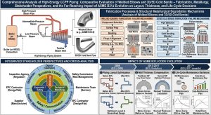
從現場施作實務觀察,1.5D 銲接彎頭的工序極度繁瑣且容錯率極低。施工包含精確的切割、開坡口與對位銲接;且針對 P91 等高能管線,銲接全程必須維持至少 204°C 的預熱溫度24。銲接完成後,為防範氫致冷裂紋,需立即執行 300°C 至 350°C 的氫烘烤程序,再待其冷卻至馬氏體轉變溫度(96°C 以下),最終方能實施漫長且極其嚴苛的 PWHT(730°C 至 760°C)。在這些階段中,一旦遭遇電力中斷或溫度監控失準,極易導致局部結構奧氏體化或殘留脆性組織,導致整顆彎頭或整道銲口報廢28。 From field practice observations, the procedures for 1.5D welded elbows are highly cumbersome with an extremely low margin for error. Construction involves precise cutting, beveling, and alignment welding; for HEP like P91, a minimum preheat of 204°C must be maintained throughout welding24. After welding, to prevent hydrogen-induced cold cracking, an immediate 300°C–350°C hydrogen bake-out must be performed, followed by cooling to the martensite finish temperature (below 96°C), before finally executing the lengthy and stringent PWHT (730°C–760°C). During these stages, if a power outage or temperature monitoring failure occurs, it easily results in localized re-austenitizing or retained brittle microstructures, leading to the scrapping of the entire elbow or weld joint28.
相對而言,3D/5D 大半徑冷作彎管採取「以彎代銲」策略,大幅精簡了現場安裝工序。管線製造商會事前採購符合壁厚補償要求(例如 5D 彎管需 1.08 tm)的標準管材35,並在室溫下利用高精度數控(CNC)機台,施加純物理的拉伸與壓縮應力進行彎曲,將應變率精準控制在 5% 至 20% 之間8。成型後,透過感應加熱技術(IH-PBHT)施以精準的 1040°C 至 1080°C 正火與 730°C 至 780°C 回火。此工法自帶高階溫控程序,完全摒除了現場環境變數對接頭品質的干擾,實現了高能管線的「無縫化」。 In contrast, 3D/5D large-radius cold bends adopt a “Bend instead of Weld” strategy, drastically streamlining field installation procedures. Pipe manufacturers procure standard pipes meeting wall thinning compensation requirements (e.g., 1.08 tm for 5D bends) beforehand35. At room temperature, using high-precision CNC machines, pure physical tensile and compressive stresses are applied for bending, accurately controlling the strain rate between 5% and 20%8. Post-forming, induction heating technology (IH-PBHT) applies precise 1040°C–1080°C normalizing and 730°C–780°C tempering. This method features its own advanced temperature control programming, entirely bypassing field environmental variables that interfere with joint quality, achieving “seamlessness” for high-energy piping.
6.2 業主之維護管理及營運決策 / 6.2 Owners’ Maintenance Management and Operational Decision-Making
從電廠業主(Owner)的角度來看,高能蒸汽管線的安全直接關乎全廠營運壽命與穩定營收。歷史經驗顯示,高階合金鋼的銲道潛變損傷極具欺騙性,往往在商轉超過十萬小時後,才會無預警地演變為 Type IV 裂紋8。若採用傳統銲接彎頭,業主必須在每年的歲修計畫中編列鉅額預算,進行搭架、拆卸保溫層,並聘請高階檢測團隊進行 PAUT 追蹤。 From the viewpoint of power plant Owners, the safety of high-energy steam piping directly relates to the entire plant’s operational lifespan and stable revenue. Historical experience reveals that creep damage in high-grade alloy welds is highly deceptive, often devolving without warning into Type IV cracks only after 100,000 hours of commercial operation8. If traditional welded elbows are used, owners must allocate massive budgets in their annual outage plans for scaffolding, insulation removal, and hiring high-tier NDE teams for PAUT tracking.
反之,若在建設初期決策採用 3D/5D 冷作彎管,因其在物理上徹底消除了熱影響區(HAZ),業主便能依據 EPRI 指引與 ASME 規範合法地減少這些高頻率、高成本的進階體積性非破壞檢測(NDE)。這對業主而言不僅是維護管理上的一大解脫,更賦予了電廠對「未漏先破」災難的長期免疫力。 Conversely, if the decision to use 3D/5D cold bends is made during the initial construction phase, since HAZs are physically eliminated, the owner can legally and justifiably reduce these high-frequency, high-cost advanced volumetric NDEs based on EPRI guidelines and ASME codes. This is not only a major relief in maintenance management for the owner, but it also endows the plant with long-term immunity against “break-before-leak” disasters.
6.3 EPC 承包商設計單位之空間佈置與實務考量 / 6.3 Spatial Layout and Practical Considerations for EPC Contractor Design Units
對於負責統包設計的 EPC 團隊而言,必須在 ASME B31.1 約 4.0 的嚴苛安全係數與高溫高壓雙重條件下找出合規的配置1。在 ASME B31J 矩陣解析度提升後,傳統 1.5D 彎頭極易在面外與扭轉方向面臨應力超標的窘境12。 For EPC teams responsible for turnkey designs, they must find compliant layouts under the dual constraints of high temperatures, high pressures, and ASME B31.1’s stringent safety factor of roughly 4.01. With the enhanced resolution of the ASME B31J matrix, traditional 1.5D elbows easily face stress over-limit predicaments in out-of-plane and torsional directions12.
在實務空間佈置上,5D 冷作彎管確實比 1.5D 彎頭佔用更大的幾何迴轉半徑,要求管線佈置工程師必須在 3D 模型建置初期即展開防碰撞與空間餘裕的跨專業協調。然而,5D 彎管所帶來極低的 SIF,能使設計團隊大幅減少為吸收應力而增設的柔性迴圈(Expansion loops)與昂貴的彈簧吊架(Spring hangers),更能實質降低管線對末端設備(如汽輪機)的噴嘴荷重10。此外,5D 彎管僅要求 8% 的壁厚減薄補償,多數市售標準 Schedule 鋼管即可滿足,避免了因採購客製化超厚母管而導致的專案延宕與成本超支8。 In practical spatial layouts, a 5D cold bend indeed occupies a larger geometric turning radius than a 1.5D elbow, requiring piping layout engineers to conduct cross-disciplinary clash-detection and clearance coordination early in 3D modeling. However, the extremely low SIF provided by the 5D bend enables design teams to vastly reduce expansion loops and expensive spring hangers added to absorb stress, tangibly lowering nozzle loads exerted on terminal equipment (like turbines)10. Additionally, the 5D bend requires only an 8% wall thinning compensation, which most off-the-shelf standard Schedule pipes satisfy, avoiding project delays and cost overruns associated with procuring custom extra-heavy parent pipes8.
6.4 廠務管理者之維護與運轉要求 / 6.4 Maintenance and Operational Requirements from Plant Managers’ Perspectives
廠務管理者(Plant Manager)的日常營運重點,在於防範無預警跳機(Forced outages)與流動加速腐蝕(FAC)等系統衰退現象。1.5D 銲接彎頭因其急促的轉角設計,極易在高速蒸汽流過時產生嚴重的流場分離與高強度紊流,反覆剝離管壁內側的氧化層,這使得傳統彎頭成為 FAC 最猖獗的熱點。廠務端必須為此頻繁執行超音波測厚(UT)來監控管壁減薄率。 The daily operational focus of Plant Managers lies in preventing systemic degradation phenomena like forced outages and Flow-Accelerated Corrosion (FAC). Because of their sharp corner designs, 1.5D welded elbows easily generate severe flow separation and high-intensity turbulence when high-speed steam passes through, repeatedly stripping the oxide layer inside the pipe wall. This makes traditional elbows rampant hot spots for FAC. Consequently, plant operators must frequently execute ultrasonic thickness (UT) measurements to monitor wall thinning rates.
透過導入 3D/5D 大半徑冷作彎管,系統獲得了近似層流(Laminar flow)的平滑邊界層,從流體物理機制上拔除了 FAC 熱點34。這種工法的轉變,使得廠務管理者能夠安心地延長檢測週期,將有限的人力與運保(O&M)資源集中於其他更關鍵的核心發電設備上,進而達成電廠妥善率的最優化。 By integrating 3D/5D large-radius cold bends, the system achieves a smooth boundary layer approximating laminar flow, fundamentally uprooting FAC hot spots from a fluid physics standpoint34. This process shift allows Plant Managers to comfortably extend inspection cycles, concentrating limited manpower and Operations & Maintenance (O&M) resources on other more critical core generating equipment, thereby optimizing plant availability.
6.5 冷作彎管施作協力廠商之要求及因應策略 / 6.5 Requirements and Coping Strategies for Cold Bending Subcontractors
面對 EPC 廠商對於 3D/5D 大半徑管線的委託,冷彎施作協力廠商承受著 ASME 規範最嚴格的實體限制。在執行冷彎加工時,協力廠商必須確保高階合金管的幾何外觀不因劇烈應力而過度畸變,其截面橢圓化(Ovality)通常被嚴格要求低於 8%;且若外弧側實際減薄率大於 5%,則強制要求必須執行 100% 的超音波測厚檢驗8。 When entrusted with 3D/5D large-radius piping by EPC firms, cold bending subcontractors bear the strictest physical constraints of the ASME codes. During cold bending, subcontractors must ensure that the high-grade alloy pipe’s geometry does not distort excessively under intense stress. Cross-sectional Ovality is strictly capped, usually below 8%; and if actual extrados thinning exceeds 5%, a mandatory 100% UT thickness check is required8.
為達成此目標,協力商的因應策略必須全面升級:在硬體上需導入高精密的重型 CNC 彎管機,以確保極高強度的成形準確度8;熱處理階段則必須揚棄傳統火烘,全面改採具備數位監控與閉環控制的感應加熱(IH-PBHT)設備,確保 1040°C 至 1080°C 的正火奧氏體化與 730°C 至 780°C 回火的時間與升溫斜率完美契合規範要求。唯有產出無懈可擊的熱處理圖表與硬度檢測報告,協力商才能向業主證明管件的微觀晶格與潛變延展性已獲得完美修復。 To meet these targets, subcontractor strategies must upgrade across the board. In hardware, high-precision heavy-duty CNC bending machines must be introduced to guarantee extremely high-strength forming accuracy8. During heat treatment, traditional fire baking must be discarded in favor of Induction Heating (IH-PBHT) equipment equipped with digital monitoring and closed-loop controls, ensuring the time and ramp slopes for 1040°C–1080°C austenitizing and 730°C–780°C tempering perfectly align with code requirements. Only by producing impeccable heat treatment charts and hardness testing reports can subcontractors prove to owners that the fittings’ microstructural lattices and creep ductility have been perfectly restored.
6.6 實務案例分析:導入潁璋工程「能彎不銲」三合一工法之深度探討 / 6.6 Practical Case Analysis: In-Depth Exploration of Implementing Ying-Zhang Engineering’s “Bend, Don’t Weld” Three-in-One Method
針對實務上高度嚴苛的高能管線佈局,本節將深度探討特定工程實踐——即潁璋工程所提倡之「能彎不銲」設計理念,及其透過獨創的「三合一工法」在複雜 CCPP 專案中的實際落實與合規性檢驗。 Targeting highly demanding high-energy piping layouts in practice, this section delves into specific engineering practices—namely, the “bend, don’t weld” design philosophy advocated by Ying-Zhang Engineering, and its practical implementation and compliance verification in complex CCPP projects through their original “Three-in-One Method.”
6.6.1 三合一工法管理核心價值與「能彎不銲」設計理念落實 / 6.6.1 Management Core Value of the Three-in-One Method and Implementation of “Bend, Don’t Weld”
針對現代 CCPP 嚴苛的營運需求,潁璋工程的「能彎不銲」核心理念,透過其「三合一工法」在實務端獲得了完美的落實。該工法高度整合了「高精度 CNC 3D/5D 冷作彎曲」、「嚴格的壁厚減薄與橢圓化幾何控制」以及「精準的數位感應加熱彎後熱處理 (IH-PBHT)」8。在管理核心價值上,此工法將原本屬於「現場施工與後期維護」的高度不確定性與潛在風險,提前轉移並消弭於「前端工廠預製與材料工程」階段。藉由在物理上徹底抹除高應力區的銲道與熱影響區 (HAZ),該工法不僅直接根絕了 Type IV 潛變破裂的微觀溫床,更使業主在全生命週期管理中,大幅降低了非破壞檢測 (NDE) 的長期追蹤成本與非計畫性跳機的鉅額損失。 Addressing modern CCPPs’ stringent operational needs, Ying-Zhang Engineering’s “bend, don’t weld” core philosophy is perfectly realized practically through their “Three-in-One Method.” This method highly integrates “high-precision CNC 3D/5D cold bending,” “strict wall thinning and ovality geometric controls,” and “precise digital IH-PBHT”8. In terms of core management value, this method proactively shifts and eliminates the high uncertainties and potential risks—originally belonging to “on-site construction and post-maintenance”—into the “front-end shop prefabrication and materials engineering” stage. By physically erasing welds and HAZs in high-stress zones, this method not only eradicates the microscopic hotbeds for Type IV creep rupture but also significantly reduces long-term NDE tracking costs and massive financial losses from forced outages in the owner’s full-lifecycle management.
6.6.2 頻繁起停瞬態下應變率 (5% 至 20%) 放寬與 IH-PBHT 適用性解析 / 6.6.2 Relaxation of Strain Rate (5% to 20%) Under Frequent Start-Stop Transients and IH-PBHT Applicability
現代複循環燃氣機組頻繁起停所引發的巨大溫度梯度與物理瞬態,會在管壁內外產生嚴重的雙軸拉伸應力,並疊加高溫持載形成破壞力極強的 CFI4。在此熱力學循環破壞機制下,傳統 1.5D 銲接彎頭極易於晶界萌生潛變孔洞。然而,冷作彎曲工法在成形時必然伴隨塑性變形。依據理論應變率計算方程式(ϵ=Do/2R1 ×100%),3D 彎管的成形應變率約為 16.7%,而 5D 彎管則為 10.0%8。這兩項關鍵數值皆精準落入 ASME B31.1 與 B31J 針對熱處理所制定的「5% 至 20%」放寬過渡區間內。 The massive temperature gradients and physical transients triggered by frequent start-stops in modern combined cycle gas units create severe biaxial tensile stresses across pipe walls. Compounded by high-temperature dwells, this forms highly destructive CFI4. Under this thermodynamic cyclic damage mechanism, traditional 1.5D welded elbows easily nucleate creep cavities at grain boundaries. However, cold bending inevitably accompanies plastic deformation during forming. Based on the theoretical strain rate formula (ϵ=Do/2R1 ×100%), the forming strain rate for 3D bends is about 16.7%, and for 5D bends, it is 10.0%8. Both key metrics fall perfectly within the “5% to 20%” transitional relaxation window established by ASME B31.1 and B31J for heat treatment.
針對此應變率區間,規範允許透過 IH-PBHT 進行微觀組織的全面重塑。相較於易引發 Laves 相異常粗化與固溶強化失效的次臨界熱處理,潁璋工程嚴格採用「正火加回火」的頂級工法:首先將管件感應加熱至 1040°C 至 1080°C(遠高於上臨界點 AC3)使其完全奧氏體化,藉由高溫原子擴散徹底抹除高達 10% 至 16.7% 的冷彎晶格畸變與差排堆積;隨後於 730°C 至 780°C 進行高溫回火,促使 MX 相與 M23C6 碳化物再次均勻彌散析出。此一重塑過程完美抵禦了 CFI 損傷機制,使高能合金材料恢復甚至超越其原始的潛變延展性。 For this strain rate range, the code permits full microstructural reshaping via IH-PBHT. Compared to subcritical heat treatments that tend to cause abnormal Laves phase coarsening and loss of solid solution strengthening, Ying-Zhang Engineering strictly employs the top-tier “Normalizing & Tempering” process. The fitting is first induction-heated to 1040°C–1080°C (well above AC3) to fully austenitize. Through high-temp atomic diffusion, the 10% to 16.7% cold-bending lattice distortions and dislocation pileups are totally wiped out. Subsequently, high-temp tempering between 730°C and 780°C forces the MX phase and M23C6 carbides to homogeneously re-precipitate. This reshaping process perfectly counters CFI damage mechanisms, allowing the high-energy alloy to recover or even surpass its original creep ductility.
6.6.3 對於 P9x 高能管線之潁璋工程三合一工法合規性驗證 / 6.6.3 Compliance Verification of Ying-Zhang Engineering’s Three-in-One Method for P9x High-Energy Piping
在嚴苛的國際規範框架下,該三合一工法展現了對 P9x (P-No. 15E) 高能管線的絕對合規性。首先,在 ASME B31.1 第 102.4.5 節的壁厚減薄法則中,5D 冷彎工法僅需 8% 的補償餘裕,不僅符合承壓邊界設計要求,更兼顧了原料成本優化,避免了 3D 彎管高達 25% 的特製母管厚度需求8。其次,針對 P9x 材質對化學成分的極度敏感性——特別是 (Mn+Ni) 總量大於 1.0% 時對下臨界點 AC1 溫度的抑制效應——潁璋工程的 IH-PBHT 展現了極高的溫控精度,避免了傳統熱處理因局部過熱導致材料重新奧氏體化而形成脆性「新鮮馬氏體」的致命風險5。 Within the rigorous international code framework, this three-in-one method demonstrates absolute compliance for P9x (P-No. 15E) high-energy piping. First, under ASME B31.1 Section 102.4.5’s wall thinning rules, the 5D cold bend process requires only an 8% compensation allowance. This not only meets pressure boundary design requirements but also balances raw material cost optimization, avoiding the steep 25% custom parent pipe thickness requirement of 3D bends8. Secondly, regarding P9x material’s extreme chemical sensitivity—especially the suppressing effect on AC1 when (Mn+Ni) exceeds 1.0%—Ying-Zhang Engineering’s IH-PBHT demonstrates superb temperature-control precision. This evades the lethal risks in traditional heat treatments where localized overheating induces re-austenitization and forms brittle “fresh martensite”5.
此外,依據 ASME B31J 的 SIF 解耦矩陣,該工法產出的 3D/5D 彎管在面內 (ii)、面外 (io) 與扭轉 (it) 應力強化係數上皆趨近於理想直管的絕對下限 (1.0),徹底免除了傳統銲接彎管在承受 B31.1 WSRF 懲罰性厚壁化後所衍生的系統剛性暴增難題。綜合而論,此三合一工法不僅完全符合 2026 年版 ASME B31.1 (Table 129.3.1-1) 針對 P91 成形後的應變極限與熱處理強制規定,更為高溫高壓動力管線提供了無可挑剔的結構完整性保障8。 Furthermore, based on ASME B31J’s decoupled SIF matrix, the 3D/5D bends produced by this method exhibit in-plane (ii), out-of-plane (io), and torsional (it) SIFs that all approach the absolute lower limit of an ideal straight pipe (1.0). This completely eliminates the skyrocketing system stiffness dilemmas derived from traditional welded elbows suffering B31.1 WSRF thickness penalties. Comprehensively speaking, this three-in-one method is not only fully compliant with the 2026 ASME B31.1 (Table 129.3.1-1) mandatory regulations for post-forming strain limits and heat treatment of P91, but it also provides impeccable structural integrity guarantees for high-temp/high-pressure power piping8.
七、 結論 / VII. Conclusion
本研究透過固體力學、冶金相變機制、流固耦合動力學與國際壓力規範演進之跨領域深度分析,針對 CCPP 高能管線中 1.5D 銲接彎頭與 3D/5D 冷作彎管的施作流程與結構完整性進行了全面性探討,並結合工程實務與多方利害關係人決策,獲致以下重要學術與工程結論: Through an interdisciplinary deep analysis of solid mechanics, metallurgical phase transformation mechanisms, fluid-solid coupling dynamics, and international pressure code evolution, this study comprehensively investigates the fabrication processes and structural integrity of 1.5D welded elbows and 3D/5D cold bends in CCPP high-energy piping. Integrating engineering practice and multi-stakeholder decision-making yields the following critical academic and engineering conclusions:
- ASME B31J 規範顛覆並重塑了管線設計邊界 / ASME B31J Codes Disrupt and Reshape Piping Design Boundaries:2024 至 2026 年強制全面實施的 ASME B31J 規範,徹底揚棄了不合時宜的單一 Markl 疲勞經驗值。新規範引入空間方向性彈性矩陣,將應力強化係數嚴格解耦為面內(ii)、面外(io)與扭轉(it)。在 CAESAR II 等軟體的高解析度檢視下,傳統1.5D 銲接彎頭因極高的扭轉與面外應力集中缺陷,已無法滿足現代高能管線的安全裕度要求。The B31J codes, mandated comprehensively from 2024 to 2026, completely cast away outdated singular Markl fatigue empirical values. The new code introduces spatial directional elasticity matrices, strictly decoupling SIFs into in-plane (ii), out-of-plane (io), and torsional (it) factors. Under high-res scrutiny from software like CAESAR II, traditional 1.5D welded elbows can no longer satisfy modern high-energy piping safety margins due to extremely high torsional and out-of-plane stress concentration defects.
- 銲接彎頭之冶金衰退為系統性硬傷 / Metallurgical Degradation of Welded Elbows is a Systemic Flaw:針對 P91/P92 等高階潛變強度合金,1.5D 彎頭與直管的銲接熱影響區(HAZ)無可避免地會發生不完全奧氏體化,破壞 MX 碳氮化物的齊納釘紮效應。在 CCPP 頻繁啟停所引發的潛變-疲勞交互作用(CFI)下,極易於臨界熱影響區(ICHAZ)誘發隱蔽且致命的 Type IV 潛變裂紋。同時,ASME B31.1 所強制施加的 WSRF 銲接強度折減係數,迫使管件大幅增厚,進一步惡化了系統整體的動態剛性。For high-grade creep-strength alloys like P91/P92, the HAZ between 1.5D elbows and straight pipes unavoidably undergoes incomplete austenitization, destroying the Zener pinning effect of MX carbonitrides. Under the CFI induced by frequent CCPP start-stops, highly concealed and lethal Type IV creep cracks easily nucleate in the Intercritical HAZ (ICHAZ). Simultaneously, the mandatory ASME B31.1 WSRF penalty forces drastic pipe thickening, further deteriorating the system’s overall dynamic stiffness.
- 3D/5D 冷作彎管在流固力學上展現決定性優勢 / 3D/5D Cold Bends Display Decisive Fluid-Solid Mechanics Advantages:冷彎工法完美實現了「以彎代銲」的理念,本體無銲道設計從幾何源頭阻斷了 Type IV 裂紋的萌生途徑。藉由將彎曲半徑擴大至 3D 或 5D,柔性特徵值 h 顯著躍升,使 SIF 急遽衰減並趨近於理想直管。依據 Coffin-Manson 模型,此舉將使疲勞壽命呈指數級別延長。此外,大半徑帶來近似層流的邊界層,更從物理機制上消除了流動加速腐蝕(FAC)的危害。The cold-bending process perfectly realizes the “Bend instead of Weld” concept; the weld-free body design chokes off Type IV crack initiation paths at the geometric source. By expanding the bend radius to 3D or 5D, the flexibility characteristic h jumps significantly, causing SIFs to sharply attenuate and approach those of an ideal straight pipe. Based on the Coffin-Manson model, this exponentially extends fatigue life. Additionally, the large radius brings boundary layers close to laminar flow, physically eliminating Flow-Accelerated Corrosion (FAC) hazards.
- 先進冷彎工法達到工程經濟學與材料科學的最佳化平衡 / Advanced Cold Bending Processes Achieve Optimal Balance Between Engineering Economics and Material Science:依據 ASME B31.1 第4.5 節的壁厚減薄法則,3D 彎管需付出高達 25% 增厚餘裕的代價,導致超厚母管採購困難與成本飆升;而 5D 彎管僅需 8% 的餘裕即可符合承壓邊界要求,絕大多數標準管材即可勝任。配合新規範對成形應變率(5% 至 20%)的科學放寬,實務上(如潁璋工程所提倡之三合一工法)在實施精準的感應加熱彎後熱處理(IH-PBHT)進行組織重塑(正火+回火)後,能在極低的附加成本下,獲取凌駕於銲接彎頭的極高結構安全裕度,無疑將成為未來大型燃氣發電廠高能管線建置的必然標準。According to ASME B31.1 Section 102.4.5’s wall thinning rules, 3D bends incur a hefty 25% extra thickness allowance, causing procurement difficulties and cost spikes for ultra-thick parent pipes. In contrast, 5D bends require only an 8% allowance to meet pressure boundary rules, allowing standard commercial pipes to suffice. Coupled with the new code’s scientific relaxation of forming strain rates (5% to 20%), practical applications (such as Ying-Zhang Engineering’s three-in-one method) implementing precise IH-PBHT (Normalizing + Tempering) for microstructural reshaping can obtain supremely high structural safety margins over welded elbows at very low marginal costs. This will undeniably become the inevitable standard for high-energy piping installations in future large gas-fired power plants.
參考文獻 / References
- What is the ASME B31.1 Power Piping Code and What is New?, https://epcland.com/asme-b31-1-power-piping-code/
- CREEP CRACK GROWTH BEHAVIOR OF P91 STEEL WELDMENTS, https://thermalscience.rs/pdfs/papers-2017/TSCI170729240S.pdf
- 複循環燃氣機組頻繁起停之物理瞬態與熱力學 … – 潁璋工程興業有限公司, https://yz-pipe-bending.com.tw/%E8%A4%87%E5%BE%AA%E7%92%B0%E7%87%83%E6%B0%A3%E6%A9%9F%E7%B5%84%E9%A0%BB%E7%B9%81%E8%B5%B7%E5%81%9C%E4%B9%8B%E7%89%A9%E7%90%86%E7%9E%AC%E6%85%8B%E8%88%87%E7%86%B1%E5%8A%9B%E5%AD%B8%E5%BE%AA%E7%92%B0/
- Stress Intensity Factor (SIF), Flexibility Factor: ASME B31.3 vs ASME, https://whatispiping.com/stress-intensity-factor-sif-flexibility-factor-asme-b-31j/
- 複循環電廠調峰操作下高能管線之疲勞壽命分析 – 潁璋工程興業有限公司, https://yz-pipe-bending.com.tw/%E8%A4%87%E5%BE%AA%E7%92%B0%E9%9B%BB%E5%BB%A0%E8%AA%BF%E5%B3%B0%E6%93%8D%E4%BD%9C%E4%B8%8B%E9%AB%98%E8%83%BD%E7%AE%A1%E7%B7%9A%E4%B9%8B%E7%96%B2%E5%8B%9E%E5%A3%BD%E5%91%BD%E5%88%86%E6%9E%90%EF%BC%9A/
- Recommendation for Creep and Creep-fatigue assessment for P91, https://publications.jrc.ec.europa.eu/repository/bitstream/JRC94508/jrc94508_matter_4-6_creep-fatigue.pdf
- ASME B31J-2023 Overview: Stress Intensification Factor (SIF) and, https://fengshecad.com/795/
- ASME B31.1-2024 Stress Intensification Factors (SIFs) — FAQ, https://pipingtoolset.com/faq/b311-stress-intensification-factors/
- Introduction to ASME B31J Standard – Northern Crescent Inc., https://www.northerncrescent.ca/blog/introduction-to-asme-b31j-standard/
- Stress Intensification Factors (SIFs) in Pipe Stress Analysis, https://simumech.com/stress-intensification-factors-sifs-in-pipe-stress-analysis/
- 基於2026 ASME B31.1 與B31J 規範之複循環發電廠動力管線3D/5D, https://yz-pipe-bending.com.tw/%E5%9F%BA%E6%96%BC-2026-asme-b31-1-%E8%88%87-b31j-%E8%A6%8F%E7%AF%84%E4%B9%8B%E8%A4%87%E5%BE%AA%E7%92%B0%E7%99%BC%E9%9B%BB%E5%BB%A0%E5%8B%95%E5%8A%9B%E7%AE%A1%E7%B7%9A-3d-5d-%E5%86%B7%E4%BD%9C/
- Mastering ASME B31J Piping Stress Analysis for Plant Integrity, https://epcland.com/asme-b31j-piping-stress-analysis/
- 解析2026 ASME B31.1與B31J應變率(5%~20%)放寬與IH-PBHT適用, https://yz-pipe-bending.com.tw/%E8%A7%A3%E6%9E%902026-asme-b31-1%E8%88%87b31j%E6%87%89%E8%AE%8A%E7%8E%87520%E6%94%BE%E5%AF%AC%E8%88%87ih-pbht%E9%81%A9%E7%94%A8%EF%BC%9A%E6%BD%81%E7%92%8B%E5%B7%A5%E7%A8%8B%E5%B0%8D%E6%96%BCp9x/
- Understanding SIF for Piping Elbows | PDF | Stress (Mechanics), https://www.scribd.com/document/961304255/Pipe-ELbow-SIF
- Piping Elbow or Bend SIF (Stress Intensification Factor), https://whatispiping.com/bend-sif/
- Stress Intensification & Flexibility Factor Calculator (B31.3 Appendix D), https://pipingtoolset.com/calculators/b313-stress-intensification-factors/
- 基於ASME B31J (2024-2026) 規範演進之高能管線佈局最佳化, https://yz-pipe-bending.com.tw/%E5%9F%BA%E6%96%BC-asme-b31j-2024-2026-%E8%A6%8F%E7%AF%84%E6%BC%94%E9%80%B2%E4%B9%8B%E9%AB%98%E8%83%BD%E7%AE%A1%E7%B7%9A%E4%BD%88%E5%B1%80%E6%9C%80%E4%BD%B3%E5%8C%96%EF%BC%9A3d-5d-%E5%86%B7%E4%BD%9C/
- ASME B31J Essentials for Piping Analysis | PDF – Scribd, https://www.scribd.com/document/961302630/B31J-Essentials
- SIF, https://sites.google.com/site/fareastpiperreference/analysis/sif
- Asme B31J-2017 | PDF – Scribd, https://www.scribd.com/document/678524069/ASME-B31J-2017
- ASME B31J: I & K Factors in Pipe Analysis, https://www.cortexsoftware.com.au/blog/understanding-asme-b31j-methods-i-factors-and-k-factors-in-piping-stress-analysis
- CAESAR II and START-PROF Differences, https://edu.truboprovod.ru/kbase/doc/start/WebHelp_en/CaesarDiff.htm
- Reducing Elbow – Bentley Software Documentation, https://docs.bentley.com/LiveContent/web/AutoPIPE-v2026/Help/en/Topics/Workbook/wbk_reducing_elbow.html
- Welding P91 Steel: Essential Requirements – WeldFabWorld, https://www.weldfabworld.com/p91-material-requirement/
- 燃氣複循環電廠(CCPP) P9x 級高能高壓管線銲道之綜合分析與微觀潛, https://yz-pipe-bending.com.tw/%E7%87%83%E6%B0%A3%E8%A4%87%E5%BE%AA%E7%92%B0%E9%9B%BB%E5%BB%A0-ccpp-p9x-%E7%B4%9A%E9%AB%98%E8%83%BD%E9%AB%98%E5%A3%93%E7%AE%A1%E7%B7%9A%E9%8A%B2%E9%81%93%E4%B9%8B%E7%B6%9C%E5%90%88%E5%88%86/
- Welding and Postweld Heat Treatment of P91 Steels – ResearchGate, https://www.researchgate.net/publication/291129054_Welding_and_Postweld_Heat_Treatment_of_P91_Steels
- P91 Post Weld Heat Treatment Guidelines | PDF – Scribd, https://www.scribd.com/document/137149894/PWHT-of-P91
- What is P91 welding? – Axiom Heat Treatment, https://axiomht.com/blog/what-is-p91-welding/
- PHASE TRANSFORMATIONS IN CREEP STRENGTH ENHANCED, https://mtmcongress.com/proceedngs/2011/2/03.PHASE%20TRANSFORMATIONS%20IN%20CREEP%20STRENGTH%20ENHANCED%20FERRITIC%20STEEL%20WELDS.pdf
- PWHT Requirements & Processes: Getting it Right is Mission-Critical, https://www.littlepeng.com/single-post/pwht-requirements-processes-getting-it-right-is-mission-critical
- Evaluation of Welded Joints in P91 Steel under Different Heat, https://www.mdpi.com/2075-4701/10/1/99
- Weld Strength Reduction Factors in B31.1 | PDF – Scribd, https://www.scribd.com/doc/283979264/074-7
- ASME B31.1 Wall Thickness Calculator — ¶104.1.2 – Piping Toolset, https://pipingtoolset.com/calculators/b311-pipe-wall-thickness/
- What is Induction Bending? Hot Bending vs. Cold Bending, https://whatispiping.com/induction-bending/
- 現代高能動力管線「以彎代銲」之技術經濟評估:從傳統配管到大, https://yz-pipe-bending.com.tw/%E7%8F%BE%E4%BB%A3%E9%AB%98%E8%83%BD%E5%8B%95%E5%8A%9B%E7%AE%A1%E7%B7%9A%E3%80%8C%E4%BB%A5%E5%BD%8E%E4%BB%A3%E9%8A%B2%E3%80%8D%E4%B9%8B%E6%8A%80%E8%A1%93%E7%B6%93%E6%BF%9F%E8%A9%95%E4%BC%B0%EF%BC%9A/
- Pipe Bend Wall Thickness Calculator — ASME B31.3 ¶304.2.1, https://pipingtoolset.com/calculators/pipe-bend-wall-thickness/
- What is Induction Bending and How Does It Compare? – EPCLand, https://epcland.com/what-is-induction-bending-hot-vs-cold/
- What is Induction Bending? Hot Bending vs. Cold Bending. – PipeTec, https://pipetec.ae/induction-bending/what-is-induction-bending-hot-bending-vs-cold-bending
- Welding Tee SIF Calculator — B31.3 App. D, 2018 & Earlier, https://pipingtoolset.com/calculators/welding-tee-sif/
- The Coffin-Manson Model | Bohrium, https://www.bohrium.com/en/sciencepedia/feynman/keyword/coffin_manson_model
- EPRI Field Guide For Boiler Tube Failures PDF – Corrosion – Scribd, https://www.scribd.com/document/338080649/116379556-EPRI-Field-Guide-for-Boiler-Tube-Failures-pdf
- High-Energy Piping: Where to Inspect? | GlobalSpec, https://insights.globalspec.com/article/2351/high-energy-piping-where-to-inspect
- Significant reduction in creep life of P91 steam pipe elbow caused, https://pmc.ncbi.nlm.nih.gov/articles/PMC10909855/