
摘要 / Abstract
在現代重工業、航太與精密流體控制領域中,高壓油壓管線及製程管線的完整性直接決定了整套設備的運行安全與生命週期成本。傳統管線系統在應對流體轉向需求時,普遍依賴標準 1.5D 鍛造彎頭(Elbow)並輔以多銲道對銲(Butt-welded)進行連接。然而,隨著高壓、高頻壓力脈動以及嚴苛多相流環境的挑戰日益加劇,銲縫與其熱影響區(Heat-Affected Zone, HAZ)逐漸成為引發疲勞裂紋、空穴沖蝕與系統汙染的最薄弱環節。In modern heavy industry, aerospace, and precision fluid control sectors, the integrity of high-pressure hydraulic and process piping directly determines the operational safety and life-cycle cost of the entire equipment. To address fluid redirection needs, traditional piping systems generally rely on standard 1.5D forged elbows connected via multi-pass butt-welding. However, with the increasing challenges of high pressure, high-frequency pressure pulsations, and severe multiphase flow environments, welds and their Heat-Affected Zones (HAZ) have increasingly become the weakest links, prone to initiating fatigue cracks, cavitation erosion, and system contamination.
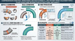
為突破此一工程瓶頸,國際管線工程界正經歷一場深刻的典範轉移,逐步推廣「能彎不銲(Bend Instead of Weld)」之設計方針。本研究旨在以深度學術視角,全面探討傳統 1.0D/1.5D 銲接彎頭與現代數控(CNC)旋繞拉彎成型之 1.5D、3D、5D 冷作彎管在流固耦合與結構力學上的根本性差異。本報告將從製造工法之幾何力學出發,深入剖析狄恩渦流(Dean Vortices)對壓降與紊流的影響,並結合 ASME B31J 規範中應力強化係數(SIF)的解耦理論,評估消除銲道對降低流體誘發振動(FIV)、提升 ISO 4406 系統清潔度及減少洩漏風險的綜合效益。To overcome this engineering bottleneck, the international piping engineering community is undergoing a profound paradigm shift, gradually promoting the “Bend Instead of Weld” design philosophy. This study aims to comprehensively explore the fundamental differences in fluid-structure interaction and structural mechanics between traditional 1.0D/1.5D welded elbows and modern Computer Numerical Control (CNC) rotary draw bent 1.5D, 3D, and 5D cold bends from an in-depth academic perspective. Starting from the geometric mechanics of manufacturing methods, this report analyzes the impact of Dean Vortices on pressure drop and turbulence. Furthermore, integrating the decoupling theory of Stress Intensification Factors (SIF) from the ASME B31J code, it evaluates the comprehensive benefits of eliminating welds in reducing Flow-Induced Vibration (FIV), improving ISO 4406 system cleanliness, and mitigating leakage risks.
一、緒論 / 1. Introduction
管線系統作為工業設備的「血管」,其流體動力效率與結構可靠度至關重要。長期以來,管系佈局中的轉向組件多採用標準規格的鍛造彎頭,透過鎢極氬弧銲(GTAW)等銲接工法與直管段相連。這種傳統工法雖在工業界行之有年,卻不可避免地引入了材料微觀組織的變異與幾何不連續性。銲接過程產生的高溫熔池在快速冷卻後,會於銲縫兩側形成熱影響區,該區域常伴隨晶粒粗大化與韌性下降,成為微裂紋萌生的溫床。此外,內壁的銲根凸起(Weld Root Protrusion)與銲渣,不僅破壞了流體的層流邊界層,更成為微粒汙染的來源。 As the “blood vessels” of industrial equipment, the fluid dynamic efficiency and structural reliability of piping systems are of paramount importance. For a long time, directional components in piping layouts have mostly utilized standard-specification forged elbows connected to straight pipes via welding methods such as Gas Tungsten Arc Welding (GTAW). Although this traditional method has been practiced in the industry for years, it inevitably introduces variations in the material’s microstructure and geometric discontinuities. The high-temperature weld pool generated during welding cools rapidly, forming a Heat-Affected Zone (HAZ) on both sides of the weld. This zone is often accompanied by grain coarsening and reduced toughness, acting as a breeding ground for microcracks. In addition, inner wall weld root protrusions and welding slag not only disrupt the fluid’s laminar boundary layer but also serve as sources of particulate contamination.
隨著 2026 年版 ASME B31J 規範即將全面強制導入,高能管線的應力分析與組件評估標準發生了重大變革。新規範透過更為嚴謹的有限元素分析(FEA)重新定義了應力強化係數,揭示了傳統銲接彎頭在承受面內、面外與扭轉負載時的潛在風險,同時凸顯了大半徑冷作彎管在應力解耦上的卓越優勢。在此背景下,「能彎不銲」不再僅是一項節省工時的製造建議,而是提升高溫、高壓流體系統結構完整性的核心設計哲學。本研究將透過流體力學與固體力學的跨領域探討,系統性地比較這兩種管線轉向工法的優劣,為新一代高壓油壓系統的設計與維護提供堅實的理論與數據基礎。 With the imminent mandatory implementation of the 2026 edition of the ASME B31J code, the standards for stress analysis and component evaluation of high-energy piping have undergone significant changes. Through more rigorous Finite Element Analysis (FEA), the new code redefines the stress intensification factors, revealing the potential risks of traditional welded elbows under in-plane, out-of-plane, and torsional loads, while highlighting the exceptional advantages of large-radius cold bends in stress decoupling. In this context, “Bend Instead of Weld” is no longer just a manufacturing suggestion for saving labor hours, but a core design philosophy for enhancing the structural integrity of high-temperature, high-pressure fluid systems. Through interdisciplinary exploration of fluid mechanics and solid mechanics, this study will systematically compare the pros and cons of these two piping redirection methods, providing a solid theoretical and empirical foundation for the design and maintenance of next-generation high-pressure hydraulic systems.
二、傳統銲接彎頭與 CNC 冷作彎管之實務工法與力學機制 / 2. Practical Construction Methods and Mechanical Mechanisms of Traditional Welded Elbows and CNC Cold Bends
管線組件的成型歷程決定了其最終的幾何連續性與材料特性。要評估彎管在流體與結構上的表現,必須先深入理解其製造工法背後的塑性變形機制與規範限制。The forming history of piping components determines their ultimate geometric continuity and material properties. To evaluate the fluid and structural performance of bends, one must first deeply understand the plastic deformation mechanisms and code constraints behind their manufacturing methods.
2.1 傳統多銲道對銲彎頭的冶金與幾何侷限 / 2.1 Metallurgical and Geometric Limitations of Traditional Multi-Pass Butt-Welded Elbows
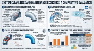
傳統大管徑工法多採用 ASME B16.9 規範的 1.5D 鍛造彎頭,其優點在於標準化程度高且佔用空間小。然而,將彎頭與直管透過多銲道對銲連接,從冶金學角度而言,等同於在管線系統中人為引入了多個材料異質區。銲接時的熱循環會引發相變,熱影響區的硬度通常會顯著高於母材,而斷裂韌性則相對較低。在反覆的壓力脈動下,這些區域極易產生駐留滑移帶(Persistent Slip Bands, PSBs),進而演變為微裂紋。 Traditional large-diameter methods typically utilize 1.5D forged elbows compliant with the ASME B16.9 standard. Its advantages lie in high standardization and a compact footprint. However, from a metallurgical perspective, connecting elbows to straight pipes via multi-pass butt-welding is equivalent to artificially introducing multiple material heterogeneous zones into the piping system. The thermal cycling during welding induces phase transformations, often making the hardness of the HAZ significantly higher than that of the base metal, while its fracture toughness is relatively lower. Under repetitive pressure pulsations, these areas are highly susceptible to developing Persistent Slip Bands (PSBs), which subsequently evolve into microcracks.
在幾何特徵上,即使是最高品質的對銲,也難以保證內壁的絕對平滑。銲道根部的微小凸起或咬邊(Undercut),在高速流體沖刷下會形成局部的應力集中點與流體擾動源。此外,銲接過程中產生的氧化皮與飛濺物若未經徹底的酸洗與湍流沖洗(Turbulent Flow Flushing),將成為系統中極具破壞性的硬質顆粒汙染物。 Geometrically, even with the highest quality butt-welding, absolute smoothness of the inner wall cannot be guaranteed. Minute weld root protrusions or undercuts form localized stress concentration points and sources of fluid disturbance under the scouring of high-speed fluids. Furthermore, if weld scale and spatter generated during the welding process are not thoroughly removed via acid pickling and turbulent flow flushing, they will become highly destructive hard particulate contaminants within the system.
2.2 1.0D 套銲短半徑彎頭之幾何特徵與組裝風險 / 2.2 Geometric Characteristics and Fit-up Risks of 1.0D Short Radius Socket Weld Elbows
針對空間極度受限的管架(Pipe racks)與小管徑(Small Bore Piping)高壓應用,工業界常採用中心線半徑僅為 1 倍公稱管徑的 1.0D 短半徑(Short Radius, SR)套銲(Socket Weld, SW)彎頭1。雖然套銲接頭的抗疲勞能力略優於螺紋接頭,但其設計本質會在管子與套筒之間產生微小的間隙(Crevice)2。 For highly congested pipe racks and Small Bore Piping (SBP) high-pressure applications, the industry frequently employs 1.0D Short Radius (SR) Socket Weld (SW) elbows, where the centerline radius is equal to 1x the nominal pipe diameter1. Although socket weld fittings resist fatigue better than threaded joints, their design inherently creates a small crevice between the pipe and the socket2.
依據 ASME B31.1 與 B31.3 規範,在現場進行套銲組裝時,管子插入套筒底端後必須強制向外退出約 1/16 英吋(1.6 mm)的間隙,以防止管線服役時的熱膨脹應力頂破銲縫根部3。然而,若現場銲工未確實預留此退管間隙,管端將直接觸底,導致銲縫根部在受熱時承受極高的破壞性應力並極易引發裂紋4。此外,該物理間隙亦成為引發間隙腐蝕(Crevice Corrosion)的死角,在某些嚴苛流體服務(如 Category D)中,ASME B31.3 甚至明令禁止使用套銲接頭5。 According to ASME B31.1 and B31.3 codes, during field socket weld fit-up, the pipe must be withdrawn approximately 1/16 inch (1.6 mm) after bottoming out in the socket prior to welding. This gap prevents thermal expansion stresses from cracking the weld root during service3. However, if welders fail to properly maintain this gap, the pipe end will bottom out, subjecting the weld root to highly destructive stresses upon heating and making it extremely susceptible to cracking4. Furthermore, this physical crevice becomes a dead zone prone to crevice corrosion; leading to socket welds being explicitly prohibited in certain severe fluid services (such as Category D) by ASME B31.35.
2.3 現代 CNC 旋繞拉彎(Rotary Draw Bending)之塑性變形機制 / 2.3 Plastic Deformation Mechanism of Modern CNC Rotary Draw Bending
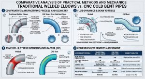
為克服銲接帶來的諸多缺陷,現代工業轉向採用 CNC 旋繞拉彎(Rotary Draw Bending, RDB)技術。該技術能在常溫下使金屬管材沿特定半徑發生塑性變形,一體成型地完成轉向,完全免除了銲道。RDB 系統由五大核心模具協同運作:決定中心線半徑(CLR)的彎曲模(Bend Die)、夾持管段的夾模(Clamp Die)、提供背部支撐與推力的壓模(Pressure Die)、防止內弧起皺的防皺模(Wiper Die)以及防止外弧管壁塌陷的芯棒(Mandrel)。 To overcome the numerous defects associated with welding, modern industry has turned to CNC Rotary Draw Bending (RDB) technology. This technique induces plastic deformation of metal tubing along a specific radius at room temperature, seamlessly completing the directional change as a single piece and completely eliminating welds. The RDB system operates through the coordination of five core tools: the Bend Die determining the Centerline Radius (CLR), the Clamp Die securing the pipe segment, the Pressure Die providing back support and thrust, the Wiper Die preventing wrinkles on the intrados, and the Mandrel preventing the collapse of the extrados wall.
冷彎過程本質上是一場複雜的彈塑性變形。在彎曲力矩作用下,管材的中性軸外側承受拉伸應力,導致外弧(Extrados)管壁減薄;中性軸內側則承受壓縮應力,導致內弧(Intrados)管壁增厚甚至面臨起皺風險。工業界常用兩個無因次參數來評估彎曲難度與缺陷風險:The cold bending process is essentially a complex elastic-plastic deformation. Under the action of the bending moment, the outer side of the pipe’s neutral axis is subjected to tensile stress, causing the extrados wall to thin; the inner side of the neutral axis experiences compressive stress, resulting in intrados wall thickening and a risk of wrinkling. The industry commonly uses two dimensionless parameters to evaluate bending difficulty and defect risks:
- 壁厚係數(Wall Factor, Fw):定義為管外徑與壁厚的比值(Fw = T/W)。Fw 小於 10 代表厚壁管,彎曲穩定性高;當 Fw 大於 30,則屬於薄壁管,極易發生橢圓化(Ovalization)與塌陷,高度依賴防皺模與精密芯棒的支撐。Wall Factor (Fw): Defined as the ratio of the pipe’s outer diameter to its wall thickness (Fw =T/W). An Fw less than 10 indicates a thick-walled pipe with high bending stability; an Fw greater than 30 denotes a thin-walled pipe, highly susceptible to ovalization and collapse, relying heavily on the support of wiper dies and precision mandrels.
- 彎曲緊密度(Degree of Bend, Fd):定義為彎曲中心線半徑與管外徑的比值( Fd = R/T),即常稱的5D、3D 或 5D。數值越小,代表彎曲越劇烈,材料所需的延展性與設備的伺服控制精度要求越高。 Degree of Bend (Fd): Defined as the ratio of the bend centerline radius to the pipe’s outer diameter (Fd = R/T), commonly referred to as 1.5D, 3D, or 5D. A smaller value signifies more severe bending, demanding higher material ductility and servo control precision from the equipment.
2.4 ASME 規範下的幾何公差與回彈(Springback)控制 / 2.4 Geometric Tolerances and Springback Control under ASME Codes
冷作彎管的廣泛應用,必須符合 ASME 規範對幾何變異的嚴格限制。ASME B31.3(製程管線)與 B31.1(動力管線)雖然在安全係數上有所差異,但皆對彎管的橢圓度與減薄率提出了明確要求。對於承受內部壓力的管系,B31.3 規定彎曲後的橢圓度不得超過公稱外徑的 8%,而在外部壓力或真空服務下,限制更為嚴苛,僅允許 3% 的橢圓度。 The widespread application of cold bends must comply with strict geometric variation limits set by ASME codes. Although ASME B31.3 (Process Piping) and B31.1 (Power Piping) differ in safety factors, both establish clear requirements for the ovality and wall thinning rates of bends. For piping systems under internal pressure, B31.3 stipulates that ovality after bending must not exceed 8% of the nominal outer diameter. Under external pressure or vacuum service, the restriction is even more stringent, allowing only 3% ovality.
外弧減薄率(Pt)的預測對於確保設計最小壁厚(tmin)至關重要。其幾何近似公式可表示為:Predicting the extrados wall thinning rate (Pt) is crucial to ensuring the design minimum wall thickness (tmin). Its geometric approximation formula can be expressed as:
Pt=(Ro-R)/Ro =D/2/(R+D/2)
其中 Ro 為彎管外緣半徑,R 為中心線半徑,D 為管外徑。根據實務經驗與理論計算,1.5D 彎管的減薄率可能高達 22%,而當曲率放寬至 3D 時,減薄率約降至 18%,5D 彎管則僅有 12.5%。若減薄後的厚度不滿足 ASME B31.3 第 304.2.1 節的壓力設計公式,設計者必須預先選用更厚的直管來進行彎曲。 Where Ro is the outer edge radius of the bend, R is the centerline radius, and D is the pipe’s outer diameter. According to practical experience and theoretical calculations, the thinning rate for a 1.5D bend can reach up to 22%, whereas relaxing the curvature to 3D reduces the thinning rate to approximately 18%, and for a 5D bend, it is only 12.5%. If the reduced thickness fails to meet the pressure design formula in ASME B31.3 Section 304.2.1, the designer must select a thicker straight pipe in advance for bending.
另一個 CNC 冷彎面臨的挑戰是彈性回彈(Springback)。當模具卸載後,管材因內部殘餘應力的釋放,其最終彎曲角度與半徑會發生偏移。高強度材料的回彈角甚至可達 3.5 度。現代 CNC 彎管機透過預測演算法與線上雷射量測,實施閉迴路的回彈補償控制。系統透過量測初始彎曲後的實際角度,動態調整伺服馬達的過彎(Overbend)設定,將最終角度誤差精準控制在 ±0.05° 至 ±0.25° 之內,確保複雜管系的三維空間佈局完美契合。 Another challenge in CNC cold bending is springback. Upon unloading the tools, the pipe’s final bend angle and radius deviate due to the release of internal residual stresses. For high-strength materials, the springback angle can reach up to 3.5 degrees. Modern CNC bending machines implement closed-loop springback compensation control via predictive algorithms and online laser measurements. By measuring the actual angle after the initial bend, the system dynamically adjusts the servomotor’s overbend setting, precisely controlling the final angular error to within ±0.05° to ±0.25°. This ensures the perfect alignment of complex 3D piping layouts.
三、流體動力性能與局部損失探討:壓降、二次流與沖蝕 / 3. Exploration of Fluid Dynamic Performance and Local Losses: Pressure Drop, Secondary Flow, and Erosion
從流體力學的角度觀之,將 1.0D/1.5D 銲接彎頭改為一體成型的 3D 或 5D 冷作彎管,直接改變了流道的邊界條件與曲率分佈。流體在彎管中的運動狀態極為複雜,涉及強烈的壓力梯度、邊界層分離以及二次流的生成。From the perspective of fluid mechanics, replacing 1.0D/1.5D welded elbows with integrally formed 3D or 5D cold bends directly alters the flow channel’s boundary conditions and curvature distribution. The motion of fluid within bends is highly complex, involving strong pressure gradients, boundary layer separation, and the generation of secondary flows.
3.1 狄恩渦流(Dean Vortices)與二次流力學 / 3.1 Dean Vortices and Secondary Flow Mechanics
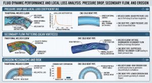
當流體由直管段進入彎曲管段時,受到強大的離心力作用,管腔橫截面上會建立起徑向壓力梯度。靠近管中心的流體因流速較高,所受離心力較大,被強制推向外弧壁面;而靠近管壁的邊界層流體因黏滯力流速較慢,離心力不足以抵抗徑向壓力梯度,於是沿著管壁向內弧回流。這種垂直於主流方向的橫向流動,形成了兩股對稱且反向旋轉的螺旋狀渦流,被稱為二次流(Secondary Flow)或狄恩渦流(Dean Vortices)。 As fluid enters a bent section from a straight pipe, it is subjected to strong centrifugal forces, establishing a radial pressure gradient across the pipe’s cross-section. Fluid near the pipe’s center, moving at a higher velocity, experiences greater centrifugal force and is forced toward the extrados wall; conversely, boundary layer fluid near the wall moves slower due to viscous forces, lacking sufficient centrifugal force to resist the radial pressure gradient, and thus flows back along the wall toward the intrados. This transverse flow, perpendicular to the main flow direction, forms two symmetrical, counter-rotating spiral vortices known as Secondary Flow or Dean Vortices.
二次流的強度與流動的不穩定性,可透過無因次參數「狄恩數(Dean Number, De)」來精確表徵。其數學定義為:The intensity and flow instability of secondary flows can be accurately characterized by a dimensionless parameter called the Dean Number (De). Its mathematical definition is:
De=Re√D/2Rc
其中 Re 為主軸方向的雷諾數,D 為水力直徑,Rc 為彎曲中心線半徑。從方程式中可見,曲率半徑 Rc 越小(如 1.0D 或 1.5D 彎頭),狄恩數越大,二次流的強度與動能耗散越劇烈。強烈的狄恩渦流會扭曲主流速度剖面,使其從直管中對稱的拋物線分佈,轉變為偏向外弧的「駱駝背」雙峰分佈。在傳統小曲率彎頭中,高狄恩數導致紊流邊界層迅速剝離,在內弧下游形成廣闊的尾跡分離區(Separation Zone),將流體的動能大量轉化為熱能與渦漩耗散。相反地,採用 3D 或 5D 大半徑冷彎管,因曲率緩和,狄恩數大幅降低,流動分離現象被有效抑制,流場維持相對穩定的發展狀態。 Where Re is the Reynolds number in the main axial direction, D is the hydraulic diameter, and Rc is the bend centerline radius. As the equation shows, a smaller radius of curvature Rc (such as in a 1.0D or 1.5D elbow) results in a larger Dean Number, leading to more intense secondary flows and kinetic energy dissipation. Strong Dean Vortices distort the mainstream velocity profile, shifting it from a symmetrical parabolic distribution in straight pipes to a “camel-back” bi-peak distribution skewed toward the extrados. In traditional tight-radius elbows, the high Dean Number causes the turbulent boundary layer to rapidly detach, forming a broad wake separation zone downstream of the intrados, which heavily converts fluid kinetic energy into heat and vortex dissipation. Conversely, using 3D or 5D large-radius cold bends smooths the curvature, significantly lowering the Dean Number, effectively suppressing flow separation, and allowing the flow field to maintain a relatively stable development state.
3.2 壓力降與伊藤公式(Ito’s Formula)之理論分析 / 3.2 Theoretical Analysis of Pressure Drop and Ito’s Formula
管系中的總水頭損失(Total Head Loss)主要由直管沿程摩擦損失與彎管局部損失(Minor Loss)構成。彎管造成的額外壓力降 ΔPloss 可透過局部損失係數 K(或稱 ζ)來量化,其關係式為:The Total Head Loss in a piping system mainly consists of major friction losses along straight pipes and Minor Losses in bends. The additional pressure drop ΔPloss caused by a bend can be quantified by the loss coefficient K (or ζ), with the relationship:
ΔPloss=K⋅(ρv2)/2
其中 ρ 為流體密度,v 為平均流速。對於圓截面彎管中的紊流壓力降,伊藤(Ito, 1960)進行了經典的實驗與半經驗公式推導,證實了損失係數 K 與相對曲率半徑(R/r,即2R/D)及雷諾數的非線性關係。 Where ρ is the fluid density and v is the average velocity. For turbulent pressure drops in circular cross-section bends, Ito (1960) conducted classic experiments and semi-empirical formula derivations, confirming the non-linear relationship between the loss coefficient K, the relative radius of curvature (R/r, or 2R/D), and the Reynolds number.
伊藤公式指出,對於不同曲率半徑的彎管,其摩擦係數與損失係數存在顯著差異。實驗數據明確顯示,1.0D 短半徑彎頭因轉向空間被極度壓縮,其壓力降與形狀阻力(Form Drag)顯著高於 1.5D 長半徑彎頭1。而當半徑擴展至 3D 甚至 5D 時,流動依附於管壁的過渡更加平順,K 值可急遽下降至 0.2~0.7 的低阻力區間。計算流體力學(CFD)模型進一步證實,透過拉伸彎曲半徑來優化幾何輪廓,可使彎管的總熵產大幅減少 53% 以上。更值得注意的是,套銲彎頭內部的退管間隙死角與對銲彎頭的銲根凸起,皆會干擾黏性次層(Viscous Sublayer),觸發早期的邊界層分離。反觀 CNC 冷作彎管極度光滑的內壁,從物理源頭上排除了銲縫擾流。 Ito’s formula indicates that for bends with different radii of curvature, friction factors and loss coefficients vary significantly. Experimental data clearly show that 1.0D SR elbows exhibit significantly higher pressure drops and form drag than 1.5D LR elbows due to the extremely compressed turning space1. When the radius is extended to 3D or even 5D, flow attachment to the wall transitions much more smoothly, and the K value sharply drops into a low-resistance range of 0.2 to 0.7. Computational Fluid Dynamics (CFD) models further verify that optimizing the geometric profile by stretching the bend radius can drastically reduce the bend’s total Entropy Generation by over 53%. It is also noteworthy that the withdrawal gap dead zones in socket weld elbows and the weld root protrusions in butt-welded elbows both interfere with the viscous sublayer and trigger early boundary layer separation. Conversely, the exceptionally smooth inner wall of CNC cold bends eliminates weld-induced turbulence at its physical source.
| 管線轉向幾何參數 / Piping Turn Geometry | D 之倍數 (曲率半徑) / Multiple of D (Bend Radius) | 典型 K 值 / Typical K Value (Loss Coefficient) | 狄恩數 (De) 變化趨勢 / Dean Number Trend | 二次流特徵 / Secondary Flow Characteristics |
| 1.0D 套銲短半徑彎頭 / 1.0D SR Socket Weld Elbow | 1.0D | > 1.50(最高 / Highest) | 劇烈 / Extreme | 極強烈流動分離,死角易積存微粒 / Extremely severe flow separation, dead zones trap particles1 |
| 傳統對銲長半徑彎頭 / Traditional Butt-Welded LR Elbow | 1.5D | ≈1.50 | 極高 / Extremely High | 強烈流動分離,渦流耗散大 / Severe flow separation, high vortex dissipation |
| 中半徑冷彎管 / Medium-Radius Cold Bend | 3.0D | ≈0.40~0.70 | 中等 / Moderate | 流動分離受控,壓降顯著降低 / Controlled separation, significant pressure drop reduction |
| 大半徑冷彎管 / Large-Radius Cold Bend | 5.0D | ≈0.20~0.35 | 較低 / Lower | 層流次層穩定,幾乎無流動剝離 / Stable viscous sublayer, almost no flow separation |
3.3 固體微粒沖蝕(Erosion)與空穴(Cavitation)破壞 / 3.3 Solid Particle Erosion and Cavitation Damage
在液壓油系統及輸送多相流體管線中,高速流體挾帶的固體微粒會對管壁造成嚴重的沖蝕破壞。採用 VOF-DEM(Volume of Fluid – Discrete Element Method)的 CFD 模擬研究揭示了微粒在彎管內的軌跡特徵。在 1.0D/1.5D 彎頭中,流向在極短距離內劇烈改變,導致微粒以較大且集中的入射角撞擊外弧大約 60° 至 90° 的區域,造成極高的局部沖蝕率。相對地,將曲率半徑提升至 3D 或 5D 的冷作彎管,微粒多以小角度的「滑擦(Sliding/Rubbing)」方式通過外弧,這種切線方向的動能釋放大幅降低了局部的侵蝕梯度。 In hydraulic oil systems and multiphase fluid transport pipelines, solid particles carried by high-speed fluids cause severe erosive damage to pipe walls. CFD simulation studies using the Volume of Fluid – Discrete Element Method (VOF-DEM) have revealed the trajectory characteristics of particles within bends. In 1.0D/1.5D elbows, the flow direction changes drastically over a very short distance, causing particles to impact the extrados at large and concentrated incidence angles, roughly in the 60° to 90° region, resulting in extremely high localized erosion rates. In contrast, increasing the radius of curvature to 3D or 5D cold bends allows particles to mostly pass the extrados with small-angle “sliding/rubbing” motions. This tangential release of kinetic energy dramatically lowers local erosion gradients.
另外,銲接彎頭內壁的銲根凸起在流體高速掠過時,會在其下游引發局部低壓區,導致空穴氣泡(Cavitation bubbles)析出,產生高達數千大氣壓的微射流(Micro-jets)引發孔蝕。消除銲道的冷彎管因流道連續光滑,從根本上解決了空穴破壞的隱患。 Additionally, when fluid passes over the inner weld root protrusions of welded elbows at high speeds, localized low-pressure zones are induced downstream. This leads to the formation of cavitation bubbles, which, upon collapse, generate micro-jets producing thousands of atmospheres of pressure, causing pitting erosion. Cold bends, free of welds and featuring continuous, smooth flow channels, fundamentally resolve the hidden dangers of cavitation damage.
四、結構可靠度與完整性評估:消除銲道與熱影響區之關鍵效益 / 4. Structural Reliability and Integrity Assessment: Key Benefits of Eliminating Welds and HAZ
流體動力性能的提升有助於降低能耗,但對高壓系統而言,結構可靠度與疲勞壽命更是安全營運的底線。高壓管線長期暴露於壓力脈衝與機械振動中,任何結構弱點都可能導致災難性後果。Enhancing fluid dynamic performance helps reduce energy consumption, but for high-pressure systems, structural reliability and fatigue life serve as the absolute baseline for safe operation. High-pressure piping is continuously exposed to pressure pulsations and mechanical vibrations, where any structural weakness could lead to catastrophic consequences.
4.1 熱影響區(HAZ)消除與高周波疲勞(HCF)壽命提升 / 4.1 HAZ Elimination and High-Cycle Fatigue (HCF) Life Extension
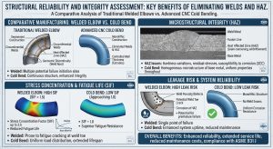
振動誘發疲勞(Vibration-Induced Fatigue)是油氣與液壓管線最主要的失效模式之一。在傳統多銲道結構中,銲趾(Weld Toe)與銲根具有極高的幾何應力集中係數。更致命的是,銲接熱循環使熱影響區(HAZ)發生相變,產生脆硬組織,交變應變極易在 HAZ 集中並形成駐留滑移帶(PSBs),進而快速核化為表面微裂紋。實務界統計,超過 80% 的管線疲勞破裂事故起源於銲縫區域。 Vibration-Induced Fatigue is one of the primary failure modes in oil, gas, and hydraulic piping. In traditional multi-pass welded structures, weld toes and weld roots possess extremely high geometric stress concentration factors. More lethally, welding thermal cycles cause phase transformations in the Heat-Affected Zone (HAZ), producing brittle and hard microstructures. Alternating strains easily concentrate in the HAZ to form Persistent Slip Bands (PSBs), which rapidly nucleate into surface microcracks. Industry statistics show that over 80% of piping fatigue rupture incidents originate in the weld regions.
「能彎不銲」工法保留了金屬母材(Base Metal)連續且穩定的晶格結構,徹底根除了 HAZ 的脆化風險。在嚴苛工況下,ASME B31.3 規範允許透過彎後熱處理(PBHT)來釋放殘餘應力。對於碳鋼與合金鋼,若彎曲引起的最大纖維伸長率超過基礎伸長率的 50%,需強制實施 PBHT,確保抗應力腐蝕開裂(SCC)及疲勞抵抗力達標。 The “Bend Instead of Weld” method preserves the continuous and stable lattice structure of the Base Metal, thoroughly eradicating the embrittlement risk of the HAZ. Under severe service conditions, the ASME B31.3 code permits Post-Bend Heat Treatment (PBHT) to relieve residual stresses. For carbon and alloy steels, if the maximum extreme fiber elongation induced by bending exceeds 50% of the specified minimum elongation, PBHT is mandatory to ensure adequate resistance against Stress Corrosion Cracking (SCC) and fatigue.
4.2 ASME B31J 規範強制化與應力強化係數(SIF)解耦優勢 / 4.2 Mandatory ASME B31J Code and the Decoupling Advantages of Stress Intensification Factors (SIF)
為了量化組件的應力集中程度,ASME 引入了應力強化係數(SIF)。隨著 2026 年版 ASME B31J 規範的全面強制導入,管線應力分析正式邁入精確解耦(Decoupling)時代。 To quantify the degree of stress concentration in components, ASME introduced the Stress Intensification Factor (SIF). With the upcoming mandatory implementation of the 2026 edition of the ASME B31J code, piping stress analysis formally enters an era of precise decoupling.
ASME B31J 利用現代 FEA 重新定義了管件在承受面內(ii)、面外(io)與扭轉(it)彎矩時的 SIF。傳統 1.5D 銲接彎頭因其曲率極大且帶有銲縫,其 SIF 數值居高不下。特別是針對小管徑常用的 1.0D 套銲彎頭,ASME B31J 賦予了其極高的 SIF 數值,主因在於其缺乏全滲透銲(Lack of full penetration)以及結構內部必然存在的微小間隙,這使其在高周波疲勞(High-cycle fatigue)環境下成為最易失效的應力集中熱點3。 Using modern FEA, ASME B31J redefines the SIFs for components subjected to in-plane (ii), out-of-plane (io), and torsional (it) bending moments. Traditional 1.5D welded elbows retain stubbornly high SIF values due to their extreme curvature and the presence of welds. In particular, for 1.0D socket weld elbows commonly used in small bore piping, ASME B31J assigns extremely high SIF values. This is primarily due to the lack of full penetration and the inevitable small crevice within the structure, which makes it the most failure-prone stress concentration hotspot in high-cycle fatigue environments3.
反觀 3D 與 5D 數控冷作彎管,其面內、面外與扭轉 SIF 數值皆急遽下降,逼近理想直管的絕對理論下限值(1.0)。在諸如 AutoPIPE 或 CAESAR II 等應力分析軟體中,極低的 SIF 意味著柔性係數(Flexibility Factor)的提升,賦予了管線工程師在佈局設計上極大的自由度與安全性。 Conversely, 3D and 5D CNC cold bends see their in-plane, out-of-plane, and torsional SIF values drop precipitously, approaching the absolute theoretical limit of an ideal straight pipe (1.0). In stress analysis software such as AutoPIPE or CAESAR II, extremely low SIFs translate to higher Flexibility Factors, granting piping engineers immense freedom and safety in layout design.
五、系統清潔度與維護經濟性效益之評估 / 5. Assessment of System Cleanliness and Maintenance Economic Benefits
「能彎不銲」方針對高壓油壓系統生命週期成本(LCC)的貢獻,突出表現在系統清潔度的確保與洩漏風險的阻絕。The contribution of the “Bend Instead of Weld” approach to the Life-Cycle Cost (LCC) of high-pressure hydraulic systems is highlighted by ensuring system cleanliness and eliminating leakage risks.
5.1 ISO 4406 系統清潔度與伺服閥壽命保障 / 5.1 ISO 4406 System Cleanliness and Servo Valve Life Protection
現代高壓液壓系統普遍配備極度精密的比例閥與伺服閥,對固體微粒汙染具有「零容忍」特性,要求液壓油清潔度必須達到 ISO 4406 15/13/10 或 NAS 1638 Class 6 的極高標準。 Modern high-pressure hydraulic systems are generally equipped with highly precise proportional and servo valves that exhibit a “zero-tolerance” characteristic toward solid particle contamination. This requires hydraulic fluid cleanliness to meet exceptionally high standards, such as ISO 4406 15/13/10 or NAS 1638 Class 6.
現場銲接彎頭會使管內壁產生大量氧化皮(Weld Scale)與銲渣。為清除這些汙染物,新完工的銲接管系必須耗費數週時間進行高流速湍流沖洗(Turbulent Flushing)與酸洗作業。無銲接的冷作彎管在常溫下成型,完全避免了高溫熱源侵入與氧化物生成,使系統在初次建置時的沖洗時間縮短 70% 以上,確保了昂貴液壓組件的長效穩定運作。 Field welding of elbows generates massive amounts of weld scale and slag on the inner pipe walls. To remove these contaminants, newly completed welded piping systems must undergo weeks of high-velocity Turbulent Flushing and acid pickling operations. Weld-free cold bends, formed at room temperature, completely prevent high-temperature heat intrusion and oxide generation. This reduces initial system flushing time by over 70% during construction, ensuring the long-term stable operation of expensive hydraulic components.
5.2 消除洩漏風險與生命週期成本(LCC)優化 / 5.2 Elimination of Leakage Risks and Life-Cycle Cost (LCC) Optimization
傳統銲接工法需要耗費大量高時薪的持證銲工進行作業,且銲後必須執行昂貴的非破壞性檢測(NDT,如射線探傷 RT 或超音波檢測 UT)以確保無內部缺陷。採用冷彎管直接省去了上述所有高耗時與高檢驗成本的環節。在長達數十年的營運階段,冷彎管無銲道設計徹底消除了因疲勞裂紋造成的微小滲漏,零洩漏(Leak-free)的運作不僅節省了清理成本,更杜絕了公安與環保風險,在生命週期成本上展現了壓倒性的優勢。 Traditional welding methods require numerous certified welders at high hourly rates, and expensive Non-Destructive Testing (NDT, such as Radiographic Testing RT or Ultrasonic Testing UT) must be performed post-weld to ensure the absence of internal defects. Adopting cold bends completely bypasses all the aforementioned time-consuming and high-inspection-cost steps. Over decades of operation, the weld-free design of cold bends completely eradicates minor seepages caused by fatigue cracks. Such Leak-Free operation not only saves cleanup costs but also precludes public safety and environmental risks, showcasing an overwhelming advantage in life-cycle cost optimization.
六、產業鏈利害關係人實務探討與工法導入效益 / 6. Practical Perspectives of Supply Chain Stakeholders and Benefits of Method Implementation
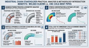
高壓管線系統工程的決策,牽涉到從前端設計、施工建置到後端營運的多方利害關係人。針對 1.5D 銲接彎頭與 1.5D/3D/5D 冷作彎管的實務選擇,各方均面臨著不同的技術瓶頸與經濟考量。本章將極度深入剖析各環節的實務痛點,並探討導入「潁璋工程(Ying-Zhang Engineering)」提倡之「三合一工法」的核心價值與合規性。Decisions in high-pressure piping system engineering involve multiple stakeholders, spanning from front-end design and construction to back-end operations. Regarding the practical choice between 1.5D welded elbows and 1.5D/3D/5D cold bends, each party faces distinct technical bottlenecks and economic considerations. This chapter provides a deeply analytical breakdown of the practical pain points across various stages, while exploring the core value and compliance of the “Three-in-One Method” advocated by Ying-Zhang Engineering.
6.1 業主的維護管理及營運決策考量 / 6.1 Owner’s Considerations for Maintenance Management and Operational Decisions
對於石化廠或發電廠(如 CCPP)的業主而言,管線系統的決策核心在於「生命週期成本(LCC)」極小化與「非預期停機(Unplanned Downtime)」風險的規避。傳統管系因充斥大量銲道,業主在建廠初期需負擔龐大的 NDT(非破壞性檢測,如 RT/UT)檢驗成本;進入營運期後,銲道帶來的熱影響區(HAZ)更是高周波疲勞與應力腐蝕開裂的定時炸彈。 For owners of petrochemical plants or power plants (e.g., Combined Cycle Power Plants, CCPP), the core of piping system decisions revolves around minimizing the Life-Cycle Cost (LCC) and evading risks of Unplanned Downtime. Due to the abundance of welds in traditional piping, owners bear immense NDT (like RT/UT) inspection costs during the initial plant construction phase. Once in the operational phase, the HAZ associated with welds acts as a ticking time bomb for high-cycle fatigue and stress corrosion cracking.
在營運決策上,業主對於系統初次啟動前的管線沖洗(Flushing)時程極為敏感。銲接管內殘留的氧化皮與銲渣,往往使得液壓系統難以迅速達到 ISO 4406 的嚴格潔淨度標準,延宕了整體試車進度。因此,業主端近年強烈傾向採用「能彎不銲」方針,直接免除購買彎頭物料的成本,省去動火管制與銲道檢驗費用,並從根本上消除洩漏導致的公安與環保風險。 Operationally, owners are extremely sensitive to the timeline for piping flushing prior to the system’s initial startup. Residual weld scale and slag in welded pipes often make it difficult for hydraulic systems to quickly meet the stringent ISO 4406 cleanliness standards, delaying the overall commissioning schedule. Therefore, in recent years, owners have shown a strong inclination toward the “Bend Instead of Weld” approach, eliminating the material cost of purchasing elbows, bypassing hot work permits and weld inspection fees, and fundamentally eradicating safety and environmental risks caused by leaks.
6.2 EPC 承包商設計單位之空間佈置與實務考量 / 6.2 Spatial Layout and Practical Considerations for EPC Contractor Design Units
國際 EPC(Engineering, Procurement, Construction)統包商的設計單位在進行管系空間佈置時,面臨著日益嚴苛的應力計算挑戰。在 2026 年 ASME B31J 全面強制導入後,傳統短半徑彎頭的應力強化係數(SIF)大幅攀升。這導致原本可行的佈局在應力分析軟體(如 CAESAR II 或 AutoPIPE)中頻頻呈現應力超標,迫使設計師必須不斷增加複雜的彈簧吊架(Spring Hangers)或擴張熱膨脹環(Expansion Loops)以釋放應力。 Design units of international EPC (Engineering, Procurement, and Construction) contractors face increasingly stringent stress calculation challenges when laying out piping spaces. With the mandatory roll-out of ASME B31J in 2026, the SIF for traditional short-radius welded elbows climbs drastically. This causes previously viable layouts to frequently exhibit stress overloads in analysis software (like CAESAR II or AutoPIPE), forcing designers to continuously add complex spring hangers or expansion loops to relieve stress.
改採 3D/5D 數控冷作彎管,成為 EPC 突破空間限制的關鍵利器。由於 5D 彎管的 SIF 幾近於 1.0(等同直管受力),在 CAESAR II 模型中展現出極佳的柔性餘裕。這賦予了配管工程師在廠房狹小空間中「截彎取直」的佈局自由度,不僅大幅簡化了走線,減少了支撐鋼構的用量,更消減了為應付假性應力超標而投入的無謂成本。 Switching to 3D/5D CNC cold bends becomes a crucial tool for EPCs to overcome spatial constraints. Because the SIF of a 5D bend is near 1.0 (equivalent to the stress on a straight pipe), it exhibits excellent flexibility margins in CAESAR II models. This grants piping engineers the freedom to “straighten curves” within the confined spaces of plant facilities. It not only greatly simplifies routing and reduces structural steel support usage but also eliminates the wasteful costs incurred to manage the pseudo-stress overloads of tight elbows.
6.3 廠務管理者對高壓管線之要求與痛點 / 6.3 Demands and Pain Points of Facility Managers Regarding High-Pressure Piping
廠務與維護管理者處於對抗管線失效的最前線,其最大的痛點在於高頻振動引發的疲勞破裂,特別是在機械設備(如泵浦、壓縮機)周邊的管線。流體誘發紊流(FIT)與聲學誘發振動(AIV)會持續在管壁產生交變應力。當廠務人員依據 Energy Institute (EI) AVIFF 準則進行檢測時,往往發現帶有銲道的轉折處其「失效可能性(Likelihood of Failure, LOF)」居高不下。 Facility and maintenance managers stand on the front lines against piping failures. Their greatest pain point lies in fatigue ruptures triggered by high-frequency vibrations, especially in piping surrounding rotating equipment (e.g., pumps, compressors). Flow-Induced Turbulence (FIT) and Acoustic-Induced Vibration (AIV) continuously produce alternating stresses on the pipe walls. When facility personnel conduct inspections based on the Energy Institute (EI) AVIFF guidelines, they frequently find that directional changes with welds exhibit stubbornly high “Likelihood of Failure” (LOF) values.
傳統作法中,廠務管理者只能透過加裝補強肋板(Gussets)或各類阻尼支架來被動壓制管線的自然頻率(MNF),治標而不治本。因此,從廠務維護的視角出發,極度渴求在源頭端即採用「無銲道冷彎」的管件,將原本應力集中的銲趾與脆弱的 HAZ 徹底移除,換取免維護且具備無限疲勞壽命的本質安全環境。 In traditional practice, facility managers can only passively suppress the Mechanical Natural Frequency (MNF) of the piping by adding reinforcing gussets or various damping supports, addressing the symptoms rather than the root cause. Therefore, from a facility maintenance perspective, there is an intense desire to adopt “weld-free cold bent” piping components directly at the source. This completely removes the stress-concentrating weld toes and fragile HAZ, exchanging them for a maintenance-free, inherently safe environment with infinite fatigue life.
6.4 冷作彎管協力廠商之要求與因應策略 / 6.4 Demands and Response Strategies of Cold Bending Subcontractors
要實現 EPC 與業主的期望,冷作彎管協力廠商面臨著極高的製造門檻。ASME B31.3 對於彎管的減薄率(Wall Thinning)與橢圓度(Ovality,內壓 8%、外壓 3%)設有嚴格的極限值。特別是在處理高強度合金管材或薄壁管(高 Fw值)時,容易發生內弧起皺與外弧塌陷。此外,金屬材料卸載後的彈性回彈(Springback)亦考驗著加工精度。 To fulfill the expectations of EPCs and owners, cold bending subcontractors face a very high manufacturing threshold. ASME B31.3 enforces strict limits on wall thinning and ovality (8% for internal pressure, 3% for external pressure) for bends. Especially when processing high-strength alloy tubing or thin-walled pipes (high Fw values), intrados wrinkling and extrados collapse easily occur. Moreover, the elastic springback of metal materials upon unloading severely tests machining precision.
為此,先進的協力廠商必須捨棄傳統手工或簡易液壓設備,全面升級至大型 CNC 旋繞拉彎機。透過精密的模具配置(包含萬向芯棒 Mandrel、防皺模 Wiper Die),配合伺服控制系統與線上雷射量測,動態執行回彈補償(Springback Compensation)演算法,方能將角度誤差控制在 ±0.1° 內,確保現場對接安裝時的空間精準度。 For this reason, advanced subcontractors must abandon traditional manual or simple hydraulic equipment and comprehensively upgrade to large CNC rotary draw bending machines. Utilizing precise tooling configurations (including articulated mandrels and wiper dies), combined with servo control systems and online laser measurement, they can dynamically execute springback compensation algorithms. Only then can the angular error be controlled within ±0.1°, guaranteeing spatial accuracy during on-site butt-joint installation.
6.5 導入潁璋工程(能彎不銲)之三合一工法管理核心價值優化 / 6.5 Optimization of the Core Value of the Three-in-One Method Implemented by Ying-Zhang Engineering
在台灣與國際頂尖的高能管線專案中,潁璋工程興業有限公司(Ying-Zhang Engineering)針對上述產業痛點,發展並提倡了獨步業界的「三合一工法」:即「3D/5D CNC 大半徑冷作彎管」結合「IH-PBHT 單管感應亞臨界彎後熱處理」,並導入「QR Code 雲端數位履歷追溯」。 In Taiwan and leading international high-energy piping projects, Ying-Zhang Engineering, addressing the industry pain points discussed above, has developed and championed its industry-leading “Three-in-One Method.” This integrates “3D/5D CNC large-radius cold bends,” “IH-PBHT (Induction Heating Post-Bend Heat Treatment),” and “QR Code cloud-based digital traceability”.
此工法的核心價值在於全面性的風險優化與數位化管理。首先,透過自動化 CNC 彎管根除了幾何應力源與人為銲接瑕疵;其次,針對 P91/P92 等高階合金鋼管,冷彎後的內部殘餘應力與位錯堆積,透過局部精準的 IH-PBHT 感應加熱技術,在極短的回火窗口內恢復材料的潛變與疲勞抵抗力,徹底超越傳統大型爐膛熱處理的效率瓶頸。最後,總部決策高層與現場工程師可透過掃描 QR Code 數位履歷,即時調閱每段管材的材料爐號、彎曲參數、減薄率數據與熱處理曲線。這種打破組織路徑依賴的模組化管理,將傳統黑箱作業的配管工程昇華為完全透明、可追溯的高科技製造流程。 The core value of this method lies in comprehensive risk optimization and digital management. First, automated CNC bending eradicates geometric stress sources and manual welding flaws. Second, regarding internal residual stresses and dislocation build-ups in high-end alloy steel pipes (e.g., P91/P92) after cold bending, the application of localized, highly precise IH-PBHT induction heating rapidly restores the material’s creep and fatigue resistance within a very short tempering window, completely surpassing the efficiency bottlenecks of traditional large-furnace heat treatments. Finally, executive decision-makers and on-site engineers can instantly retrieve data on the material heat number, bending parameters, thinning rates, and heat treatment curves for every pipe segment by scanning its QR Code digital resume. This modular management, breaking path dependency, elevates traditional “black-box” piping engineering into a fully transparent, traceable high-tech manufacturing process.
6.6 落實小管徑(Small Bore Piping)冷作彎管設計理念與三合一工法之合規性 / 6.6 Implementation of Cold Bend Design in Small Bore Piping and the Compliance of the Three-in-One Method
在 CCPP 及石化製程中,標稱管徑 2 吋(NPS 2)及以下的小管徑配管(Small Bore Piping, SBP),如儀表引壓管、洩水管與取樣線,雖然體積小,卻佔了所有碳氫化合物洩漏事故的極大比例(高達 20%)。SBP 的剛性極大,在承受主流管線的高頻壓力脈動與機台振動時,極易在「小管徑分支連接(Small Bore Connections, SBC)」的根部銲道處發生高周波疲勞斷裂。依據 Energy Institute (EI) AVIFF 準則,小管徑銲道的疲勞裕度極低,是全廠安全的阿基里斯腱。 In CCPP and petrochemical processes, Small Bore Piping (SBP) of nominal pipe size 2 inches (NPS 2) and under—such as instrument impulse lines, drains, and sample lines—accounts for a disproportionately large percentage (up to 20%) of all hydrocarbon leak incidents despite their small physical size. SBP systems are highly rigid; when subjected to high-frequency pressure pulsations from the main lines and equipment vibrations, they easily suffer high-cycle fatigue fractures at the root welds of Small Bore Connections (SBC). According to EI AVIFF guidelines, the fatigue margin of small bore welds is exceedingly low, acting as the Achilles heel of total plant safety.
為落實對小管徑支管線的防護,業界正強力推動 SBP 的「能彎不銲」設計理念。利用 5D 大半徑冷作彎管取代傳統的鍛造 1.0D 套銲彎頭(Socket-welded)與 1.5D 對銲接頭,能以極致平滑的邊界層導引高速氣流,避免激發下游紊流漩渦,並從根本消除 SBP 根部的銲趾應力集中與套銲間隙裂紋現象1。在此領域,潁璋工程的三合一工法展現了極高的法規合規性(Compliance)。該工法產出的 5D 冷作彎管完全契合 ASME B31.1 第 129 節與 B31.3 第 332 節的嚴格幾何容許標準,並在 ASME B31J 應力強度因子解耦演算法的檢驗下,獲得了等同於無縫直管的最佳 SIF 評價。透過將三合一工法標準化為小管徑佈局的底層邏輯,不僅在微觀固體力學上解決了潛變與疲勞(CFI)的交互威脅,更在總體專案管理上實現了最高級別的安全與經濟綜合效益。 To enforce the protection of small branch lines, the industry is forcefully advocating the “Bend Instead of Weld” design philosophy for SBP. Using 5D large-radius cold bends to replace traditional forged 1.0D socket-welded elbows and 1.5D butt-welded joints enables an ultra-smooth boundary layer to guide high-speed gases, avoiding the excitation of downstream turbulent vortices and fundamentally eliminating stress concentration at the weld toes and crevice cracking of SBP roots1. In this arena, Ying-Zhang Engineering’s Three-in-One Method demonstrates outstanding regulatory compliance. The 5D cold bends produced by this method perfectly meet the strict geometric allowance standards of ASME B31.1 Section 129 and B31.3 Section 332. Evaluated under the ASME B31J stress intensification factor decoupling algorithm, they achieve optimal SIF ratings equivalent to seamless straight pipes. Standardizing the Three-in-One Method as the underlying logic for small bore layouts not only resolves the interactive threat of creep and fatigue (CFI) in microscopic solid mechanics but also actualizes the highest level of comprehensive safety and economic benefits in overall project management.
七、高壓管線洩水坡度(Piping Slope)設計實務與流體積存防範 / 7. Practical Design of Piping Slope for High-Pressure Lines and Prevention of Fluid Holdup
在管線工程設計中,除了管材本身的承壓能力與轉向幾何外,管系在空間佈局上的微小傾斜角度——即「洩水坡度(Piping Slope)」——亦是決定系統是否能安全、順暢運行的關鍵要素。針對高壓蒸氣、氣液兩相流與易凝結流體的製程,精確的洩水坡度設計及熱膨脹管理是 EPC 佈局設計的重中之重。In piping engineering design, beyond the pressure-bearing capacity and routing geometry of the pipes themselves, the minute inclination angle in the spatial layout of the piping—namely the “Piping Slope”—is also a critical factor determining whether the system can operate safely and smoothly. For processes involving high-pressure steam, gas-liquid two-phase flows, and easily condensable fluids, precise piping slope design and thermal expansion management are the utmost priorities for EPC layout designs.
7.1 洩水坡度之物理意義與流體積存(Liquid Holdup)危害 / 7.1 Physical Significance of Piping Slope and Hazards of Liquid Holdup
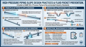
管線洩水坡度的核心目的是透過重力驅動,引導管內凝結水、廢液或固體雜質順利流向最低點的疏水閥(Steam Traps)或排放口,避免液體在管段中積存。在工業蒸氣管線或高壓多相流管線中,若洩水坡度不足或產生積水區域(Pockets),高速掠過的氣體會與積存的液體表面產生強烈摩擦,進而捲起液滴形成水段(Slug flow)。這些水段隨氣流高速衝擊下游的管件或閥門,便會引發具破壞性的「水錘效應(Water Hammer)」,其瞬間產生的動水壓力極易導致管系疲勞受損、支架斷裂甚至管壁爆裂。 The core purpose of the piping slope is to utilize gravity-driven forces to smoothly guide internal condensate, waste liquids, or solid impurities toward steam traps or drain points at the lowest elevation, preventing fluid accumulation within the pipe segments. In industrial steam lines or high-pressure multiphase pipelines, if the slope is insufficient or if pockets form, high-velocity sweeping gases will generate severe friction against the surface of the accumulated liquid. This scoops up liquid droplets to form slug flow. When these slugs impact downstream fittings or valves at high speeds, they trigger a highly destructive “Water Hammer” effect. The instantaneous dynamic water pressure generated can easily lead to piping fatigue damage, broken supports, or even pipe wall ruptures.
7.2 ASME 規範下之坡度標準與設計參數 / 7.2 Slope Standards and Design Parameters Under ASME Codes
洩水坡度的設計並非隨意為之,而需依據管系內的流體特性與流速進行精確計算。坡度的數學定義為垂直落差(H)與水平運行長度(L)的比值(S = H/L),常以百分比(%)或比例(如 1:100)表示。 The design of piping slopes is not arbitrary; it requires precise calculation based on the fluid characteristics and velocities within the system. The mathematical definition of slope is the ratio of vertical drop (H) to horizontal run length (L) (S = H/L), often expressed as a percentage (%) or a ratio (e.g., 1:100).
根據 ASME B31.1(動力管線)與 B31.3(製程管線)相關工程實務與規範指引:According to engineering practices and guidelines related to ASME B31.1 (Power Piping) and B31.3 (Process Piping):
- 高壓主蒸氣與冷凝管線:為確保冷凝水能迅速被推向下游疏水閥,管線必須順著蒸氣流動方向設置向下坡度。標準建議之最小坡度通常落在 1:240 至 1:480(約42% 至 0.21%,即每 10 英尺下降半英吋)之間。對於某些高壓或大流量之主蒸氣管線,為了徹底避免冷凝水被高速蒸氣反向捲起,部分設計標準甚至要求坡度不得小於 1:100(1%)。High-Pressure Main Steam and Condensate Lines: To ensure that condensate is rapidly swept toward downstream steam traps, the piping must be pitched downward in the direction of steam flow. The standard recommended minimum slope usually falls between 1:240 and 1:480 (approximately 0.42% to 0.21%, i.e., dropping half an inch every 10 feet). For certain high-pressure or high-flow main steam lines, to entirely prevent condensate from being swept backward by high-velocity steam, some design criteria mandate a slope of no less than 1:100 (1%).
- 濕氣與廢氣排放管線(Flare Headers):為避免液氣阻塞,此類管線通常要求約 1:500(20%)的坡度。 Wet Gas and Flare Headers: To prevent liquid holdup blockages, such lines typically require a slope of approximately 1:500 (0.20%).
7.3 熱膨脹、管線下垂與「坡度逆轉(Slope Reversal)」防範 / 7.3 Thermal Expansion, Pipe Sagging, and Prevention of “Slope Reversal”
靜態設計出的完美洩水坡度,在系統實際啟動後往往面臨嚴峻挑戰。高壓高溫管線在運行時會產生劇烈的材料熱膨脹(Thermal Expansion)。如果管線佈局或支撐點設計不當,熱膨脹所產生的向上位移量若超過了原始設計的微小下傾量,便會發生致命的「坡度逆轉(Slope Reversal)」現象。坡度逆轉會人為地在管系半空中創造出一個無法排水的「液體陷阱」,直接誘發水錘。 A perfectly designed static drainage slope frequently faces severe challenges once the system is actually started up. High-pressure and high-temperature piping experiences drastic material thermal expansion during operation. If the piping layout or support points are improperly designed, the upward displacement caused by thermal expansion might exceed the initially designed minute downward pitch, resulting in the fatal phenomenon known as “Slope Reversal”. Slope reversal artificially creates an undrainable “liquid trap” mid-air within the piping system, directly inducing water hammer.
此外,管系支撐跨距(Span length)的設計也直接影響坡度。若兩個支撐點之間的跨距過大,管材因自身與流體重量產生的撓曲下垂量(Sagging)一旦深於洩水坡度的高低差,同樣會形成積水窪地。因此,EPC 應力工程師必須仰賴 CAESAR II 等應力分析軟體,精確計算管系在各個操作工況(Operating conditions)下的垂直位移,並搭配適當的彈簧吊架(Spring Hangers)來吸收熱位移,從而保證在任何時刻管線都不會發生坡度逆轉。 In addition, the design of the support span length directly affects the slope. If the span between two support points is excessively large, the sagging caused by the pipe’s own weight and the fluid’s weight may exceed the elevation drop of the drainage slope, similarly forming a puddle. Thus, EPC stress engineers must rely on stress analysis software like CAESAR II to precisely calculate the vertical displacements of the piping across all operating conditions. Combined with appropriate Spring Hangers to absorb thermal displacements, this ensures that slope reversal never occurs at any time.
7.4 「以彎代銲」在洩水坡度佈局上的實務優勢 / 7.4 Practical Advantages of “Bend Instead of Weld” in Piping Slope Layouts
在實現微小且連續的洩水坡度時,傳統 1.5D 多銲道對銲結構顯露出其侷限性。為了湊出千分之幾的傾角,現場銲工在接合彎頭與直管時經常需要進行人為的「微調歪斜」點銲,這不僅容易導致銲口錯邊、增加內部應力,銲道根部的凸起(Weld Root Protrusion)更會成為阻礙薄層冷凝水順利排出的微型堤壩。When achieving minute and continuous drainage slopes, traditional 1.5D multi-pass welded structures expose their limitations. To cobble together an inclination of just a few parts per thousand, field welders often have to perform artificial “skewed tack welds” when joining elbows to straight pipes. This not only easily leads to weld misalignment and increased internal stresses, but the weld root protrusions also act as micro-dams that hinder the smooth drainage of thin condensate films.
相對地,導入 CNC 冷作彎管技術能為洩水坡度設計帶來顛覆性的優勢。透過電腦數控機台的精密計算,可直接在彎管加工時將所需的洩水仰角或俯角整合於 3D 空間幾何中,做到真正的一體成型。冷彎管平滑無接縫的內壁徹底消除了滯水死角,讓微小的冷凝水滴與雜質能順暢無阻地滑落至集水區,完美契合了 ASME 對於管系排液及防止水錘效應的嚴苛要求。Conversely, introducing CNC cold bending technology brings disruptive advantages to drainage slope design. Through precise calculations by the CNC machine, the required upward or downward pitch for drainage can be directly integrated into the 3D spatial geometry during the bending process, achieving true one-piece forming. The smooth, seamless inner wall of cold bends thoroughly eliminates dead zones where water can stagnate, allowing tiny condensate droplets and impurities to glide unimpeded into collection areas, perfectly aligning with ASME’s rigorous requirements for piping drainage and water hammer prevention.
八、結論 / 8. Conclusion
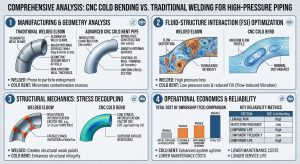
本研究透過整合流體動力學與固體力學理論,並依據最新工業法規與 CFD 數值模擬文獻,針對高壓油壓管線落實「能彎不銲」方針進行了窮盡性的剖析。對比傳統 1.0D 套銲、1.5D 對銲彎頭與現代 3D/5D CNC 冷作彎管的性能特徵,得出以下核心結論:By integrating theories of fluid dynamics and solid mechanics, and referencing the latest industrial codes and CFD numerical simulation literature, this study has conducted an exhaustive analysis on implementing the “Bend Instead of Weld” approach for high-pressure hydraulic piping. Comparing the performance characteristics of traditional 1.0D socket-welded, 1.5D butt-welded elbows, and modern 3D/5D CNC cold bends, the following core conclusions are drawn:
- 製造工法的現代化與精準控制 / Modernization and Precise Control of Manufacturing Methods:現代 CNC 旋繞拉彎(RDB)技術搭配伺服回彈補償與精密芯棒系統,已能完全克服壁厚減薄與橢圓化的挑戰,精準產出符合 ASME B31.3 與1 嚴苛幾何公差的高品質一體成型彎管,打破了以往大管徑與薄壁管僅能依賴銲接的迷思。Modern CNC Rotary Draw Bending (RDB) technology, combined with servo springback compensation and precision mandrel systems, can now completely overcome challenges of wall thinning and ovalization. It precisely yields high-quality, integrally formed bends that meet the rigorous geometric tolerances of ASME B31.3 and B31.1, shattering the old myth that large-diameter and thin-walled pipes can only rely on welding.
- 流體動力效率的極致提升 / Ultimate Enhancement of Fluid Dynamic Efficiency:透過將彎曲半徑由0D/1.5D 放寬至 3D 或 5D,有效降低了狄恩數(De),抑制了強烈二次流與流動分離的發生。依據伊藤公式與計算流體力學分析,其損失係數 K 呈現指數級下降。同時,連續平滑的無銲道內壁徹底消除了觸發空穴微射流與局部沖蝕的幾何缺陷,大幅延長了管件在嚴苛多相流下的壽命。By relaxing the bending radius from 1.0D/1.5D to 3D or 5D, the Dean Number (De) is effectively lowered, suppressing the occurrence of intense secondary flows and flow separation. According to Ito’s formula and CFD analysis, the loss coefficient K decreases exponentially. Concurrently, the continuous and smooth weld-free inner wall completely eliminates the geometric flaws that trigger cavitation micro-jets and localized erosion, drastically extending component life under harsh multiphase flows.
- 結構可靠度與疲勞完整性的飛躍 / Leaps in Structural Reliability and Fatigue Integrity:捨棄銲接等同於消除了管系中最脆弱的熱影響區(HAZ)與套銲間隙(Crevice),杜絕了微裂紋的溫床。在即將全面實施的 ASME B31J-2026 規範下,3D/5D 冷彎管展現出極低的應力強化係數(SIF ≈0),極大地提升了管網吸收振動(FIV、AIV)與熱膨脹的柔性餘裕。Abandoning welding is tantamount to eliminating the most vulnerable Heat-Affected Zone (HAZ) and socket weld crevices in piping systems, cutting off the breeding ground for microcracks. Under the soon-to-be-enforced ASME B31J-2026 code, 3D/5D cold bends exhibit exceptionally low Stress Intensification Factors (SIF ≈1.0), vastly increasing the piping network’s flexibility margin to absorb vibrations (FIV, AIV) and thermal expansion.
- 利害關係人痛點之解決與三合一工法之利基 / Resolution of Stakeholder Pain Points and the Niche of the Three-in-One Method:從業主的 LCC 考量、EPC 的空間佈置解鎖、到廠務端對於小管徑(SBP)振動疲勞的防範,「能彎不銲」提供了本質安全的物理屏障。特別是導入潁璋工程提倡的「3D/5D CNC 冷作彎管 + IH-PBHT 感應熱處理 + QR Code 數位履歷」三合一工法,完美對接了 ASME 嚴苛標準,將傳統黑箱的配管工程昇華為可追溯的高精度製造。From owners’ LCC considerations and the unlocking of EPC spatial layouts, to facility management’s prevention of Small Bore Piping (SBP) vibration fatigue, “Bend Instead of Weld” provides an inherently safe physical barrier. In particular, adopting the “3D/5D CNC Cold Bend + IH-PBHT Induction Heating + QR Code Digital Traceability” Three-in-One Method advocated by Ying-Zhang Engineering perfectly interfaces with stringent ASME standards, elevating traditional black-box piping engineering into traceable, high-precision manufacturing.
- 洩水坡度佈局優勢 / Advantages in Piping Slope Layout:在預防冷凝水積存與水錘效應的洩水坡度設計中,冷作彎管平滑無銲道的內壁特性,搭配可於 3D 幾何中直接成型傾角的彈性,完美解決了傳統銲道根部易阻礙微量積水及引發「坡度逆轉」的實務挑戰。In piping slope designs aimed at preventing condensate holdup and water hammer effects, the smooth, weld-free inner wall of cold bends—coupled with the flexibility to form inclination angles directly in 3D geometry—perfectly resolves the practical challenges of traditional weld roots obstructing minor water accumulation and triggering “slope reversal.”
綜觀全局,以 CNC 冷作彎管全面取代傳統銲接彎頭,不僅是單一製造工法的改變,更是高壓流體管線工程中流固耦合最佳化、應力解耦與營運經濟性的完美結合。此方針順應了全球工業邁向高壓化、精密化與極致可靠度的必然發展趨勢,極具學術與實務推廣價值。Taking a comprehensive view, fully replacing traditional welded elbows with CNC cold bends is not merely a change in a single manufacturing method; it is the perfect fusion of fluid-structure interaction optimization, stress decoupling, and operational economics in high-pressure fluid piping engineering. This approach aligns with the inevitable developmental trend of global industry toward higher pressures, greater precision, and ultimate reliability, possessing immense value for both academic research and practical promotion.
參考文獻 / References
- Pipe Fittings Supplier UAE | Carbon Steel & SS Fittings, https://naftaar.com/pipe-fittings-supplier/
- Pipe Fittings Selection Guide Piping System, https://txdpipe.com/blog-detail/pipe-fittings-selection-guide-piping-system
- 傳統配管與冷作彎管工法於高能管線生命週期完整性之法規與實務, https://yz-pipe-bending.com.tw/%E8%81%9A%E7%84%A6%E7%94%9F%E5%91%BD%E9%80%B1%E6%9C%9F%E5%AE%89%E5%85%A8%EF%BC%9A%E5%82%B3%E7%B5%B1%E9%85%8D%E7%AE%A1%E8%88%87%E5%86%B7%E4%BD%9C%E5%BD%8E%E7%AE%A1%E5%B7%A5%E6%B3%95%E6%96%BC%E9%AB%98/
- Piping Interview Questions and Answers (2026) – Aienginear, https://aienginear.com/piping-interview-questions/
- nevada nv a-20 industrial piping contractor – Docsity, https://www.docsity.com/en/docs/nevada-nv-a-20-industrial-piping-contractor-examination-complete-questions-and-detailed-s-8/21256924/
- Piping System Rerating and Inspection Guidelines | PDF – Scribd, https://www.scribd.com/document/619495947/quizlet-1