
摘要 / Abstract
在全球能源轉型的宏觀背景下,電網系統對再生能源的依賴度急遽上升,其間歇性特質迫使傳統燃氣複循環發電廠(Combined Cycle Power Plant, CCPP)自過往的基載運轉模式,全面轉型為肩負深度調峰(Cycling)重任的關鍵節點。此一運轉典範的轉移,導致廠內主蒸汽(Main Steam)與高溫再熱蒸汽(Hot Reheat Steam)等高能管線(High Energy Piping, HEP)長期暴露於極端熱力學條件(高於 540°C 至 600°C)下,並承受劇烈的低週期熱疲勞(Low-Cycle Thermal Fatigue)與高溫潛變交互破壞(Creep-Fatigue Interaction)。與此同時,美國機械工程師學會(ASME)於最新發布之 B31.1(動力管線)與 B31.3(製程管線)規範中,正式宣告沿用逾半世紀的 Appendix D 經驗公式走入歷史,並全面強制導入基於現代高精度有限元素分析(FEA)的 ASME B31J 規範,作為決定應力強度因子(SIF)與柔性因子(k-Factor)的唯一法定運算核心。In the macro context of the global energy transition, the reliance of grid systems on renewable energy has increased sharply. The inherent intermittency of renewables has forced traditional Combined Cycle Power Plants (CCPP) to transition from their historical base-load operation mode to becoming key nodes responsible for deep cycling. This paradigm shift in operation causes in-plant High Energy Piping (HEP), such as Main Steam and Hot Reheat Steam lines, to be exposed to extreme thermodynamic conditions (above 540°C to 600°C) for prolonged periods, subjecting them to severe Low-Cycle Thermal Fatigue and Creep-Fatigue Interaction. Meanwhile, in the latest editions of the B31.1 (Power Piping) and B31.3 (Process Piping) codes, the American Society of Mechanical Engineers (ASME) has officially announced the retirement of the half-century-old Appendix D empirical formulas. The codes now mandate the implementation of the ASME B31J standard, which is based on modern high-precision Finite Element Analysis (FEA), as the sole legal calculation core for determining Stress Intensification Factors (SIF) and Flexibility Factors (k-Factors).
本研究深度剖析 ASME B31J 規範全面強制化對既有 CCPP 高溫高壓管系所引發之「應力分析衝擊(Stress Analysis Shock)」。研究首先闡明 B31J 如何透過三維空間矩陣將平面內、平面外與扭轉 SIF 徹底解耦,並結合 B31.1 2024 年版強制導入之厚壁管 Lamé 方程式,揭示舊規範在持續應力與熱膨脹應力評估上的非保守盲點。其次,本研究透過 CAESAR II 應力分析平台,結合 Larson-Miller 參數(LMP)潛變預測模型,對 P91/P92 高階耐熱鋼之微觀劣化行為進行數值與壽命量化分析。針對評估後之應力超標與潛變熱點,本報告提出以「能彎不銲」之 3D/5D 無縫冷作彎管取代傳統 1.5D 銲接彎頭的物理改造工法。最終,導入解析層級程序法(AHP)與多準則決策分析(MCDA),並深入探討廠務管理、EPC 設計、協力廠商因應策略及「三合一工法」之實務合規性,為現代 CCPP 廠提供具備高度工程可行性與經濟效益之管系再驗證與優化策略。This study provides an in-depth analysis of the “Stress Analysis Shock” triggered by the mandatory implementation of the ASME B31J code on the existing high-temperature and high-pressure piping systems in CCPP. The research first elucidates how B31J thoroughly decouples the in-plane, out-of-plane, and torsional SIFs through a 3D spatial matrix. Combined with the mandatory introduction of the Lamé equations for thick-walled pipes in the 2024 edition of B31.1, it reveals the non-conservative blind spots of the legacy code in evaluating sustained stress and thermal expansion stress. Secondly, through the CAESAR II stress analysis platform combined with the Larson-Miller Parameter (LMP) creep prediction model, this study conducts numerical and quantitative life span analyses on the microstructural degradation behavior of P91/P92 advanced heat-resistant steels. Addressing the stress-exceeding and creep hotspots identified post-evaluation, this report proposes a physical modification method that replaces traditional 1.5D welded elbows with 3D/5D seamless cold-formed bends, adhering to the “bend-instead-of-weld” strategy. Ultimately, by introducing the Analytical Hierarchy Process (AHP) and Multi-Criteria Decision Analysis (MCDA), and deeply exploring plant management, EPC design, subcontractor coping strategies, and the practical compliance of the “Three-in-One Method,” this study provides modern CCPP facilities with highly feasible and economically beneficial re-evaluation and optimization strategies for piping systems.
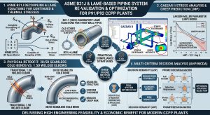
一、產業背景與法規演進之系統性衝擊 / 1. Systemic Impact of Industrial Background and Code Evolution
1.1 全球能源轉型下 CCPP 機組之嚴苛運轉挑戰 / 1.1 Severe Operational Challenges of CCPP Units under Global Energy Transition
隨著淨零碳排(Net Zero)成為全球共識,風能與太陽能等再生能源在總體發電配比中的滲透率呈現指數型增長1。然而,再生能源固有的間歇性與不可預測性,對電網的頻率穩定度與電壓控制構成了極大挑戰。在此背景下,燃氣複循環發電廠(CCPP)因具備極高的負載追隨(Load Following)能力與快速啟動特性,逐漸從傳統的基載(Base-load)供電角色,轉型為吸收電網波動的調峰(Peaking)主力1。 As Net Zero becomes a global consensus, the penetration rate of renewable energy sources such as wind and solar power in the overall power generation mix is showing exponential growth1. However, the inherent intermittency and unpredictability of renewables pose a significant challenge to the frequency stability and voltage control of the power grid. Against this backdrop, Combined Cycle Power Plants (CCPP), due to their exceptional load-following capabilities and fast-start characteristics, are gradually transitioning from their traditional base-load power supply roles to becoming the main force in peaking operation to absorb grid fluctuations1.
以台灣電力系統為例,興達電廠、大潭電廠、通霄電廠與大林電廠等大型燃氣機組,為因應半導體產業擴廠(如 AI 科技發展)及區域供電穩定,正經歷大規模的更新改建計畫,引進總裝置容量龐大的高效率燃氣機組(如通霄電廠 M501JAC 機組)3。現代化超超臨界(Ultra-Supercritical, USC)與先進 CCPP 機組(如 Siemens HL 級氣渦輪機,點火溫度可達 1704°C),其熱回收廢熱鍋爐(HRSG)所產生的主蒸汽與高溫再熱蒸汽,運轉溫度通常介於 540°C 至 620°C 之間,壓力高達數百巴(bar)2。 Taking Taiwan’s power system as an example, large-scale gas-fired units such as the Hsinta, Datan, Tunghsiao, and Talin Power Plants are undergoing massive renewal and expansion projects to accommodate the expansion of the semiconductor industry (e.g., AI technology development) and to ensure regional power supply stability. These projects introduce high-efficiency gas-fired units with a massive total installed capacity (such as the M501JAC units at Tunghsiao Power Plant)3. For modernized Ultra-Supercritical (USC) and advanced CCPP units (e.g., the Siemens HL-class gas turbine with a firing temperature up to 1704°C), the main steam and hot reheat steam generated by their Heat Recovery Steam Generators (HRSG) typically operate at temperatures between 540°C and 620°C and pressures reaching hundreds of bars2.
在頻繁啟停與負載升降的交變熱力負荷下,高能管線系統內部產生了極大的溫度梯度,進而引發嚴重的低週期熱疲勞2。當此類熱應力循環疊加超高溫環境下的金屬潛變(Creep)效應時,管系材質將發生不可逆的微觀組織劣化。尤其在應力集中的管件交會處與傳統電銲接頭(Welded Joints)之熱影響區(HAZ),極易誘發具毀滅性的第四型潛變破裂(Type IV Creep Cracking)2。此一現象凸顯了對既有高能管線進行精確應力評估與生命週期管理的迫切性。 Under the alternating thermodynamic loads caused by frequent startups, shutdowns, and load ramping, immense temperature gradients are generated within the high-energy piping systems, subsequently triggering severe low-cycle thermal fatigue2. When such thermal stress cycles are superimposed with metal creep effects in ultra-high-temperature environments, the piping materials undergo irreversible microstructural degradation. Particularly at stress-concentrated piping intersections and the Heat-Affected Zones (HAZ) of traditional welded joints, this is highly prone to inducing devastating Type IV Creep Cracking2. This phenomenon highlights the urgent need for precise stress evaluation and life cycle management of existing high-energy piping.
1.2 ASME B31 規範體系之歷史侷限與安全裕度差異 / 1.2 Historical Limitations and Safety Margin Differences of the ASME B31 Code System
為了確保高壓流體輸送系統之結構完整性,美國機械工程師學會(ASME)制定了 B31 壓力管線規範體系,其中以 ASME B31.1(動力管線)與 B31.3(製程管線)為工程界最廣泛依循之兩大核心準則2。 To ensure the structural integrity of high-pressure fluid transportation systems, the American Society of Mechanical Engineers (ASME) developed the B31 Pressure Piping Code system, wherein ASME B31.1 (Power Piping) and B31.3 (Process Piping) act as the two core standards most widely followed by the engineering industry2.
ASME B31.1 專注於發電站內輸送高壓高溫蒸汽與水之管系,其管轄界線涵蓋與動力鍋爐直接相連之鍋爐外部管線(Boiler External Piping, BEP),自鍋爐本體延伸至第一個授權隔離閥,具備極高的法規強制性2。由於動力管線一旦發生破裂將引發災難性後果,B31.1 歷史上採用極為保守的設計安全係數(Safety Margin)。其容許應力(Allowable Stress, S)上限對抗金屬最小抗拉強度(ST)的安全係數設定為 4.0,後雖配合材料科學進展微調至 3.5,但仍確保系統具備對抗長期整體結構失效的極致可靠性2。相對而言,ASME B31.3 多應用於煉油與石化廠,其安全係數通常設定為 3.0,並將容許應力上限封頂於降伏強度的三分之二,允許使用較薄的管壁。 ASME B31.1 focuses on the piping systems transporting high-pressure, high-temperature steam and water within power stations. Its jurisdictional boundary covers the Boiler External Piping (BEP) directly connected to the power boiler, extending from the boiler proper to the first authorized isolation valve, possessing a highly mandatory regulatory nature2. Because the rupture of power piping would trigger catastrophic consequences, B31.1 has historically adopted extremely conservative design safety margins. Its safety factor for the upper limit of allowable stress (S) against the material’s minimum tensile strength (ST) was set at 4.0. Although later slightly adjusted to 3.5 in alignment with advancements in materials science, it still ensures the system has ultimate reliability against long-term overall structural failure2. Comparatively, ASME B31.3 is mostly applied in refineries and petrochemical plants, with its safety factor typically set at 3.0 and the allowable stress limit capped at two-thirds of the yield strength, permitting the use of thinner pipe walls.
| 規範比較參數 / Code Comparison Parameters | ASME B31.1 (動力管線 / Power Piping) | ASME B31.3 (製程管線 / Process Piping) |
| 主要適用場域 / Main Application Area | 發電廠主蒸汽、高溫再熱蒸汽、給水系統 / Power plant main steam, hot reheat steam, feedwater systems | 煉油廠、化學工廠、一般流體製程 / Refineries, chemical plants, general fluid processes |
| 基本安全係數 / Basic Safety Factor | 3.5 至 4.0 (對抗極限抗拉強度 Su) / 3.5 to 4.0 (Against Su ultimate tensile strength) | 3.0 (對抗極限抗拉強度Su ) / 3.0 (Against ultimate tensile strength Su) |
| 降伏強度限制 / Yield Strength Limit | ≦ 62.5%的降伏強度 (Sy) / ≦ 62.5% of yield strength (Sy) | ≦ 66.7% 的降伏強度 (Sy) / ≦ 66.7% of yield strength (Sy)2 |
| 管壁厚度影響 / Wall Thickness Impact | 傾向強制採用極端厚壁 (如 Sch 160 / XXS) / Tends to mandate extreme thick walls (e.g., Sch 160 / XXS) | 允許相對較薄管壁 (如 Sch 40 / Sch 80) / Permits relatively thinner pipe walls (e.g., Sch 40 / Sch 80) |
| 系統剛性特徵 / System Stiffness Characteristics | 高厚徑比導致系統整體剛度 (Stiffness) 劇增 / High D/T ratio leads to a sharp increase in overall system stiffness | 柔性較佳,熱膨脹應力較易消散 / Better flexibility, easier dissipation of thermal expansion stress |
在相同的高溫高壓設計條件下,B31.1 強制要求較厚的管壁,而此一厚壁特徵會導致系統剛度矩陣中的勁度急遽上升,對熱膨脹應力的消散產生連鎖負面影響。Under identical high-temperature and high-pressure design conditions, B31.1 mandates thicker pipe walls. This thick-walled characteristic leads to a sharp increase in stiffness within the system’s stiffness matrix, generating a cascading negative impact on the dissipation of thermal expansion stresses.
1.3 Markl 經驗公式之崩解與 B31J 的歷史必然性 / 1.3 The Collapse of Markl’s Empirical Formulas and the Historical Inevitability of B31J
長達七十餘年,ASME B31.1 與 B31.3 評估管線幾何不連續處(如三通、彎頭、異徑管)應力集中的依據,皆仰賴 1950 年代 A.R.C. Markl 所建立的 Appendix D 經驗公式2。然而,Markl 的實驗存在極大的先天侷限:其數據庫幾乎完全建立在 4 吋標準壁厚(Standard Weight)、厚徑比極小的碳鋼無縫管件之全反轉彎曲疲勞測試上2。 For over seventy years, both ASME B31.1 and B31.3 relied on the Appendix D empirical formulas established by A.R.C. Markl in the 1950s as the basis for evaluating stress concentrations at piping geometric discontinuities (such as tees, elbows, and reducers)2. However, Markl’s experiments possessed a massive inherent limitation: his database was almost entirely built upon fully reversed bending fatigue tests of 4-inch standard weight seamless carbon steel pipe components with an extremely small D/T ratio2.
現代高精度有限元素分析(FEA)與 Paulin Research Group (PRG) 所收集的海量實體驗證數據指出,Markl 公式中隱含的疲勞曲線斜率係數為 5.0,而現代疲勞試驗與其他疲勞規範(如 ASME 鍋爐及壓力容器規範第 III 卷)皆強烈支持銲接管件的疲勞曲線斜率應接近 3.0。此一斜率差異導致舊規範在評估低週期疲勞(這正是現代 CCPP 廠面臨的典型負載)時,會給出不合理且過低的應力強度因子(SIF),而在高週期疲勞區間,又會危險地高估管件的疲勞壽命。Modern high-precision Finite Element Analysis (FEA) and the massive volume of physical validation data collected by the Paulin Research Group (PRG) indicate that the fatigue curve slope coefficient implicit in Markl’s formulas is 5.0, whereas modern fatigue tests and other fatigue codes (such as ASME Boiler and Pressure Vessel Code Section III) strongly support that the fatigue curve slope for welded components should be close to 3.0. This slope discrepancy results in the legacy codes producing unreasonably low Stress Intensification Factors (SIF) when evaluating low-cycle fatigue (which is exactly the typical load faced by modern CCPP plants), while dangerously overestimating the fatigue life of components in the high-cycle fatigue regime.
為彌補此一可能導致災難性後果的法規漏洞,ASME 發布了 B31J 規範(金屬管線組件應力強度因子與柔性因子判定標準)。在 2024 與 2026 年版的 ASME B31.1 及 2020 年版之後的 B31.3 中,已正式廢除長久以來的 Appendix D,強制將 B31J 作為 SIF 與柔性因子計算的唯一合法基準2。此一典範轉移宣告了經驗公式時代的終結,並引爆了全球管線工程界的應力再驗證浪潮。 To mend this regulatory loophole that could lead to catastrophic consequences, ASME published the B31J code (Standard for Determining Stress Intensification Factors and Flexibility Factors for Metallic Piping Components). In the 2024 and 2026 editions of ASME B31.1 and the post-2020 editions of B31.3, the longstanding Appendix D has been officially abolished, mandating B31J as the sole legal baseline for calculating SIFs and flexibility factors2. This paradigm shift proclaims the end of the empirical formula era and has ignited a wave of stress re-evaluations across the global piping engineering industry.
二、ASME B31J 力學矩陣解耦與核心演算法解析 / 2. Decoupling of the Mechanical Matrix and Core Algorithm Analysis of ASME B31J
2.1 三維空間 SIF 之向量解耦機制 / 2.1 Vector Decoupling Mechanism of SIF in 3D Space
傳統 Appendix D 的數學模型過於簡化。針對三通(Tees)與分支管連接,舊規範僅計算單一的特徵幾何參數h = 4.4*(T/r),進而推導出單一的純量 SIF 值 i = 0.9/h2/3,並將此單一最大值同時粗暴地套用於平面內(In-Plane)與平面外(Out-of-Plane)的彎矩計算上。更為致命的是,舊規範將扭轉 SIF(Torsional SIF, it)一律預設為 1.0,完全忽視了交會管件在承受扭轉剪應力時的應力集中與變形放大效應。 The mathematical model of the traditional Appendix D was overly simplified. For tees and branch connections, the legacy code merely calculated a single characteristic geometric parameter h = 4.4*(T/r), subsequently deriving a single scalar SIF value i = 0.9/h2/3. This single maximum value was then crudely applied simultaneously to both in-plane and out-of-plane bending moment calculations. Even more critically, the legacy code universally defaulted the Torsional SIF (it) to 1.0, completely ignoring the stress concentration and deformation amplification effects when intersecting components are subjected to torsional shear stress.
ASME B31J-2023 全面顛覆了此一保守且失真的作法,藉由嚴謹的 FEA 解析與實驗迴歸,將單一 SIF 徹底解耦為三組獨立的空間向量特徵值6:ASME B31J-2023 thoroughly overturned this conservative and distorted approach. Through rigorous FEA analysis and experimental regression, it thoroughly decoupled the single SIF into three independent spatial vector characteristic values6:
- 平面內應力強度因子 (ii):針對彎矩作用於管件主平面內所引發的應力集中。In-Plane SIF (ii): Addresses the stress concentration induced when the bending moment acts within the component’s primary plane.
- 平面外應力強度因子 (io):針對迫使管件偏離主軸平面變形之彎矩放大效應。Out-of-Plane SIF (io): Addresses the bending moment amplification effect that forces the component to deform away from its principal axis plane.
- 扭轉應力強度因子 (it):精確量化管件在承受沿中心軸旋轉扭矩時的剪切變形集中度。 Torsional SIF (it): Accurately quantifies the shear deformation concentration when the component is subjected to twisting moments along its central axis.
在 B31J 表 1-1(Table 1-1)的架構下,針對未補強之銲接三通(Unreinforced Fabricated Tees)或斜交分支管(Lateral Branch Connections),其 ii、io 與 it 皆具備獨立的幾何修正公式,且將主管與分支管之外徑比(d/D)及厚徑比( D/t)作為核心變數。這使得應力工程師能精確捕捉管件在三維空間中因非對稱負載所導致的局部降伏與疲勞萌生點。 Under the framework of B31J Table 1-1, for unreinforced fabricated tees or lateral branch connections, their ii, io, and it all possess independent geometric correction formulas, utilizing the branch-to-run outer diameter ratio (d/D) and the diameter-to-thickness ratio (D/t) as core variables. This allows stress engineers to accurately capture local yielding and fatigue initiation points caused by asymmetrical loads on piping components in 3D space.
2.2 柔性因子 (k-Factor) 之擴展與系統剛度重組 / 2.2 Expansion of k-Factors and Recombination of System Stiffness
在管線系統的熱膨脹分析中,柔性因子(Flexibility Factor, k)定義了管件在單位彎矩下的角位移相對於等長直管的倍率。傳統規範僅承認彎管(Elbows)與彎管接頭具備k > 1 的柔性,而將所有三通及管嘴視為絕對剛性( k = 1)。In the thermal expansion analysis of piping systems, the Flexibility Factor (k) defines the angular displacement ratio of a component under a unit bending moment relative to a straight pipe of equal length. Traditional codes only acknowledged that elbows and pipe bends possessed flexibility with k > 1, while treating all tees and nozzles as absolutely rigid (k = 1).
ASME B31J 透過大量非線性 FEA 證明,當薄壁大管徑之主管承受分支管傳遞之彎矩時,三通交會點實際上存在顯著的局部旋轉變形能力。B31J 為三通賦予了三個獨立的柔性因子,這直接改變了整體管線系統的剛度矩陣(Stiffness Matrix)。當系統剛度被重新分配時,熱膨脹變形將會沿著阻力最小的路徑重新釋放,導致管線終端連接設備(如氣渦輪機管口、泵浦法蘭)的負載(Nozzle Loads)計算結果發生巨幅變動。若能善用此一真實柔性,工程師可有效減少不必要的彈簧吊架或膨脹迴圈設置;反之,若忽略之,將導致設備管口應力超標而失效。 ASME B31J has proven through extensive non-linear FEA that when a thin-walled, large-diameter run pipe is subjected to a bending moment transmitted from a branch pipe, the tee intersection actually exhibits a significant capacity for local rotational deformation. B31J assigns three independent flexibility factors to tees, which directly alters the stiffness matrix of the entire piping system. As the system stiffness is redistributed, thermal expansion deformations will release along the path of least resistance, leading to massive fluctuations in the calculated loads on terminal connected equipment (such as gas turbine nozzles or pump flanges). By properly leveraging this true flexibility, engineers can effectively reduce the unnecessary installation of spring hangers or expansion loops; conversely, ignoring it will result in equipment nozzle stress overload and failure.
2.3 厚壁管 Lamé 方程式導入與持續應力指數 (SSI) 修正 / 2.3 Introduction of Lamé Equations for Thick-Walled Pipes and Sustained Stress Index (SSI) Modification
除了 B31J 的 SIF 解耦外,ASME B31.1 在 2024 年版針對持續應力(Sustained Stress)之縱向壓力計算實施了決定性的改革。長久以來,工程界廣泛套用薄壁圓筒理論的近似公式 Slp=PD/4t 來計算縱向壓力應力。然而,CCPP 主蒸汽管線為承受超高壓力,常採用壁厚極厚的材料(如外徑 300 mm 以上,厚度達 40 mm 以上之高合金管),其厚徑比已不適用於薄壁假設,繼續使用近似公式將產生危險的非保守誤差4。 In addition to B31J’s SIF decoupling, the 2024 edition of ASME B31.1 implemented a decisive reform regarding the calculation of longitudinal pressure stress for sustained stress. For a long time, the engineering industry widely applied the approximate formula Slp=PD/4t derived from thin-walled cylinder theory to calculate longitudinal pressure stress. However, to withstand ultra-high pressure, CCPP main steam piping often employs extremely thick-walled materials (e.g., high-alloy pipes with an outer diameter over 300 mm and a thickness exceeding 40 mm). Their D/T ratio no longer suits the thin-wall assumption, and continuing to use the approximate formula will yield dangerous non-conservative errors4.
為消除此一隱患,B31.1 強制要求工程師回歸基於拉梅厚壁圓筒理論(Lamé equations)的精確公式(Equation 15)4: To eliminate this hidden danger, B31.1 mandates that engineers revert to the exact formula (Equation 15) based on the Lamé equations for thick-walled cylinders4:
Slp=P⋅d2/(D2-d2)
在該方程式中,P 為內部設計壓力;D 為名目外徑;而最關鍵的參數 d,必須是扣除製造厚度公差(如無縫管常見的 -12.5%)、腐蝕裕度(Corrosion Allowance)、沖蝕裕度及螺紋切削裕度後,管系所面臨之最惡劣淨有效內徑。In this equation, P is the internal design pressure; D is the nominal outside diameter; and the most critical parameter d must be the worst-case net effective inside diameter faced by the piping system after deducting manufacturing thickness tolerances (e.g., the typical -12.5% for seamless pipes), corrosion allowance, erosion allowance, and thread cutting allowance.
此外,針對因內壓與自重引起的持續負載,B31.1 規定必須套用持續應力指數(Sustained Stress Index, SSI),定義為I=0.75×B31J i-Factor,且在任何情況下其值不得小於 1.0(即不能低於直管的應力狀態)5。此一規定(0.75i)源自於 Markl 時代對一次應力(Primary Stress)不會引發疲勞但會導致塑性崩塌的認知。厚壁 Lamé 方程式的導入與 0.75i 乘數的疊加,正是導致既有高溫高壓動力管線在 B31J 強制導入後,頻繁出現持續應力超標警告的核心原因。 Furthermore, for sustained loads caused by internal pressure and dead weight, B31.1 dictates the mandatory application of the Sustained Stress Index (SSI), defined as I=0.75×B31J i-Factor , and under no circumstances shall its value be less than 1.0 (i.e., it cannot be lower than the stress state of a straight pipe)5. This rule (0.75i) stems from the Markl era’s understanding that primary stress does not induce fatigue but leads to plastic collapse. The introduction of the thick-walled Lamé equations superposed with the 0.75i multiplier is the core reason why existing high-temperature and high-pressure power piping frequently displays sustained stress overload warnings post mandatory B31J implementation.
| 應力評估核心元素 / Core Elements of Stress Evaluation | ASME B31.1 舊規範架構 / Legacy ASME B31.1 Framework | 2024/2026 年版 B31.1 & B31J 新架構 / New 2024/2026 B31.1 & B31J Framework | 工程實務影響 / Engineering Practical Impact |
| 縱向壓力應力 (Slp) / Longitudinal Pressure Stress (Slp) | 近似公式 (PD/4t) / Approximate formula (PD/4t) | 厚壁 Lamé 淨內徑公式 (P⋅d2/(D2-d2)) / Thick-wall Lamé net inside diameter formula (P⋅d2/(D2-d2)) | 厚壁管線壓力應力值大幅上升,降低持續應力之安全裕度。Pressure stress values for thick-walled pipes rise sharply, reducing the safety margin of sustained stress. |
| 持續應力指數 (SSI) / Sustained Stress Index (SSI) | 常套用i =1.0 或舊版 Appendix D / Usually applied i =1.0 or legacy Appendix D | 強制使用I = max(0.75×B31J,1.0)/ Mandated use of I = max(0.75×B31J,1.0) | 三通與異徑管處自重彎矩被放大,暴露出隱藏的一次應力熱點。Deadweight bending moments at tees and reducers are amplified, exposing hidden primary stress hotspots. |
| 熱位移應力範圍 (SE) / Thermal Displacement Stress Range (SE) | 單一最大 SIF (純量) / Single maximum SIF (Scalar) | 全向三維解耦 SIF (ii,io,it) / (Omnidirectional 3D decoupled SIF (ii,io,it) | 精確捕捉扭轉與平面外疲勞,低週期熱疲勞壽命預測更為精確。Accurately captures torsional and out-of-plane fatigue; low-cycle thermal fatigue life prediction becomes more precise. |
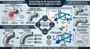
三、基於 CAESAR II 之應力再驗證與數值模擬架構 / 3. CAESAR II-Based Stress Re-evaluation and Numerical Simulation Architecture
面對 B31J 帶來的法規巨變,既有 CCPP 廠必須依賴如 CAESAR II 等先進管線應力分析軟體進行全面的系統再驗證。軟體模型必須精準還原物理邊界條件、流體力學效應與支撐非線性行為。Facing the monumental regulatory changes brought by B31J, existing CCPP facilities must rely on advanced piping stress analysis software, such as CAESAR II, to conduct a comprehensive system re-evaluation. The software model must precisely replicate physical boundary conditions, fluid dynamic effects, and support non-linear behaviors.
3.1 載荷工況 (Load Cases) 定義與熱力學疊加 / 3.1 Definition of Load Cases and Thermodynamic Superposition
管線系統在真實運轉中並非承受單一負載,而是多重物理量的耦合。在 CAESAR II 建立 B31J 分析模型時,需嚴格定義以下標準載荷工況:In real-world operations, piping systems do not endure a single load but rather a coupling of multiple physical variables. When building a B31J analysis model in CAESAR II, the following standard load cases must be strictly defined:
- 持續負載工況:組合代碼通常為 W+P1(自重 + 內壓)。此工況屬於非自我緩解(Non-self-limiting)之一次應力,若金屬發生降伏,變形將持續擴大直至管系崩塌。分析中必須鎖定彈簧吊架的冷態預力(Pre-loads),並透過1 公式 (15) 檢核應力是否低於高溫容許應力 Sh。Sustained Case (SUS): The combination code is typically W+P1 (Weight + Internal Pressure). This case represents non-self-limiting primary stress; if the metal yields, deformation will continue to expand until system collapse. In the analysis, the cold pre-loads of spring hangers must be locked, and B31.1 Equation (15) is used to verify if the stress is below the hot allowable stress Sh .
- 操作負載工況:組合代碼為W+P1+T1(自重 + 內壓 + 熱膨脹)。此工況模擬電廠實際高溫滿載狀態。在此工況下,分析師需檢查彈簧吊架是否發生「支撐脫離(Lift-off)」、非線性導向支架(Guide Gaps)是否閉合,以及管線在鋼構支撐上的摩擦力(一般鋼對鋼設定摩擦係數 μ = 0.3)是否引發額外的拘束應力。Operating Case (OPE): The combination code is W+P1+T1 (Weight + Internal Pressure + Thermal Expansion). This case simulates the actual high-temperature full-load state of the power plant. Under this case, the analyst needs to check if spring hangers experience “lift-off,” if non-linear guide gaps close, and if the friction force of the pipe on the steel supports (generally setting a friction coefficient μ = 0.3 for steel-on-steel) induces additional restraint stress.
- 膨脹位移工況:此為評估熱疲勞的關鍵工況。由於熱膨脹屬於位移驅動之次要應力(Secondary Stress),具備變形後自我緩解特性,規範將其與持續應力分離處理。在 CAESAR II 中,膨脹工況係透過代數相減求得,即 EXP=OPE-SUS(或表示為 L1-L2),藉此隔離出純粹由熱位移引起的應力範圍,並使用 B31J 的完整解耦 SIF 矩陣套入1 公式 (17) 中與容許位移應力範圍 SA 進行比對。Expansion Case (EXP): This is the critical case for evaluating thermal fatigue. Since thermal expansion is a displacement-driven secondary stress possessing a self-limiting characteristic post-deformation, the code separates it from sustained stress. In CAESAR II, the expansion case is obtained by algebraic subtraction, i.e., EXP=OPE-SUS (or represented as L1-L2). This isolates the stress range purely caused by thermal displacement, applying the complete decoupled B31J SIF matrix into B31.1 Equation (17) to compare against the allowable displacement stress range SA.
- 偶發負載工況:評估地震、風載或安全閥排放推力(Relief Valve Thrust)、水錘現象(Water Hammer)等短暫動力負載。其容許應力上限通常可放寬至1.33* Sh。Occasional Case (OCC): Evaluates transient dynamic loads such as seismic, wind load, relief valve thrust, or water hammer phenomena. Its upper limit of allowable stress can usually be relaxed to 1.33* Sh.
3.2 「寬鬆容許應力」 (Liberal Allowable) 之法規應用 / 3.2 Regulatory Application of “Liberal Allowable” Stress
在 CCPP 頻繁啟停的脈絡下,熱位移應力 SE 常逼近法規極限值。ASME B31 規範提供了一項名為「寬鬆容許應力」(Liberal Allowable Stress)的彈性機制。當系統的實際持續應力SSUS 小於其容許上限 Sh 時,可將未用盡的安全裕度(即 Sh – SSUS)轉移至位移應力容許範圍 SA 中。此一機制的公式為:In the context of frequent CCPP startups and shutdowns, the thermal displacement stress SE often approaches regulatory limits. The ASME B31 codes provide a flexible mechanism called “Liberal Allowable Stress.” When a system’s actual sustained stress SSUS is less than its allowable limit Sh, the unused safety margin (i.e., Sh – SSUS) can be transferred to the allowable displacement stress range SA.The formula for this mechanism is:
SA=f⋅(1.25Sc+0.25Sh)+(Sh-SSUS)
(其中 Sc 為冷態容許應力,f 為熱循環壽命縮減係數)。(where Sc is the cold allowable stress, and f is the stress range reduction factor for cyclic conditions).
然而,在 B31J 強制導入後,由於厚壁管 Lamé 方程式及 SSI 放大效應,持續應力 SSUS 大幅攀升,使得可轉移的「未用盡裕度」遭到嚴重壓縮。這導致許多依賴 Liberal Allowable 通過檢核的舊有管線,在再驗證過程中直接暴露出膨脹應力不合格的危險狀態。However, following the mandatory introduction of B31J, due to the Lamé equations for thick-walled pipes and the SSI amplification effect, the sustained stress SSUS surges significantly, severely compressing the transferable “unused margin.” This results in many existing pipelines that previously passed verification by relying on the Liberal Allowable now directly exposing dangerous states of non-compliant expansion stress during re-evaluation.
3.3 結合高階 FEA 工具 (NozzlePRO/FEATools) 進行局部驗證 / 3.3 Local Verification Combined with Advanced FEA Tools (NozzlePRO/FEATools)
對於與汽輪機、大型離心泵浦或廢熱鍋爐直接連接之關鍵管嘴(Equipment Nozzles),設備製造商所允許的終端負載與力矩往往極度嚴苛7。即使採用了 B31J,其表格化數據仍屬於廣泛適用的宏觀參數。 For critical equipment nozzles directly connected to steam turbines, large centrifugal pumps, or heat recovery steam generators, the terminal loads and moments permitted by equipment manufacturers are often extremely stringent7. Even with the adoption of B31J, its tabulated data still represents widely applicable macroscopic parameters.
當 CAESAR II 分析顯示設備管口負載超標時,現代工程實務強烈建議導入 NozzlePRO 或 FEATools 等殼元素有限元素分析(Shell Element FEA)軟體7。這些工具能在微觀尺度下,針對特定幾何尺寸(包含銲道尺寸、局部補強板)建立高密度網格模型,計算出比 B31J 表格更為精確且通常更有利的客製化 SIF 與柔性矩陣。透過將 FEA 結果反饋至 CAESAR II 中(利用 Custom Nozzle Flexibilities 功能),工程師可有效降低數值模型中傳遞至動態設備的虛擬保守負載,避免執行不必要的實體昂貴改造7。 When CAESAR II analysis reveals equipment nozzle load exceedances, modern engineering practices strongly recommend introducing Shell Element FEA software such as NozzlePRO or FEATools7. These tools can build high-density mesh models on a microscopic scale for specific geometries (including weld sizes and local reinforcement pads), calculating customized SIFs and flexibility matrices that are far more precise and usually more favorable than B31J tables. By feeding the FEA results back into CAESAR II (using the Custom Nozzle Flexibilities feature), engineers can effectively reduce the virtually conservative loads transmitted to dynamic equipment in the numerical model, avoiding the execution of unnecessary, expensive physical modifications7.
四、高溫潛變-疲勞破壞機制與 Larson-Miller 參數預測 / 4. High-Temperature Creep-Fatigue Damage Mechanism and Larson-Miller Parameter Prediction
當 CAESAR II 完成 B31J 應力再驗證後,對於應力分佈熱點,必須進一步執行冶金學層級的潛變壽命(Creep Life)量化預測,以確立物理改造的急迫性與優先順序。Once CAESAR II completes the B31J stress re-evaluation, quantitative creep life prediction at the metallurgical level must be further executed for stress distribution hotspots to establish the urgency and priority of physical modifications.
4.1 P91/P92 高階耐熱鋼之微觀劣化機制 / 4.1 Microstructural Degradation Mechanism of P91/P92 Advanced Heat-Resistant Steels
現代 CCPP 廠的主蒸汽與高溫再熱蒸汽管線廣泛採用 ASTM A335 P91、P92 等高階鉻鉬釩(Cr-Mo-V)麻田散鐵耐熱鋼8。此類合金藉由加入釩(V)、鈮(Nb)及微量氮(N)形成細小均勻的碳氮化物,在 540°C 至 600°C 區間表現出優異的潛變抗力。 The main steam and hot reheat steam pipelines in modern CCPP plants widely employ advanced Chromium-Molybdenum-Vanadium (Cr-Mo-V) martensitic heat-resistant steels such as ASTM A335 P91 and P928. By adding Vanadium (V), Niobium (Nb), and trace amounts of Nitrogen (N) to form fine, uniform carbonitrides, these alloys exhibit exceptional creep resistance in the 540°C to 600°C range.
然而,在經歷逾兩萬小時的高溫調峰運轉後,交變應力與熱能將驅動強烈的微觀相變(Phase Transformation)。研究證實,原始的板條狀麻田散鐵(Martensitic Laths)會逐漸回復並再結晶為等軸狀的異常肥粒鐵(Aberrant Ferrite)。更關鍵的是,晶界上的碳化物及 Laves 相(如 Fe2W、Fe2Mo)會發生嚴重粗化聚合,失去對差排與次晶界的釘紮效應(Pinning Effect)。這將導致材料硬度發生崩跌式下降——從正常狀態的 200~250 HV(維氏硬度),甚至跌破 ASME BPVC 法規下限,降至 175 HV 左右。 However, after enduring over 20,000 hours of high-temperature cycling operations, alternating stress and thermal energy will drive intense microstructural phase transformation. Research confirms that the original Martensitic Laths will gradually recover and recrystallize into equiaxed Aberrant Ferrite. More critically, the carbides and Laves phases (such as Fe2W and Fe2Mo) on the grain boundaries will experience severe coarsening and agglomeration, losing their pinning effect on dislocations and subgrain boundaries. This will cause a collapsing drop in material hardness—plummeting from a normal state of 200~250 HV (Vickers Hardness) to around 175 HV, even breaking below the lower limit mandated by the ASME BPVC code.
這種冶金退化在傳統電銲接頭的熱影響區(尤其是細晶區 FGHAZ)最為嚴重,最終演變為具備毀滅性且幾乎無預警的第四型潛變破裂(Type IV Creep Cracking)2。 This metallurgical degradation is most severe in the Heat-Affected Zones (HAZ) of traditional welded joints, especially the Fine-Grained HAZ (FGHAZ), ultimately evolving into the devastating and almost unheralded Type IV Creep Cracking2.
4.2 Larson-Miller 參數 (LMP) 理論基礎與應力敏感度 / 4.2 Theoretical Basis and Stress Sensitivity of the Larson-Miller Parameter (LMP)
為了將複雜的溫度、時間與應力關係進行整合預測,材料工程領域廣泛採用 Larson-Miller 參數(Larson-Miller Parameter, LMP)模型8。LMP 是一種時間-溫度參數轉換技術,其核心公式如下: To holistically predict the complex relationships among temperature, time, and stress, the materials engineering field widely adopts the Larson-Miller Parameter (LMP) model8. The LMP is a time-temperature parameter conversion technique, with its core formula as follows:
LMP=T⋅(log10tr+C)
參數定義 / Parameter Definitions:
- T:絕對溫度,單位為 Kelvin (K) 或 Rankine (°R)。Absolute temperature, in units of Kelvin (K) or Rankine (°R).
- tr:到達潛變破裂的時間(小時,hours)。Time to creep rupture (hours).
- C:材料常數。對於多數低合金與高合金鋼材,C 值理論上介於 15 至 25 之間,工程實務與 ASME FFS-1 標準中常取常數C = 20 進行保守評估。Material constant. For most low-alloy and high-alloy steels, the C value theoretically ranges from 15 to 25. In engineering practice and the ASME FFS-1 standard, a constant C = 20 is often chosen for conservative evaluations.
材料科學實驗證明,LMP 值並非恆定,而是與材料所承受的施加應力(Applied Stress, σ)呈嚴格的反向對數或多項式關係(例如LMP=A-n⋅log10σ 或更高階常數擬合)。這意味著:當應力上升時,對應的 LMP 極限值將下降;而在操作溫度 T 固定不變的前提下,LMP 的些微下降,將導致等式右側對數項內的潛變破裂時間 tr 發生指數級的縮減。 Materials science experiments have proven that the LMP value is not constant; rather, it strictly exhibits an inverse logarithmic or polynomial relationship with the material’s Applied Stress (σ) (e.g., LMP=A-n⋅log10σ or higher-order constant fitting). This implies that as stress increases, the corresponding LMP threshold will decrease; and under the premise of a constant operating temperature T, a slight decrease in LMP will result in an exponential reduction in the creep rupture time tr within the logarithmic term on the right side of the equation.
4.3 B31J 當量應力修正對壽命預測之劇烈衝擊 / 4.3 Severe Impact of B31J Equivalent Stress Modification on Life Prediction
在進行殘餘壽命評估時,應採用何種應力輸入 LMP 模型至關重要。過去,工程師常直接將 ASME B31.1 所計算出的名目持續應力(Sustained Stress)代入預測模型中。然而,管線系統(特別是三通與彎頭處)承受的是複雜的多軸應力狀態(Multiaxial Stress State),包含由高內壓產生的龐大周向應力(Hoop Stress)與徑向應力。When performing remaining life evaluations, it is crucial to determine which stress should be input into the LMP model. In the past, engineers often directly substituted the nominal sustained stress calculated by ASME B31.1 into the predictive model. However, piping systems (especially at tees and elbows) endure complex Multiaxial Stress States, including massive hoop stress and radial stress generated by high internal pressure.
先進的殘餘壽命評估(如 API 579 / ASME FFS-1 Fitness-For-Service)要求必須將這些應力張量轉化為最大主應力(Maximum Principal Stress)或 von Mises 當量應力(Equivalent Stress),作為 LMP 的輸入值。Advanced remaining life evaluations (such as API 579 / ASME FFS-1 Fitness-For-Service) mandate that these stress tensors be converted into Maximum Principal Stress or von Mises Equivalent Stress as the input value for the LMP.
當導入 ASME B31J 進行再驗證後,特定幾何節點因 ii ,io ,it 解耦與厚壁 Lamé 方程式的修正,其計算出的局部當量應力將顯著高於舊版 B31.1 的預測值。文獻研究表明,當採用修正後的高當量應力進行 LMP 壽命推算時,所得到的潛變破裂時間tr 相較於舊規範計算結果,通常會大幅縮減 14% 至 97%。After implementing ASME B31J for re-evaluation, certain geometric nodes—due to the decoupling of ii ,io ,it and the modification of thick-wall Lamé equations—will yield calculated local equivalent stresses significantly higher than the predictions of the legacy B31.1. Literature studies show that when utilizing the modified higher equivalent stress to calculate LMP life, the resulting creep rupture time tr is typically reduced by a massive 14% to 97% compared to the calculations based on legacy codes.
此外,管壁厚度的微小變異對壽命影響極鉅。研究指出,由於製造公差或長期沖蝕,管壁厚度即便僅產生 10% 的變異,其所引發的應力上升就足以使銲道預期潛變壽命產生翻倍以上的落差(例如從 190,000 小時驟降至不到 155,000 小時)。對於經歷長時間高溫服役的 CCPP 既有管線,這意味著許多被舊法規標示為「絕對安全」的管件,實際上早已跨越潛變破裂的臨界邊緣。 Moreover, minor variations in pipe wall thickness have an enormous impact on lifespan. Studies indicate that due to manufacturing tolerances or long-term erosion, even a mere 10% variation in wall thickness induces a stress increase sufficient to cause more than a two-fold discrepancy in the expected creep life of welds (e.g., plummeting from 190,000 hours to less than 155,000 hours). For existing CCPP pipelines that have endured long-term high-temperature service, this implies that many components labeled “absolutely safe” by old codes have actually crossed the critical threshold of creep rupture long ago.
五、實體管系改造工法與「能彎不銲」策略 / 5. Physical Piping Modification Methods and the “Bend-instead-of-weld” Strategy
在 B31J 揭示了既有管線的應力超標並由 LMP 確認了殘餘壽命的耗盡後,電廠營運方必須落實物理性的管線改造。面對嚴苛的熱力學條件,消除應力集中與潛變源頭是治本之道。After B31J reveals the stress overload of existing pipelines and the LMP confirms the exhaustion of remaining life, plant operators must implement physical piping modifications. Facing severe thermodynamic conditions, eliminating the root causes of stress concentration and creep is the fundamental cure.
5.1 「能彎不銲」:3D/5D 無縫冷作彎管技術之應用 / 5.1 “Bend-instead-of-weld”: Application of 3D/5D Seamless Cold Bending Technology
在傳統建廠工程中,為配合現場快速組裝,大量採用了符合 ASME B16.9 標準的 1.5D 短半徑鍛造對銲彎頭(Welded Elbows)。這些彎頭不僅因為曲率半徑小而具有極高的 SIF 與柔性限制,其帶有的環向對接銲縫(Girth Welds)更是 P91/P92 材料發生 Type IV 潛變破壞的溫床2。 In traditional plant construction engineering, standard 1.5D short-radius forged butt-welding elbows complying with the ASME B16.9 standard were widely adopted to facilitate rapid on-site assembly. These elbows not only possess extremely high SIFs and flexibility limitations due to their small radius of curvature, but their inherent Girth Welds are also the hotbeds for Type IV creep damage in P91/P92 materials2.
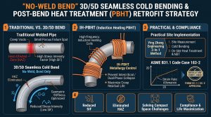
基於新規範的嚴苛要求,先進工程實務強烈建議導入「能彎不銲(Bend-instead-of-weld)」的核心改造工法1。該工法摒棄傳統的管件銲接,改採大型數控(CNC)彎管機,直接將直管母材透過物理冷作加工(Cold-Forming)彎折成曲率半徑達 3D(三倍管徑)或 5D(五倍管徑)的大型無縫彎管。 Based on the stringent requirements of the new codes, advanced engineering practices strongly recommend introducing the core modification method of “Bend-instead-of-weld”1. This method abandons traditional component welding, instead utilizing large Computer Numerical Control (CNC) bending machines to directly bend the straight base pipe material via physical Cold-Forming into large seamless bends with curvature radii reaching 3D (three times the pipe diameter) or 5D (five times the pipe diameter).
此技術在應力與壽命延長上具備三大壓倒性優勢:This technology possesses three overwhelming advantages in stress and life extension:
- 徹底消除銲縫與 HAZ:將高應力區的銲接接頭移至應力較低的直管段,完全拔除了第四型潛變破裂的萌生根源2。 Thorough Elimination of Welds and HAZ: Shifting the welded joints from high-stress zones to lower-stress straight pipe sections completely roots out the initiation source of Type IV creep cracking2.
- 法規 SIF 巨幅下降:根據 B31J 表格,3D/5D 大半徑彎管的應力強度因子極低,應力分佈平滑,能為系統在 CAESAR II 分析中爭取極大的 Liberal Allowable 裕度。
Massive Reduction in Code SIF: According to B31J tables, the stress intensification factors for 3D/5D large-radius bends are extremely low. The smooth stress distribution secures a substantial Liberal Allowable margin for the system in CAESAR II analysis. - 流體動力學優化:平滑的大曲率半徑可有效降低流體沖刷力,從而抵抗流體加速腐蝕(Flow-Accelerated Corrosion, FAC)10。同時避開流體渦流脫落導致斯楚哈爾數(Strouhal Number)落在0.4~0.5 之間的致命共振區間,有效緩解由閥門急關等操作引發的蒸汽錘(Steam Hammer)與冷凝水錘(Condensation-Induced Water Hammer)所造成的流固耦合(FSI)動態衝擊2。 Fluid Dynamics Optimization: The smooth, large radius of curvature effectively reduces fluid scouring forces, thereby resisting Flow-Accelerated Corrosion (FAC)10. At the same time, it avoids the fatal resonance zone where the Strouhal Number of fluid vortex shedding falls between 0.4 and 0.5, effectively mitigating the Fluid-Structure Interaction (FSI) dynamic impacts caused by Steam Hammer and Condensation-Induced Water Hammer induced by rapid valve closures2.
5.2 冷作加工應變控制與彎後熱處理 (PBHT) / 5.2 Strain Control in Cold Working and Post-Bend Heat Treatment (PBHT)
然而,「能彎不銲」並非沒有技術門檻。在極高厚徑比的大型 P91/P92 碳合金鋼管進行 3D/5D 彎折時,管材外弧段將承受龐大的張應力而變薄,內弧段則受壓應力而增厚。此過程伴隨高達 33.3% 的極限纖維伸長率(Extreme Fiber Elongation, EFE),導致嚴重的塑性變形與加工硬化(Strain Hardening)2。 However, “bend-instead-of-weld” is not without technical barriers. When bending large P91/P92 carbon alloy steel pipes with extremely high D/T ratios to 3D/5D, the outer arc of the pipe endures massive tensile stress and thins, while the inner arc endures compressive stress and thickens. This process is accompanied by an Extreme Fiber Elongation (EFE) as high as 33.3%, leading to severe plastic deformation and Strain Hardening2.
若未經妥善處理,加工硬化將導致金相組織嚴重畸變,破壞材料在 600°C 下的潛變抗力。因此,規範嚴格要求在此類高階鋼材冷作彎管成型後,必須執行精密的「彎後熱處理(Post-Bend Heat Treatment, PBHT)」。透過電腦溫控的感應加熱系統將管材升溫至次臨界或正火回火溫度區間,可使畸變的晶格重新結晶,恢復均勻的麻田散鐵組織,確保其機械性能完全符合 ASME B31.1 的規範要求2。 If left improperly treated, strain hardening will cause severe distortion of the metallographic structure, destroying the material’s creep resistance at 600°C. Therefore, codes strictly require the execution of precise “Post-Bend Heat Treatment (PBHT)” after the cold bending of such advanced steels. By utilizing a computer-temperature-controlled induction heating system to raise the pipe’s temperature to subcritical or normalizing and tempering ranges, the distorted lattice can recrystallize, restoring a uniform martensitic structure and ensuring its mechanical properties fully comply with ASME B31.1 code requirements2.
5.3 彈簧吊架系統之非線性重建 / 5.3 Nonlinear Reconstruction of Spring Hanger Systems
除管件替換外,支撐系統的改造亦是釋放熱應力的關鍵。在頻繁啟停下,原本設計用於恆定負載的彈簧吊架常因機構老化、連桿摩擦力或管線實際熱位移偏離設計值,產生高達 20% 的支撐力變異,甚至發生卡死。Besides replacing pipe components, modifying the support system is also crucial for releasing thermal stress. Under frequent startups and shutdowns, spring hangers originally designed for constant loads often experience supporting force variations up to 20%, or even seize, due to mechanism aging, linkage friction, or the pipeline’s actual thermal displacement deviating from design values.
在擬定改造策略時,工程師必須:When formulating modification strategies, engineers must:
- 依據 CAESAR II 重新計算的 OPE 與 SUS 工況位移,重新標定彈簧吊架的冷/熱態刻度(Cold/Hot Load Setting)1。 Re-calibrate the Cold/Hot Load Setting of spring hangers based on the displacements from the OPE and SUS cases re-calculated by CAESAR II1.
- 對於熱位移極端劇烈或產生支撐脫離(Lift-off)的節點,將傳統變力彈簧吊架(Variable Spring Hangers)升級替換為恆力彈簧吊架(Constant Effort Supports),以確保在整個熱循環行程中,施加於管系上的反作用力維持不變,徹底消除因為負載轉移(Load Transfer)而引發的二次局部應力集中。For nodes with extremely severe thermal displacement or those experiencing lift-off, upgrade and replace traditional Variable Spring Hangers with Constant Effort Supports. This ensures that the reactive force applied to the piping system remains constant throughout the entire thermal cycling stroke, thoroughly eliminating secondary local stress concentrations triggered by Load Transfer.
六、基於 AHP-MCDA 之前瞻性決策評估矩陣 / 6. Forward-Looking Decision Evaluation Matrix Based on AHP-MCDA
管線改造牽涉動輒數百萬至千萬美元的資本支出,同時需承擔發電機組停機(Downtime)帶來的龐大營收損失。為使電廠高階管理者能在眾多工程方案中做出具備科學根據之最佳化決策,本研究導入解析層級程序法(Analytical Hierarchy Process, AHP)構建多準則決策分析(MCDA)矩陣11。 Pipeline modifications entail capital expenditures often running into millions to tens of millions of dollars, alongside bearing immense revenue losses from power unit Downtime. To enable high-level plant managers to make scientifically-backed, optimized decisions among numerous engineering proposals, this study introduces the Analytical Hierarchy Process (AHP) to construct a Multi-Criteria Decision Analysis (MCDA) matrix11.
6.1 AHP 決策層級與權重建立 / 6.1 Establishment of AHP Decision Hierarchy and Weights
MCDA 將決策過程結構化,考量經濟、技術與環境等多維度指標11。本研究設定之評估準則及其相應之 AHP 專家權重配置如下: MCDA structures the decision-making process, considering multi-dimensional indicators encompassing economics, technology, and the environment11. The evaluation criteria set in this study and their corresponding AHP expert weight allocations are as follows:
- 資本支出 CAPEX (權重 25%) / CAPEX (Weight 25%):涵蓋管材採購、吊架更換、特殊施工(如冷作彎管、PBHT、現場銲接與非破壞檢測 NDT)之總合成本11。 Covers the total costs of pipe procurement, hanger replacement, and specialized construction (e.g., cold bending, PBHT, field welding, and NDT)11.
- 系統停機時間 Downtime (權重 20%) / Downtime (Weight 20%):物理改造所需的工作天數。CCPP 停機將直接影響電廠併網調度與營業收入,對短期經濟衝擊最大1。 The number of working days required for physical modification. CCPP downtime directly impacts the plant’s grid dispatch and operational revenue, presenting the greatest short-term economic shock1.
- B31J 法規合規與安全裕度 (權重 30%) / B31J Code Compliance and Safety Margin (Weight 30%):方案能否徹底消除 ASME B31.1 與 B31J 再驗證中的 SIF 超標熱點與持續應力警告,為電網安全營運之最高指導原則11。 Whether the proposal can thoroughly eliminate the SIF overload hotspots and sustained stress warnings from the ASME B31.1 and B31J re-evaluations, serving as the supreme guiding principle for safe grid operation11.
- 潛變殘餘壽命延長 Creep Life Extension (權重 25%) / Creep Life Extension (Weight 25%):基於 LMP 預測,方案對消除 HAZ Type IV 潛變破壞及延緩材料退化之長線資產管理效益11。 Based on LMP predictions, the proposal’s long-term asset management benefits in eliminating HAZ Type IV creep damage and delaying material degradation11.
6.2 方案層 (Alternatives) 比較與 VIKOR 綜合妥協分析 / 6.2 Comparison of Alternatives and VIKOR Comprehensive Compromise Analysis
我們針對 CCPP 管線提出三套典型處置方案,並透過 MCDA 矩陣進行評分比對。We propose three typical disposition alternatives for CCPP pipelines and score/compare them using the MCDA matrix.
表 1:CCPP 高溫高壓管系改造策略 AHP-MCDA 決策評估矩陣/Table 1: AHP-MCDA Decision Evaluation Matrix for Modification Strategies of High-Temperature and High-Pressure Piping in CCPP
| 評估準則 (AHP權重) / Evaluation Criteria (AHP Weight) | 方案 A:維持現狀 / 加強 NDT 監測 / Alt A: Status Quo / Enhanced NDT | 方案 B:吊架最佳化與局部切割重銲 / Alt B: Hanger Optimization & Local Rewelding | 方案 C:全面「能彎不銲」3D/5D冷彎改造 / Alt C: Comprehensive “Bend-instead-of-weld” 3D/5D Cold Bending | 方案效益解析與力學關聯 / Benefit Analysis and Mechanical Relevance |
| 資本支出 CAPEX (25%) | 評分:9 (成本極低) / Score: 9 (Extremely low cost) | 評分:6 (中等,含吊架更換) / Score: 6 (Moderate, includes hanger replacement) | 評分:3 (初期成本極高,需特製彎管) / Score: 3 (Extremely high initial cost, custom bends needed) | 方案 C 需大規模重置成本,但方案 A 隱含未來無預警破管的極端災難性成本11。 / Alt C requires massive replacement costs, but Alt A hides extreme catastrophic costs of future unheralded ruptures11. |
| 停機時間 Downtime (20%) | 評分:9 (歲修期間無縫銜接) / Score: 9 (Seamless integration during turnaround) | 評分:5 (局部停機約數週) / Score: 5 (Local downtime of several weeks) | 評分:2 (需長時間拆卸與現場 PBHT) / Score: 2 (Long removal time and field PBHT) | 方案 C 對當年度發電排程衝擊最劇,需前置周密計畫。 / Alt C poses the severest impact on the year’s generation schedule, requiring meticulous upfront planning. |
| B31J 安全裕度 Safety Margin (30%) | 評分:1 (持續違規,存在高應力盲點) / Score: 1 (Continuous violation, high-stress blind spots exist) | 評分:5 (邊緣及格,僅改善系統力矩) / Score: 5 (Marginally passes, only improves system moments) | 評分:10 (優,徹底抹除幾何高 SIF 熱點) / Score: 10 (Excellent, thoroughly erases geometric high-SIF hotspots) | 唯有方案 C 能從根本上改變幾何剛度矩陣,符合 B31J 解耦要求1。 / Only Alt C fundamentally alters the geometric stiffness matrix to meet B31J decoupling requirements1. |
| 潛變壽命延長 Creep Life Ext. (25%) | 評分:1 (加速劣化,隨時面臨破管) / Score: 1 (Accelerated degradation, impending rupture) | 評分:4 (微幅延長,延緩整體崩塌) / Score: 4 (Minor extension, delays total collapse) | 評分:10 (極佳,消除潛變脆弱區 HAZ) / Score: 10 (Outstanding, eliminates creep-vulnerable HAZ) | 根據 LMP,消除銲縫使局部當量應力下降,壽命將呈對數級別延長。 / Per LMP, eliminating welds lowers local equivalent stress, extending life logarithmically. |
| 加權總和得分 / Weighted Total Score | 4.60 (不建議 / Not recommended) | 5.00 (短期妥協解 / Short-term compromise) | 6.65 (長期最佳解,VIKOR首選 / Long-term optimum, VIKOR top choice) | 在極端調峰需求下,方案 C 是確保電廠未來數十年安全營運之唯一根本之道6。 / Under extreme peaking demands, Alt C is the only fundamental way to ensure decades of safe plant operations6. |
(註:評分採 1-10 分制,分數愈高代表在該項目之表現愈佳/愈有利)(Note: Scoring uses a 1-10 scale; a higher score indicates better/more favorable performance in that metric)
根據 MCDA 分析,若僅考量短期資本支出與發電效益,管理層容易傾向方案 A 或 B。然而,將權重置於長期安全裕度與潛變壽命延長後(如 VIKOR 妥協最佳化分析所建議),方案 C(全面冷作彎管改造)儘管面臨高 CAPEX 與長 Downtime 的挑戰,最終卻能取得最高的加權總分。According to the MCDA analysis, if only considering short-term capital expenditures and generation benefits, management might easily lean towards Alternatives A or B. However, once placing weight on long-term safety margins and creep life extension (as suggested by the VIKOR compromise optimization analysis), Alternative C (comprehensive cold bending modification) ultimately secures the highest weighted total score, despite facing challenges of high CAPEX and long Downtime.

七、實務工程管理與三合一工法之深度決策視角 / 7. In-Depth Decision Perspective of Practical Engineering Management and the Three-in-One Method
將 B31J 理論與有限元素分析轉化為可執行的廠務現場工程,仰賴跨單位的緊密協同。本章節探討不同工程角色在面對高能管線改造時的核心考量,並論證導入「三合一工法」在確保法規合規與冶金安全上的無可取代性。Translating B31J theory and finite element analysis into executable plant on-site engineering relies on close, cross-departmental collaboration. This chapter explores the core considerations of various engineering roles when facing high-energy piping modifications, and argues the irreplaceability of introducing the “Three-in-One Method” in ensuring regulatory compliance and metallurgical safety.
7.1 業主與廠務管理者之營運決策與生命週期管理 / 7.1 Operational Decisions and Life Cycle Management from the Perspective of Owners and Plant Managers
從發電廠業主(Owner)與廠務工程(Plant Engineering)管理者視角出發,高溫高壓管線的維護管理核心在於「降低非計畫性停機(Forced Outage)風險」與「極大化資產生命週期」。傳統的 1.5D 銲接彎頭不僅在高溫環境下極易萌生第四型潛變破裂,其銲道幾何突變處亦容易成為流體加速腐蝕(FAC)的脆弱點。From the perspectives of the power plant Owner and Plant Engineering managers, the core of high-temperature and high-pressure piping maintenance and management lies in “reducing the risk of Forced Outages” and “maximizing the asset life cycle.” Traditional 1.5D welded elbows are not only highly susceptible to initiating Type IV creep cracking in high-temperature environments, but the abrupt geometric changes at their welds also easily become vulnerable points for Flow-Accelerated Corrosion (FAC).
透過導入「能彎不銲」策略,以物理冷作彎管取代傳統電銲,能徹底拔除幾何高應力區的銲縫。這不僅能大幅提升結構完整性設計、優化傳遞至汽輪機的管口負載,更為高能管線系統的長期生命週期管理及未來的數位孿生(Digital Twin)演進提供了穩固的實務基礎。By introducing the “bend-instead-of-weld” strategy and replacing traditional arc welding with physical cold-formed bends, the welds in geometric high-stress zones can be thoroughly uprooted. This not only significantly enhances structural integrity design and optimizes nozzle loads transmitted to the steam turbine, but also provides a solid practical foundation for the long-term life cycle management and future Digital Twin evolution of high-energy piping systems.
7.2 EPC 承包商之空間佈置設計與合規實務 / 7.2 Spatial Layout Design and Compliance Practices of EPC Contractors
對於 EPC(工程、採購、建造)設計單位而言,3D/5D 大半徑冷作彎管的空間佈置(Spatial Layout)是一大挑戰。其所需的物理足跡遠大於傳統 1.5D 彎頭,要求配管工程師在初期設計階段就必須進行極度精密的管線路徑規劃12。 For EPC (Engineering, Procurement, and Construction) design units, the Spatial Layout of 3D/5D large-radius cold bends presents a major challenge. The physical footprint they require is far larger than that of traditional 1.5D elbows, demanding that piping engineers conduct extremely precise pipe routing plans during the initial design phase12.
然而,大半徑彎管能帶來顯著的流體動力學優勢,有效降低系統壓降,避開流體渦流脫落導致斯楚哈爾數落在 0.4~0.5 的致命共振區間,有效抑制流固耦合(FSI)引發的振動風險。在合規實務上,具備數位履歷的冷作彎管,能協助 EPC 廠商快速且無爭議地簽署 ASME B31.1 規範所要求的 Form CC-2(針對預製管段與管件組件的合規證明)與 Form CC-1(完整管線系統的最終合規證明),從而大幅降低工程驗收與移交風險10。 However, large-radius bends bring significant fluid dynamic advantages, effectively reducing system pressure drops, and avoiding the fatal resonance range where the Strouhal Number from fluid vortex shedding falls between 0.4 and 0.5, thus effectively suppressing the vibration risks induced by Fluid-Structure Interaction (FSI). In terms of compliance practices, cold bends equipped with digital resumes assist EPC firms in quickly and undisputedly signing the Form CC-2 (compliance certification for prefabricated pipe segments and component subassemblies) and Form CC-1 (final compliance certification for the complete piping system) required by the ASME B31.1 code, thereby drastically reducing engineering acceptance and handover risks10.
7.3 協力廠商之技術升級與因應策略 / 7.3 Technological Upgrades and Coping Strategies of Subcontractors
面對 2026 版 ASME B31.1 及 B31J 規範的強制導入,冷作彎管施作協力廠商(Subcontractors)面臨著不容迴避的技術轉型壓力。單純提供標準化 1.5D 銲接彎頭的傳統模式已無法滿足新法規對低週期疲勞與應力強度因子的嚴苛要求2。 Facing the mandatory introduction of the 2026 editions of the ASME B31.1 and B31J codes, cold bending subcontractors face an unavoidable pressure for technological transformation. The traditional model of merely supplying standardized 1.5D welded elbows can no longer satisfy the stringent requirements for low-cycle fatigue and stress intensification factors dictated by the new codes2.
協力廠商必須實施深度的技術升級,建立能夠嚴格控制成型應變率、處理高極限纖維伸長率的製造量能,並配備精密的熱處理設備。透過主動導入整合型的高階工法,協力廠商能確保其出廠的冷作管件完全對接 ASME 規範要求,轉型為發電業不可或缺的技術與策略夥伴2。 Subcontractors must implement deep technological upgrades, establishing manufacturing capabilities that can strictly control forming strain rates and handle high extreme fiber elongations, as well as equipping themselves with precise heat treatment facilities. By proactively introducing integrated advanced methods, subcontractors can ensure their outgoing cold-formed pipe components perfectly align with ASME code requirements, transforming into indispensable technical and strategic partners for the power generation industry2.
7.4 導入潁璋工程「能彎不銲」三合一工法之核心價值 / 7.4 Core Value of Introducing the Ying-Zhang Engineering “Bend-instead-of-weld” Three-in-One Method
導入潁璋工程(Ying-Zhang Engineering)所提倡的「三合一工法」(3D/5D CNC 大半徑冷作彎管 + IH-PBHT 單管感應亞臨界彎後熱處理 + QR Code 雲端數位履歷),是發揮大半徑優勢的唯一解方。此工法管理的核心價值在於徹底落實「能彎不銲」的設計理念,從源頭將易受流體沖刷與疲勞破壞的銲縫轉化為連續平滑的母材彎曲段。針對高能管線,此工法的執行不僅是製造手段的升級,更是嚴格對接 ASME B31.1 與 B31J 規範的合規性展現2。 Introducing the “Three-in-One Method” (3D/5D CNC large-radius cold bends + IH-PBHT single-pipe induction subcritical post-bend heat treatment + QR Code cloud digital resume) advocated by Ying-Zhang Engineering is the only solution to unleash the advantages of large radii. The core management value of this method lies in the thorough implementation of the “bend-instead-of-weld” design philosophy, transforming welds that are susceptible to fluid scouring and fatigue damage into continuous, smooth base material curved sections straight from the source. For high-energy piping, the execution of this method is not only an upgrade in manufacturing techniques but also a demonstration of strict compliance alignment with ASME B31.1 and B31J codes2.
該工法由三大技術支柱構成,完美契合 ASME 規範精神,藉由台中電廠與興達電廠等大型專案中實作經驗累積並且開發「能彎不銲」三合一工法12: This method is composed of three major technical pillars, perfectly echoing the spirit of ASME codes, accumulating practical implementation experience through large-scale projects such as the Taichung Power Plant and Hsinta Power Plant, thereby developing the “bend-instead-of-weld” Three-in-One Method12:
- 高精度 CNC 數控大半徑冷彎:以精密機械力學彎折 3D/5D 管件,徹底消除環口銲道,從源頭抹除應力集中與潛變破裂的萌生點2。 High-Precision CNC Large-Radius Cold Bending: Utilizing precision mechanical dynamics to bend 3D/5D pipe components thoroughly eliminates circumferential girth welds, erasing the initiation points of stress concentration and creep rupture from the source2.
- IH-PBHT 單管感應亞臨界彎後熱處理:採用單管精確溫控進行局部退火,精準掌控 P91/P92 等高階合金鋼的微觀組織修復,避免二次熱處理所引發的潛變退化。
IH-PBHT Single-Pipe Induction Subcritical Heat Treatment: Employing single-pipe precise temperature control for local annealing accurately dictates the microstructural repair of advanced alloy steels like P91/P92, avoiding creep degradation induced by secondary heat treatments. - QR Code 雲端數位履歷:將材料試驗數據、幾何參數檢測與熱處理溫度曲線無縫綁定至雲端,提供絕對不可竄改的管線最終生產報告,確保全流程品質追溯與法規透明度。 QR Code Cloud Digital Resume: Seamlessly binding material test data, geometric parameter inspections, and heat treatment temperature curves to the cloud provides an absolutely unalterable final production report for the piping, ensuring full-process quality traceability and regulatory transparency.
7.5 深度解析:應變率 (5%~20%) 放寬與 IH-PBHT 冶金控制 / 7.5 In-Depth Analysis: Relaxation of Strain Rate (5%-20%) and IH-PBHT Metallurgical Control
針對高階潛變增強型鐵素體鋼(如 P91、P92 鋼材)在冷作加工中所面臨的冶金瓶頸,ASME 規範(如 B31.1 Code Case 183-2)提供了一項極具實務價值的放寬條款:當冷作彎管的成型應變率(Strain Rate, ϵ)介於5%≤ϵ≤20% 時,法規允許實施局部次臨界回火熱處理(Subcritical Tempering,溫度限制在 730°C 至 775°C 之間),而無須對全管段進行高溫正常化與回火(Normalizing and Tempering)2。 Regarding the metallurgical bottlenecks faced by advanced creep-strength enhanced ferritic steels (such as P91 and P92) during cold working, ASME codes (e.g., B31.1 Code Case 183-2) provide a relaxation clause of immense practical value: when the forming Strain Rate (ϵ) of the cold bend falls between 5%≤ϵ≤20%, the code permits the implementation of local Subcritical Tempering (temperature limited between 730°C and 775°C) without the need to perform high-temperature Normalizing and Tempering on the entire pipe segment2.
此一應變率的放寬對冶金控制意義非凡。在傳統的管線銲接與其後續的銲後熱處理(PWHT)中,銲接耗材(Filler Metal)常添加鎳(Ni)與錳(Mn)以改善韌性;然而,這兩種沃斯田鐵穩定元素會顯著壓低材料的下臨界轉變溫度(AC1)。研究表明,當銲材中的 Ni+Mn 總量超過 1.0% 至 1.5% 時,AC1 可能下探至 760°C 甚至更低。若現場熱處理的溫控稍有不慎,跨越了局部材料的 AC1 線進入兩相區(Intercritical Region),冷卻後將產生極端硬脆且易碎的鮮明麻田散鐵(Fresh Martensite),此類缺陷極難透過常規非破壞檢測(NDE)察覺。The relaxation of this strain rate holds extraordinary significance for metallurgical control. In traditional pipe welding and its subsequent Post-Weld Heat Treatment (PWHT), the Filler Metal often contains additions of Nickel (Ni) and Manganese (Mn) to improve toughness; however, these two austenite-stabilizing elements significantly depress the material’s lower critical transformation temperature (AC1). Research indicates that when the total Ni+Mn content in the filler metal exceeds 1.0% to 1.5%, the AC1 may drop to 760°C or even lower. If the temperature control during on-site heat treatment is slightly careless, crossing the local material’s AC1 line and entering the Intercritical Region, extreme hard and brittle Fresh Martensite will form upon cooling. Such defects are extremely difficult to detect via conventional Non-Destructive Examination (NDE).
採用無銲接耗材干擾的冷作彎管,搭配 IH-PBHT 技術,能精準控制在此次臨界(730°C – 775°C)的狹窄回火溫度窗口內。這不僅完美避開了 AC1 溫度下沉與兩相區崩潰的致命風險,更成功修復了冷彎帶來的加工硬化,將材料的拉森-米勒參數(LMP)徹底恢復至安全的預期壽命區間,確保高溫調峰運轉下的疲勞韌性與極致安全性2。 Utilizing cold bends free from filler metal interference, coupled with IH-PBHT technology, allows for precise control within this narrow subcritical tempering temperature window (730°C – 775°C). This not only perfectly avoids the fatal risks of AC1 temperature depression and intercritical region collapse but also successfully repairs the strain hardening induced by cold bending. It thoroughly restores the material’s Larson-Miller Parameter (LMP) to a safe expected life span, ensuring fatigue toughness and ultimate safety under high-temperature peaking operations2.
八、結論 / 8. Conclusion
ASME B31J 規範的全面強制化與 B31.1 厚壁 Lamé 方程式的修正,徹底推翻了統治管線工程界逾半世紀的 Appendix D 經驗法則,在業界掀起了一場無可避免的「應力分析革命」。此一法規演進絕非僅是軟體參數的微調,而是精確揭示了既有高能管線在複雜三維空間中因平面內、平面外與扭轉力矩耦合而長期被隱藏的真實極端應力狀態。The mandatory implementation of the ASME B31J code and the modification of the B31.1 thick-wall Lamé equations have completely overthrown the Appendix D empirical rules that governed the piping engineering industry for over half a century, sparking an inevitable “stress analysis revolution” across the sector. This regulatory evolution is by no means a mere fine-tuning of software parameters; rather, it precisely uncovers the true extreme stress states in existing high-energy piping that were long hidden due to the coupling of in-plane, out-of-plane, and torsional moments in complex 3D space.
本研究結合 CAESAR II 應力分析平台與 Larson-Miller 參數(LMP)潛變壽命模型,對現代 CCPP 廠在極端調峰運轉下的 P91/P92 高壓蒸汽管線進行了深度驗證。分析顯示,採用舊規範設計的傳統電銲接頭與三通,在新規範檢視下往往存在嚴重的持續應力與熱疲勞超標問題;其微觀結構加速退化,硬度顯著下降,實際殘餘壽命遠低於原始設計預期,隨時面臨第四型潛變破裂的致命威脅。Combining the CAESAR II stress analysis platform with the Larson-Miller Parameter (LMP) creep life model, this study conducted an in-depth validation of P91/P92 high-pressure steam pipelines in modern CCPP plants under extreme peaking operations. The analysis shows that traditional welded joints and tees designed using legacy codes often exhibit severe sustained stress and thermal fatigue overload issues when scrutinized under the new codes. Their microstructures undergo accelerated degradation, hardness drops significantly, and the actual remaining life falls far below original design expectations, constantly facing the fatal threat of Type IV creep cracking.
為此,本報告提出以「能彎不銲」之 3D/5D 無縫冷作彎管技術搭配彎後熱處理(PBHT)的實體改造策略。此工法能從根本上改變管系幾何剛度、大幅降低局部應力強度因子(SIF),並徹底消除引發潛變孔洞的熱影響區(HAZ)。最後,從實務面探討,透過導入潁璋工程之「三合一工法」與 ASME B31.1 Code Case 183-2 之應變率放寬條款,不僅能協助 EPC 與廠務管理者解決複雜的空間佈置與合規(Form CC-1/CC-2)挑戰,更藉由精密的 IH-PBHT 冶金控制技術防範兩相區崩潰,確保了最佳的法規合規性、極大化潛變殘餘壽命,成為現代發電業應對極端營運挑戰的最佳戰略解答。To address this, the report proposes a physical modification strategy utilizing the “bend-instead-of-weld” 3D/5D seamless cold bending technology paired with Post-Bend Heat Treatment (PBHT). This method fundamentally alters the geometric stiffness of the piping system, drastically reduces local Stress Intensification Factors (SIF), and thoroughly eliminates the Heat-Affected Zones (HAZ) that trigger creep cavities. Finally, exploring from a practical standpoint, introducing Ying-Zhang Engineering’s “Three-in-One Method” and the strain rate relaxation clause of ASME B31.1 Code Case 183-2 not only assists EPC and plant managers in solving complex spatial layout and compliance (Form CC-1/CC-2) challenges but also prevents intercritical region collapse via precise IH-PBHT metallurgical control technology. This ensures optimal regulatory compliance and maximizes remaining creep life, emerging as the best strategic answer for the modern power generation industry in tackling extreme operational challenges.
參考文獻 / References
- ASME B31J-2023, https://www.asme.org/getmedia/6514398f-744e-445f-9ed6-2d6ef046707e/toc_b31j_2023.pdf
- SIF & Flexibility Factors — ASME B31J-2023 & NM.1 HDPE, https://pipingtoolset.com/tools/sif-flexibility-factors/
- ASME B31J: I & K Factors in Pipe Analysis, https://www.cortexsoftware.com.au/blog/understanding-asme-b31j-methods-i-factors-and-k-factors-in-piping-stress-analysis
- ASME-B31.1.pdf – Future Energy Steel, https://energy-steel.com/wp-content/uploads/2025/03/ASME-B31.1.pdf
- ASME B31J SIFs & k-Factors: Why B31.3 Deleted Appendix D, https://pipingtoolset.com/guides/b31j-stress-intensification-factors/
- Experimental Evaluation of the Markl Fatigue Methods and ASME, http://files.engineering.com/files/f4e5b1f1-477d-472f-a970-5d642d83b0e4/PVP2008-Hinnant_and_Paulin.pdf
- Stress Intensity Factor (SIF), Flexibility Factor: ASME B31.3 vs ASME, https://whatispiping.com/stress-intensity-factor-sif-flexibility-factor-asme-b-31j/
- 3 Stress Intensification Factors, https://www.littlepeng.com/single-post/2020/03/29/13-stress-intensification-factors
- 基於2026 ASME B31J 規範之CCPP 高能管線銲接彎頭與3D/5D 冷作, https://yz-pipe-bending.com.tw/%E5%9F%BA%E6%96%BC-2026-asme-b31j-%E8%A6%8F%E7%AF%84%E4%B9%8B-ccpp-%E9%AB%98%E8%83%BD%E7%AE%A1%E7%B7%9A%E9%8A%B2%E6%8E%A5%E5%BD%8E%E9%A0%AD%E8%88%87-3d-5d-%E5%86%B7%E4%BD%9C%E5%BD%8E%E7%AE%A1%E7%B5%90/
- ASME B31J 導入對高溫高壓動力管線(1)與製程管線(B31.3, https://yz-pipe-bending.com.tw/asme-b31j-
- Improving Stress Intensification and Flexibility Analysis with ASME, https://www.youtube.com/watch?v=hHzbt3KdiDg
- ASME B31.1-2024 Stress Intensification Factors (SIFs) — FAQ, https://pipingtoolset.com/faq/b311-stress-intensification-factors/