
一、 摘要 / I. Abstract
在全球能源轉型與電網調度的嚴苛要求下,現代複循環發電廠正朝向超高溫、高壓以及頻繁起停的調峰模式發展。此操作環境對廠區內的高能動力管線系統提出了前所未有的冶金與力學挑戰。傳統管線佈局高度仰賴短半徑銲接彎頭,然而此類幾何不連續且富含微觀冶金缺陷的組件,已成為電廠發生非預期停機甚至災難性破裂的主因。為解決此工程痛點,美國機械工程師學會(ASME)於 2024 至 2026 年版的 B31.1 與 B31J 規範中進行了深刻的典範轉移。本文深度剖析新規範全面廢除單一應力強度因子經驗公式、強制導入空間方向性彈性矩陣的核心演進;並探討針對冷彎成形過程,從「單一變形界限一律熱處理」框架過渡至「基於應變率階梯與疲勞性能分析」的彈性放寬機制。研究進一步從電銲銲道衍生的不可抗拒裂紋之微觀機制與工程臨界評估切入,結合產業多維度實務視角,全面論證 3D/5D 大半徑冷作彎管在取代傳統銲接彎頭後,於疲勞壽命增益、流體動力學最佳化與結構完整性表現上的全適用性與不可替代性。Under the stringent requirements of global energy transition and power grid regulation, modern Combined Cycle Power Plants (CCPP) are moving towards ultra-high temperature, high pressure, and frequent start-stop peak-shaving operational modes. This operating environment poses unprecedented metallurgical and mechanical challenges to the High-Energy Piping (HEP) systems within the plants. Traditional piping layouts rely heavily on short-radius welded elbows; however, these components, characterized by geometric discontinuities and microscopic metallurgical defects, have become the primary cause of unexpected plant shutdowns and even catastrophic ruptures. To address this engineering pain point, the American Society of Mechanical Engineers (ASME) initiated a profound paradigm shift in the 2024 to 2026 editions of the B31.1 and B31J codes. This paper deeply analyzes the core evolution of the new codes, which completely abolish the empirical single stress intensification factor formulas and mandatorily introduce a spatial directional elasticity matrix. Furthermore, it explores the flexible relaxation mechanism for the cold bending process, transitioning from a “single deformation limit with mandatory heat treatment” framework to a “strain rate tier and fatigue performance analysis-based” evaluation. By investigating the micro-mechanisms of irresistible cracks derived from weld seams and Engineering Critical Assessment (ECA), combined with multi-dimensional practical industry perspectives, this study comprehensively demonstrates the full applicability and irreplaceability of 3D/5D large-radius cold bends in replacing traditional welded elbows, highlighting their benefits in fatigue life extension, fluid dynamics optimization, and structural integrity.
二、 緒論與產業背景 / II. Introduction and Industry Background
現代複循環發電廠(Combined Cycle Power Plant, CCPP)在整合再生能源併網的過程中,肩負著極為關鍵的基載與調峰任務。為追求更高的熱效率與降低碳排放,超臨界與超超臨界水蒸氣循環系統的操作溫度與壓力屢創新高。在這樣極端的熱力學環境中,廠內的高能動力管線(High-Energy Piping, HEP)長期暴露於劇烈的熱膨脹、熱收縮以及內外壓交變載荷之下1。過去數十年間,管線工程師在進行三維佈局設計時,習慣性地大量採用 1.5D 規格的標準對銲彎頭(Welded Elbows)來實現管線轉向。這種設計雖然在工廠預製與空間壓縮上具備初始的便利性,卻在系統中埋下了無數個應力集中與冶金劣化的熱點。Modern Combined Cycle Power Plants (CCPP) shoulder crucial baseload and peak-shaving tasks in the process of integrating renewable energy into the grid. To achieve higher thermal efficiency and lower carbon emissions, the operating temperatures and pressures of supercritical and ultra-supercritical steam cycles continue to hit new highs. In such extreme thermodynamic environments, High-Energy Piping (HEP) inside the plant is chronically exposed to severe thermal expansion, thermal contraction, and alternating internal/external pressure loads1. Over the past decades, when designing 3D layouts, piping engineers habitually relied heavily on standard 1.5D welded elbows to achieve directional changes. Although this design offers initial convenience for shop prefabrication and space compression, it embeds countless hotspots of stress concentration and metallurgical degradation into the system.
隨著服役時間推移,業界逐漸發現,帶有環向電銲銲道(Girth Welds)的短半徑彎頭在經歷長期的熱機械疲勞(Thermo-mechanical fatigue)與高溫潛變(Creep)效應疊加後,極易誘發管壁減薄與微裂紋萌生,最終導致管線的突發性破裂1。這種破壞往往是災難性的,不僅造成嚴重工安事故,更使電廠面臨漫長且昂貴的非預期停機。問題的核心在於,傳統銲接彎頭將管線系統中幾何應力最集中的區域,與材料微觀組織最脆弱的銲接熱影響區(Heat-Affected Zone, HAZ)在物理空間上完全重疊。As service time progresses, the industry has increasingly found that short-radius elbows with girth welds, after enduring long-term thermo-mechanical fatigue superimposed with high-temperature creep effects, are highly prone to wall thinning and micro-crack initiation, ultimately leading to sudden pipe ruptures1. Such failures are often catastrophic, causing not only severe industrial safety accidents but also subjecting power plants to lengthy and expensive unplanned downtimes. The core of the problem lies in the fact that traditional welded elbows physically overlap the area of highest geometric stress concentration with the Heat-Affected Zone (HAZ), the most vulnerable microstructural region of the material.
為從根本上解決結構完整性危機,ASME 推動了半世紀以來最大幅度的規範修正。2024 年至 2026 年版的 ASME B31.1(動力管線規範)與 ASME B31J(管線組件應力強度因子與柔性因子規範)聯手建立了一套更為嚴格且貼近物理真實的評估框架4。新規範一方面透過引入有限元素分析級別的空間方向性應力矩陣,無情揭露了 1.5D 銲接彎頭在複雜載荷下的脆弱性;另一方面,則針對 3D 與 5D 大半徑冷作彎管(Cold Bending)的製造與熱處理要求,釋出基於應變率(5% 至 20%)的科學放寬機制3。這一收一放之間,明確指引了未來高能動力管線「以彎代銲」的必然發展路徑。本文將深入解析此規範演進的理論基礎,並透過微觀冶金學與斷裂力學視角,全面論證 3D/5D 冷作彎管在現代 CCPP 中的應用價值。To fundamentally resolve this structural integrity crisis, ASME pushed forward the most substantial code revision in half a century. The 2024 to 2026 editions of ASME B31.1 (Power Piping Code) and ASME B31J (Standard for Stress Intensification Factors and Flexibility Factors for Piping Components) jointly established a stricter evaluation framework that closely aligns with physical reality4. On one hand, by introducing a Finite Element Analysis (FEA)-grade spatial directional stress matrix, the new code mercilessly exposes the vulnerability of 1.5D welded elbows under complex loads; on the other hand, it releases a scientific relaxation mechanism based on strain rates (5% to 20%) for the manufacturing and heat treatment requirements of 3D and 5D large-radius cold bends3. This dual approach clearly points to the inevitable future trend of replacing welding with bending (“Bending instead of welding”) in high-energy power piping. This paper will deeply analyze the theoretical foundation of this code evolution and comprehensively demonstrate the application value of 3D/5D cold bends in modern CCPPs through the lenses of micro-metallurgy and fracture mechanics.
三、 ASME B31.1 與 B31J 規範框架之典範轉移 / III. Paradigm Shift of ASME B31.1 and B31J Code Frameworks
在探討冷作彎管的力學優勢之前,必須先理解主導管線應力分析的規範框架如何在 2026 年完成歷史性的典範轉移。管線應力分析的準確性直接決定了發電廠生命週期內的安全性,而在過去數十年間,工程界普遍依賴 A.R.C. Markl 於 1950 年代所建立的疲勞測試模型。Before discussing the mechanical advantages of cold bending, it is essential to understand how the code framework governing piping stress analysis achieved a historic paradigm shift by 2026. The accuracy of piping stress analysis directly determines the safety of a power plant throughout its lifecycle, and for decades, the engineering community universally relied on the fatigue testing models established by A.R.C. Markl in the 1950s.
3.1 傳統 Markl 理論的結構性侷限與附錄 D 的退場 / 3.1 Structural Limitations of Traditional Markl Theory and the Phase-out of Appendix D
傳統的 ASME B31 規範體系中,管線組件的應力評估主要依賴 B31.1 附錄 D(Appendix D)所提供的封閉式經驗公式。這些公式(如 i=0.9/h2/3)基於 4 吋標準壁厚無縫碳鋼管的低週期疲勞實驗推導而來。然而,當這些半世紀前的經驗公式被強行套用於現代 CCPP 中常見的高溫高壓、大口徑、薄壁化且材質多樣的高階合金鋼管線時,暴露出極大的保守性與理論盲點5。In the traditional ASME B31 code system, the stress evaluation of piping components mainly relied on the closed-form empirical formulas provided in ASME B31.1 Appendix D. These formulas (e.g., i=0.9/h2/3) were derived from low-cycle fatigue tests on 4-inch standard-wall seamless carbon steel pipes. However, when these half-century-old empirical formulas were forcibly applied to modern CCPP piping—characterized by high temperatures, high pressures, large diameters, thin walls, and diverse high-grade alloy steels—they exposed profound conservativeness and theoretical blind spots5.
傳統理論的最大缺陷在於,它對管件強行賦予單一的應力強度因子(Stress Intensification Factor, SIF 或 i 值),完全未區分三維空間中不同方向彎矩的破壞力差異。在真實物理世界中,面內彎矩(使彎管兩端靠攏或張開)會引發管截面的橢圓化現象(Ovalization),而面外彎矩則會在特定幾何不連續處產生極高的局部應力。此外,舊版規範長年忽略扭轉力矩對剪應力的貢獻,一律預設扭轉 SIF 為 1.0,這在複雜的三維熱膨脹位移中嚴重低估了疲勞風險5。The biggest flaw in the traditional theory was that it forcibly assigned a single Stress Intensification Factor (SIF, or i-factor) to a fitting, failing completely to differentiate the destructive effects of bending moments in various three-dimensional directions. In the real physical world, in-plane bending moments (which push the ends of a bend together or apart) trigger cross-sectional ovalization, while out-of-plane moments generate extremely high local stresses at specific geometric discontinuities. Furthermore, the legacy codes ignored the contribution of torsional moments to shear stress for years, uniformly presetting the torsional SIF to 1.0, which severely underestimated fatigue risks under complex 3D thermal expansion displacements5.
鑑於此,ASME B31.1 於 2024 年版正式且徹底地刪除 Mandatory Appendix D,並將所有應力強度因子與柔性因子的計算源頭唯一指向 ASME B31J 標準。此規定在 2026 年的新建工程與應力分析模型中具備絕對的強制力,標誌著管線工程界正式告別單一經驗公式時代4。In light of this, the 2024 edition of ASME B31.1 officially and completely deleted Mandatory Appendix D, uniquely pointing the source for all SIFs and flexibility factors to the ASME B31J standard. This requirement will hold absolute mandatory force in new construction projects and stress analysis models by 2026, marking the piping engineering community’s formal farewell to the era of single empirical formulas4.
3.2 B31J 空間方向性應力矩陣的全面強制化 / 3.2 Mandatory Implementation of the B31J Spatial Directional Stress Matrix
ASME B31J-2023 標準基於嚴謹的有限元素分析與大規模實體疲勞測試,針對空間中的三個自由度分別定義了獨立的應力強度因子:面內(ii)、面外(io)以及扭轉(it)4。這種方向性拆解(Direction-Split)矩陣模型,使管線系統在承受地震、水錘或熱膨脹時,能夠精確捕捉每一處節點在不同向量軸上的真實受力狀態。Based on rigorous Finite Element Analysis (FEA) and large-scale physical fatigue testing, the ASME B31J-2023 standard defines independent stress intensification factors for the three degrees of freedom in space: in-plane (ii), out-of-plane (io), and torsional (it)4. This direction-split matrix model enables piping systems to accurately capture the true stress state at every node along different vector axes when subjected to seismic events, water hammer, or thermal expansion.
在 B31.1 的管線壓力與應力設計準則中,針對不同類型的載荷實施了分級評估機制。對於持續性載荷(如自重與內壓),B31.1 引入了持續應力指數(Sustained Stress Index, I),定義為對應 B31J SIF 值的 0.75 倍與 1.00 兩者間之較大值4。然而,在評估最具破壞性的疲勞位移應力範圍時,規範則明確要求直接使用未經任何折減的 B31J SIF 數值(ii , io , it),並將其投入平方和之平方根(SRSS)方程式中進行嚴格檢核。這種分析機制的轉換在業界引發了顯著的「應力分析休克(Stress Analysis Shock)」:許多在舊版規範下勉強合格的 1.5D 銲接彎頭,在 B31J 的精細檢視下紛紛暴露出應力嚴重超標的問題8。為了重新符合新規範,設計端被迫從幾何源頭尋求改善,直接推動了 SIF 值更低、應力過渡更平順的 3D 或 5D 冷作彎管成為市場主流。In the piping pressure and stress design criteria of B31.1, a tiered evaluation mechanism is implemented for different types of loads. For sustained loads (such as deadweight and internal pressure), B31.1 introduced the Sustained Stress Index (I), defined as the greater of 0.75 times the corresponding B31J SIF value or 1.004. However, when evaluating the most destructive fatigue displacement stress range, the code explicitly requires the direct use of unreduced B31J SIF values (ii , io , it) inputted into the Square Root of the Sum of the Squares (SRSS) equation for strict verification. This shift in the analysis mechanism triggered a significant “Stress Analysis Shock” in the industry: many 1.5D welded elbows that barely passed under the legacy code were suddenly exposed as having severe stress over-limit issues under B31J’s granular inspection8. To regain compliance with the new code, designers were forced to seek improvements from the geometric source, directly propelling 3D or 5D cold bends—which feature lower SIF values and smoother stress transitions—into the market mainstream.
3.3 壓力設計與安全裕度的跨規範比較 / 3.3 Cross-Code Comparison of Pressure Design and Safety Margins
要全面理解 B31.1 對管線結構強度的嚴苛要求,可將其與化學及煉油製程領域廣泛使用的 ASME B31.3(製程管線規範)進行對比。這兩套規範在安全裕度的哲學上存在根本差異,直接影響了冷作彎管的設計壁厚與疲勞容忍度。To fully understand B31.1’s stringent requirements for piping structural strength, it is instructive to compare it with ASME B31.3 (Process Piping Code), which is widely used in chemical and refinery processing fields. These two codes have fundamental differences in their safety margin philosophies, directly impacting the design wall thickness and fatigue tolerance of cold bends.
| 比較參數 Comparison Parameter | ASME B31.1 (動力管線 Power Piping) | ASME B31.3 (製程管線 Process Piping) |
| 核心設計導向 Core Design Orientation | 高溫高壓蒸汽循環之絕對可靠性與長期結構完整性 Absolute reliability and long-term structural integrity for high-temp/high-pressure steam cycles7 | 廠區複雜流體風險管理與建廠經濟靈活性 Risk management of complex plant fluids and economic flexibility7 |
| 基本安全係數 Basic Safety Factor | 約 4.0(極端保守設計,以防範高溫潛變為主) ~4.0 (Extremely conservative design, primarily to prevent high-temp creep)8 | 約 3.0(在成本效益與運轉性能間尋求平衡) ~3.0 (Striking a balance between cost-efficiency and operational performance)13 |
| 縱向壓力應力 Longitudinal Pressure Stress (Slp) | 全面廢除薄壁近似,改採厚壁圓筒 Lamé 精確方程式 Completely abolished thin-wall approximation, adopting the exact thick-wall cylinder Lamé equation | 傳統薄壁近似理論的延伸,輔以特定補償 Extension of traditional thin-wall approximation theory, supplemented with specific allowances |
| 熱處理強制極限值 Mandatory Heat Treatment Limits | 高度指令性,依壁厚物理尺寸判定(如壁厚達 19 mm 即強制要求) Highly prescriptive, determined by physical wall thickness (e.g., mandatory if thickness reaches 19 mm)6 | 賦予業主裁量權,視局部纖維伸長率與硬度彈性決定 Grants owner discretion, flexibly determined based on local fiber elongation and hardness6 |
在 B31.1 規範語境下,高達 4.0 的安全係數與新導入的 Lamé 厚壁方程式,意味著動力管線的基礎壓力設計極度保守。在強大內部蒸汽壓力與高溫熱膨脹的雙重箝制下,系統內部的剩餘應力裕度極度緊縮。因此,唯一能有效降低系統總應力、避免超標的手段,便是利用大半徑冷作彎管來降低節點的 SIF 與柔性因子,這成為符合 B31.1 高標準的最佳解方。In the context of the B31.1 code, a high safety factor of 4.0 and the newly introduced Lamé thick-wall equation mean that the foundational pressure design of power piping is extremely conservative. Constrained dually by massive internal steam pressure and high-temperature thermal expansion, the remaining stress margin within the system is severely tightened. Therefore, the only effective means to reduce total system stress and avoid exceeding limits is to utilize large-radius cold bends to lower nodal SIFs and flexibility factors, making this the optimal solution for meeting B31.1’s high standards.
四、 冷彎成形之物理幾何變化與應變率放寬機制 / IV. Physical Geometric Changes of Cold Bending and Strain Rate Relaxation Mechanism
冷作彎管技術是將直管在室溫或亞臨界溫度下,透過機械力矩強制彎曲至特定半徑的製程。為確保冷彎後的管線仍能滿足高溫高壓環境的嚴苛要求,必須深刻理解其物理幾何變化與規範對應的補償與放寬機制。Cold bending technology is a process wherein straight pipes are forcibly bent to a specific radius using mechanical torque at room or subcritical temperatures. To ensure that the cold-bent piping still meets the stringent requirements of high-temperature and high-pressure environments, one must deeply understand the physical geometric changes and the code’s corresponding compensation and relaxation mechanisms.
4.1 冷彎成形的幾何變異與壁厚減薄補償 / 4.1 Geometric Variation of Cold Bending and Wall Thinning Compensation
當直管受力彎曲時,管截面的中性軸會向內弧側偏移,導致外弧側壁厚減薄、內弧側受壓增厚以及圓形截面橢圓化畸變3。隨之而來的是金屬晶格內部差排密度劇增,引發應變硬化,這雖提高了局部降伏強度,卻也犧牲了延展性並產生複雜的殘餘應力場14。When a straight pipe is subjected to bending, the neutral axis of the cross-section shifts toward the intrados, causing wall thinning at the extrados, compression thickening at the intrados, and ovalization of the circular cross-section3. Consequently, dislocation density inside the metal lattice surges, triggering strain hardening; while this increases local yield strength, it sacrifices ductility and generates a complex residual stress field14.
為確保減薄的外弧側仍能承受額定內壓,ASME B31.1 規定了嚴格的內壓最小壁厚(tm)計算公式,並制定了不同彎曲半徑的訂料厚度補償係數。例如:To ensure the thinned extrados can still withstand the rated internal pressure, ASME B31.1 dictates strict calculation formulas for the minimum required wall thickness (tm) and establishes ordering thickness compensation factors for various bending radii. For instance:
- 3D 彎管:規範要求直管壁厚必須達到 1.25 tm(增加 25% 餘裕)。3D Bends: The code requires the straight pipe wall thickness to reach 1.25 tm (a 25% allowance increase).
- 5D 彎管:外弧拉伸大幅減緩,僅要求 1.08 tm(僅需 8% 補償餘裕)。5D Bends: Extrados stretching is significantly mitigated, requiring only 1.08 tm (an 8% compensation allowance).
從工程經濟與製造極限分析,5D 冷作彎管僅需 8% 的壁厚補償,意味著電廠可採用標準規格管材進行彎曲,無需耗資訂製超厚壁管;同時其曲率半徑亦不會佔用過大的廠區空間。因此,5D 冷作彎管在成本、成形難度與佈局效率間取得了完美的平衡。Analyzing from the perspectives of engineering economics and manufacturing limits, 5D cold bends require only an 8% wall thickness compensation. This means power plants can use standard specification pipes for bending without spending heavily on custom ultra-thick-walled pipes; meanwhile, its curvature radius does not consume excessive plant space. Therefore, 5D cold bends strike a perfect balance between cost, forming difficulty, and layout efficiency.
4.2 應變率的數學定義與 3D/5D 彎管的區間落點 / 4.2 Mathematical Definition of Strain Rate and the Range Placement of 3D/5D Bends
冷彎過程對材料內部組織的破壞程度可透過塑性應變率(ϵ)量化。計算公式為:The degree of damage to the material’s internal microstructure during the cold bending process can be quantified by the plastic strain rate (ϵ). The formula is:
ϵ=r/R=Do/2R×100%
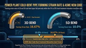
將發電廠主流應用的冷作彎管代入,3D 彎管的成形應變率約為 16.67%,而 5D 彎管則為 10.0%。計算結果顯示,無論 3D 或 5D 彎管,其成形應變率皆精準落於 5% 至 20% 的過渡區間內,這正是 ASME 新規範制定熱處理放寬機制的核心焦點。By applying the mainstream cold bends used in power plants, the forming strain rate for 3D bends is approximately 16.67%, while for 5D bends it is 10.0%. The calculation results show that both 3D and 5D bends have forming strain rates that fall precisely within the transitional range of 5% to 20%, which is the core focus of the new ASME code in establishing heat treatment relaxation mechanisms.
4.3 規範演進:從「單一界限一律熱處理」到「應變階梯與彈性評估」 / 4.3 Code Evolution: From “Single Limit Mandatory Heat Treatment” to “Strain Tiers and Flexible Evaluation”
在早期規範框架中,只要管材涉及高溫合金鋼或冷彎應變率超越極低的極限值,往往會面臨「一律熱處理」的強制命令。然而,產業界發現這種僵化規定對現代高階材料(如 P91 等蠕變強度增強型鐵素體鋼, CSEF)反而有害,過度熱處理會導致精密的析出相粗化、基體軟化,進而毀滅材料的高溫潛變抗力。In early code frameworks, as long as piping involved high-temperature alloy steels or if the cold bending strain rate exceeded extremely low limits, it would often face a mandatory order of “blanket heat treatment.” However, the industry discovered that such rigid regulations were actually detrimental to modern high-grade materials (like P91 and other Creep Strength Enhanced Ferritic steels, CSEF). Excessive heat treatment causes coarse precipitation phases and matrix softening, thereby destroying the material’s high-temperature creep resistance.
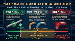
針對此矛盾,2026 年新版 ASME B31.1 確立了基於材料分級與「應變階梯(Strain Tiers)」的放寬機制3:Addressing this contradiction, the 2026 edition of ASME B31.1 established a relaxation mechanism based on material classification and “Strain Tiers”3:
- 低應變區(< 5%):多數材料可豁免後續熱處理程序。Low Strain Tier (< 5%): Most materials can be exempted from subsequent heat treatment procedures.
- 中應變區(5%~20%):此為 3D 與 5D 彎管的精確落點。新規範不再要求一刀切的熱處理,而是綜合考量材料類別、服役溫度、壁厚與 B31J 疲勞分析。對於普通碳鋼,若壁厚未超標且非強酸環境,工程師可依法放寬退應力熱處理;對於 P91 等高溫 CSEF 材料,規範雖強制要求熱處理,但允許採用精確控制的高週波感應加熱(IH-PBHT)技術3。此工法能完美重建回火馬氏體組織,確保高溫強度無損恢復。Medium Strain Tier (5%~20%): This is the precise range for 3D and 5D bends. The new code no longer demands one-size-fits-all heat treatments but comprehensively considers material classes, service temperatures, wall thickness, and B31J fatigue analysis. For standard carbon steels, if wall thickness limits are not exceeded and the environment is non-acidic, engineers can legally relax stress-relief heat treatment requirements. For high-temperature CSEF materials like P91, although heat treatment is mandatory, the code permits precisely controlled Induction Heating Post-Bend Heat Treatment (IH-PBHT)3. This technique perfectly rebuilds the tempered martensite microstructure, ensuring high-temperature strength is restored without loss.
- 高應變區(>20%):如5D 彎頭的強迫冷壓,因塑性耗竭嚴重,強制要求完全退火等最高等級熱處理。High Strain Tier (>20%): E.g., forced cold pressing of 1.5D elbows; due to severe plastic exhaustion, highest-grade heat treatments like full annealing are mandatorily required.
此階梯式放寬機制賦予了 3D/5D 冷作彎管在現代 CCPP 工程上的完全合法性與最佳化運作空間,使 IH-PBHT 應用更具科學依據,避免了整體熱處理帶來的材料降級與龐大成本。This tiered relaxation mechanism grants 3D/5D cold bends complete legitimacy and optimal operational space in modern CCPP engineering, providing a solid scientific basis for IH-PBHT application and avoiding material degradation and the massive costs associated with bulk furnace heat treatments.
五、 電銲銲道之不可抗拒裂紋與微觀冶金限制 / V. Irresistible Cracks of Weld Seams and Micro-Metallurgical Limitations
要深刻理解 3D/5D 冷作彎管的絕對優勢,必須切換至微觀層面,徹底剖析傳統 1.5D 銲接彎頭中,電銲銲道所衍生的「不可抗拒」冶金缺陷。無論自動化銲接工法如何精進,高溫熔融與劇烈冷卻的熱循環,不可避免地會在銲接熱影響區(HAZ)留下微觀定時炸彈1。以下詳述四大裂紋機制:To deeply understand the absolute advantages of 3D/5D cold bends, one must shift to the microscopic level to thoroughly dissect the “irresistible” metallurgical defects derived from the weld seams in traditional 1.5D welded elbows. Regardless of how advanced automated welding techniques become, the thermal cycles of high-temperature melting and severe cooling inevitably leave microscopic time bombs in the Heat-Affected Zone (HAZ)1. Four major cracking mechanisms are detailed below:
5.1 晶界液化開裂與 PMZ 脆化 / 5.1 Grain Boundary Liquation Cracking and PMZ Embrittlement
在銲縫邊緣的部分熔化區(PMZ),局部高溫會使金屬晶界處偏析的低熔點雜質優先液化19。當銲縫金屬凝固收縮時,處於半液態薄膜狀態的晶界會被應力無情拉裂,形成微觀的晶界液化裂紋。這些裂紋在初期難以透過常規非破壞檢測(NDT)察覺,但投入營運後會迅速擴展為貫穿管壁的疲勞裂紋。In the Partially Melted Zone (PMZ) at the edge of the weld seam, local high temperatures cause low-melting-point impurities segregated at the metal grain boundaries to preferentially liquefy19. When the weld metal solidifies and shrinks, the grain boundaries in a semi-liquid film state are mercilessly torn apart by stress, forming microscopic grain boundary liquation cracks. These cracks are difficult to detect via conventional Non-Destructive Testing (NDT) initially, but once in operation, they rapidly propagate into through-wall fatigue cracks.
5.2 高溫合金鋼的 Type IV 潛變破裂 / 5.2 Type IV Creep Rupture of High-Temperature Alloy Steels
對於 P91 等 CSEF 高強度合金鋼而言,Type IV 潛變破裂是最致命的失效模式1。銲接熱循環會導致細晶熱影響區發生不完全奧氏體化,使賦予 P91 高溫強度的奈米級碳氮化物析出相粗化或溶解。這種熱力學上的微觀軟化是不可逆的,高溫服役下的潛變空洞會隱匿且緩慢地在此成核。其最可怕之處在於「晚期突發性」,一旦跨過臨界點便會迅速匯聚成巨觀裂紋,導致管線在毫無預警下災難性斷裂1。For high-strength CSEF alloy steels like P91, Type IV creep rupture is the most fatal failure mode1. The welding thermal cycle causes incomplete austenitization in the fine-grained HAZ, leading to the coarsening or dissolution of nano-scale carbonitride precipitates that give P91 its high-temperature strength. This thermodynamic microscopic softening is irreversible, and creep voids nucleate covertly and slowly here under high-temperature service. The most terrifying aspect is its “late-stage suddenness”; once past a critical point, voids rapidly coalesce into macroscopic cracks, leading to catastrophic pipe failure without warning1.
5.3 應力鬆弛開裂與應變老化 / 5.3 Stress Relaxation Cracking and Strain Aging
應力鬆弛開裂常見於厚壁合金鋼銲道中。在未經充分熱處理的狀態下,銲道內部封存了極高額的拉伸殘餘應力。當材料試圖透過微觀局部塑性變形釋放應力時,若晶粒強度高於晶界,變形將被迫集中於薄弱的晶界處,導致沿晶開裂21。此外,HAZ 在經歷冷作變形與熱循環交替疊加後,極易發生應變老化,使斷裂韌性急遽下降17。Stress Relaxation Cracking (SRC) is common in thick-walled alloy steel welds. Without sufficient heat treatment, extremely high tensile residual stresses are locked inside the weld seam. When the material attempts to release these stresses through localized microscopic plastic deformation (creep), if grain strength is higher than grain boundary strength, deformation is forced to concentrate at the weak grain boundaries, resulting in intergranular cracking21. Furthermore, after undergoing alternating cycles of cold deformation and thermal cycling, the HAZ is highly susceptible to strain aging, causing a sharp drop in fracture toughness17.
5.4 銲道非金屬夾雜物與初始微裂紋網絡 / 5.4 Weld Seam Non-Metallic Inclusions and Initial Micro-Crack Networks
即便排除複雜的相變問題,厚壁管線銲縫內部仍難免殘留非金屬夾雜物(如氧化物、硫化物)18。這些夾雜物破壞了金屬基體的連續性,成為應力集中的微小尖端,在經歷初始疲勞加載時會率先萌生微裂紋。這些先天瑕疵決定了銲道永遠是管線系統中最脆弱的環節。Even setting aside complex phase-change issues, non-metallic inclusions (such as oxides and sulfides) inevitably remain inside thick-walled pipe welds18. These inclusions disrupt the continuity of the metal matrix, acting as tiny tips for stress concentration, and are the first to initiate micro-cracks under initial fatigue loading. These congenital flaws dictate that weld seams will always be the weakest link in the piping system.
六、 結構完整性評估:基於 BS 7910 與 API 579 的工程臨界評估 (ECA) / VI. Structural Integrity Assessment: Engineering Critical Assessment (ECA) Based on BS 7910 and API 579
為了將微觀冶金缺陷轉化為巨觀工程壽命預測,業界廣泛採用工程臨界評估(ECA)技術,其中以 BS 7910 與 API 579 最具權威性22。ECA 的核心工具是失效評估圖(FAD),其透過斷裂力學比(Kr)與塑性崩潰比(Lr)兩個無因次參數來界定缺陷的安全邊界15。To translate microscopic metallurgical defects into macroscopic engineering lifespan predictions, the industry widely adopts Engineering Critical Assessment (ECA) technologies, with BS 7910 and API 579 being the most authoritative22. The core tool of ECA is the Failure Assessment Diagram (FAD), which defines the safe boundary for defects using two dimensionless parameters: the fracture mechanics ratio (Kr) and the plastic collapse ratio (Lr)15.
6.1 銲接殘餘應力對 FAD 評估的致命打擊 / 6.1 The Fatal Blow of Weld Residual Stress on FAD Assessment
在 ECA 評估 1.5D 銲接彎頭時,會面臨致命的物理疊加效應:彎頭作為管線走向的轉折點,承受極高的宏觀系統位移應力(推升 Lr);同時,端部環向銲道蘊含逼近降伏極限的微觀殘餘應力並伴隨 HAZ 微裂紋(推升 Kr)15。這種「高位移應力」與「高殘餘應力」在物理空間上的絕對重疊,會直接將 FAD 評估點向右上方猛烈推移,輕易突破安全曲線進入失效區,使剩餘壽命預測極度不樂觀22。When evaluating 1.5D welded elbows via ECA, a fatal physical superposition effect is encountered: as the turning point of the pipe routing, the elbow endures extremely high macroscopic system displacement stresses (driving up Lr); concurrently, the end girth weld harbors microscopic residual stresses approaching the yield limit alongside HAZ micro-cracks (driving up Kr)15. This absolute physical overlap of “high displacement stress” and “high residual stress” violently pushes the FAD assessment point towards the upper right, easily breaching the safety curve into the failure zone, rendering remaining life predictions extremely pessimistic22.
6.2 冷作彎管在 ECA 框架下的空間解套策略 / 6.2 Spatial Resolution Strategy of Cold Bends Under the ECA Framework
理解 FAD 的殘酷現實後,3D/5D 冷作彎管的戰略價值便豁然開朗。透過採用一體成型的大半徑冷彎,工程師執行了物理空間上的「缺陷隔離」:原本位於高應力集中點的銲接接頭,被遠遠推移至低應力的平直管段上。宏觀一次與二次應力(Lr 貢獻值)因此巨幅削減,喪失外部彎矩驅動力後,裂紋尖端總體應力強度因子大幅下降,評估點成功拉回 FAD 安全區內。這種從根源消除應力疊加的佈局策略,遠比事後的非破壞檢測來得可靠。Understanding the harsh reality of FAD reveals the strategic value of 3D/5D cold bends. By adopting seamlessly formed large-radius cold bends, engineers execute physical “defect isolation”: the welded joint, originally located at a high-stress concentration point, is pushed far away onto the low-stress straight pipe section. Consequently, macroscopic primary and secondary stresses (contributing to Lr) are drastically reduced. Without the driving force of external bending moments, the overall stress intensification factor at the crack tip drops significantly, successfully pulling the assessment point back into the FAD safe zone. This layout strategy of eliminating stress superposition at the source is vastly more reliable than retrospective non-destructive testing.
七、 3D/5D 冷作彎管之流體動力學與 CCPP 全適用性深度評估 / VII. In-depth Evaluation of Fluid Dynamics and CCPP Full Applicability of 3D/5D Cold Bends
現代 CCPP 面臨極度頻繁的啟停操作,使 1.5D 銲接彎頭的應力集中與劣化問題指數級放大。導入 ASME B31.1 與 B31J 認可的 3D/5D 冷作彎管技術,不僅在固體力學層面具備優勢,更在流體動力學與經濟排程上展現壓倒性競爭力。Modern CCPPs face highly frequent start-stop operations, exponentially amplifying the stress concentration and degradation issues of 1.5D welded elbows. Introducing 3D/5D cold bending technology, endorsed by ASME B31.1 and B31J, provides not only solid mechanics advantages but also overwhelming competitiveness in fluid dynamics and economic scheduling.
7.1 流體動力學最佳化與流體加速腐蝕(FAC)的絕對抑制 / 7.1 Fluid Dynamics Optimization and Absolute Suppression of Flow-Accelerated Corrosion (FAC)
當高溫高壓蒸汽以極高流速通過 1.5D 短半徑彎頭時,劇烈流向改變會引發邊界層分離與強烈二次渦流。5D 彎管具備平滑綿長的過渡曲率,能有效抑制亂流生成,減少約 20% 至 30% 的流體壓力降,顯著提升整廠發電熱效率。更重要的是,平順的層流化流場巨幅降低了流體對內壁的動態剪應力,避免了磁鐵礦保護層的剝離,從物理機制上徹底消除了致命的流體加速腐蝕(FAC)熱點。When high-temperature, high-pressure steam passes through a 1.5D short-radius elbow at extremely high velocity, violent directional changes trigger boundary layer separation and intense secondary vortices. 5D bends possess a smooth, elongated transition curvature that effectively suppresses turbulence generation, reducing fluid pressure drops by roughly 20% to 30%, significantly improving overall plant thermal efficiency. More importantly, the smooth, laminarized flow field massively reduces dynamic shear stress against the inner wall, preventing the stripping of the protective magnetite layer, thereby completely eliminating fatal Flow-Accelerated Corrosion (FAC) hot spots from a physical mechanism standpoint.
7.2 精準微觀組織復原的 IH-PBHT 策略 / 7.2 Precision Microstructure Restoration Strategy via IH-PBHT
針對 P91 等高溫 CSEF 材料,傳統爐內 PWHT 往往受限於空間且可能加劇 HAZ 熱軟化。相反地,5D 彎管本體毫無銲道,工程師可透過高週波感應加熱(IH-PBHT)技術,對歷經塑性變形的彎管區段實施精確控溫的「正火 + 回火」程序。此打掉重練的微觀過程重新溶解了糾結的差排,並使強化相均勻細小地重新析出,使 5D 彎管完全恢復甚至超越母材級的高溫潛變抗力與衝擊韌性。For high-temperature CSEF materials like P91, traditional furnace PWHT is often constrained by space and can exacerbate HAZ thermal softening. Conversely, since the body of a 5D bend contains no welds, engineers can use Induction Heating Post-Bend Heat Treatment (IH-PBHT) technology to apply a precisely temperature-controlled “normalize + temper” procedure on the plastically deformed bend section. This microscopic “tear down and rebuild” process redissolves tangled dislocations and causes strengthening phases to reprecipitate evenly and finely, allowing the 5D bend to fully recover or even surpass base-metal levels of high-temperature creep resistance and impact toughness.
7.3 排程加速與經濟效益(以彎代銲工法) / 7.3 Schedule Acceleration and Economic Benefits (Bending instead of Welding)
在 2026 年全面強制的 B31J 矩陣下,執意使用 1.5D 銲接彎頭將無可避免遭遇應力超標困境,並衍生龐大的支吊架與減震器改造成本5。直接採用 SIF 趨近於 1.0 的 3D/5D 冷作彎管能從源頭將系統「柔性化」5。「以彎代銲」工法大幅減少了現場的環向銲接口數量,免除了大量銲前預熱、耗時的 PWHT 及昂貴的非破壞檢測(NDE)風險2。將管線在工廠內預製冷彎成三維模組,不僅能確保品質,更大幅加速了 CCPP 的建廠排程並降低總成本。Under the fully mandated 2026 B31J matrix, insisting on 1.5D welded elbows will inevitably lead to stress over-limit dilemmas, incurring massive retrofit costs for spring hangers and snubbers5. Directly adopting 3D/5D cold bends with SIFs approaching 1.0 inherently “flexibilizes” the system at the source5. The “bending instead of welding” methodology drastically reduces the number of onsite girth welds, eliminating the need for extensive preheating, time-consuming PWHT, and the risks of expensive NDE2. Prefabricating pipe into 3D modules via cold bending in the shop not only ensures quality but also significantly accelerates CCPP construction schedules and lowers total costs.
八、 多維度實務視角與利害關係人決策分析 / VIII. Multi-dimensional Practical Perspectives and Stakeholder Decision Analysis
高能管線的決策牽涉設計、營運與製造等多方視角。針對 3D/5D 冷作彎管的導入,各利害關係人在實務上有其獨特的考量與因應策略。High-energy piping decisions involve multiple perspectives spanning design, operations, and manufacturing. Regarding the introduction of 3D/5D cold bends, various stakeholders hold unique practical considerations and response strategies.
8.1 業主對於維護管理及營運之決策 / 8.1 Owner’s Decisions on Maintenance Management and Operations
對 CCPP 業主而言,管線可靠性直接關乎營收與工安。過去經驗表明,高階合金鋼的銲道往往在服役後期(超過 150,000 小時)才會爆發 Type IV 潛變裂紋,引發「未漏先破」災難。因此,業主在決策上日益傾向要求在設計階段即以大半徑冷作彎管取代銲接彎頭。此策略能巨幅降低每次歲修的檢測成本與排程壓力,具備高度的經濟效益與風險豁免價值。For CCPP owners, piping reliability directly correlates with revenue and industrial safety. Past experiences show that high-grade alloy steel welds typically erupt with Type IV creep cracks only late in service (exceeding 150,000 hours), causing “break-before-leak” disasters. Therefore, in their decision-making, owners increasingly demand the substitution of welded elbows with large-radius cold bends right at the design stage. This strategy massively reduces inspection costs and scheduling pressure during each annual turnaround, offering high economic benefits and risk exemption value.
8.2 EPC 承包商設計單位之空間排列與實務考量 / 8.2 EPC Contractor Design Unit’s Spatial Arrangement and Practical Considerations
從 EPC 設計單位視角出發,導入新版 B31J 規範帶來了設計挑戰10。由於 1.5D 彎頭 SIF 值居高不下,工程師必須在有限廠房內解決應力超標。採用 5D 冷作彎管成為最佳解方,其不僅能以超低 SIF 值平順轉移應力,且僅需 8% 的壁厚補償極限值,不會衍生訂製極端厚壁管材的困擾。透過三維佈局精算,設計單位能在不擴增佔地面積的前提下,順利通過 B31.1 的嚴苛檢核。From the perspective of an EPC design unit, introducing the new B31J code poses design challenges10. Because 1.5D elbows maintain high SIF values, engineers must resolve stress over-limits within confined plant spaces. Adopting 5D cold bends becomes the optimal solution; not only do they smoothly transfer stress with ultra-low SIF values, but they also require a mere 8% wall thickness compensation limit, avoiding the hassle of ordering extreme thick-walled pipes. Through precise 3D layout calculations, design units can successfully pass B31.1’s stringent checks without expanding the footprint.
8.3 廠務管理者對管線維護之要求 / 8.3 Plant Manager’s Requirements for Piping Maintenance
廠務管理者的首要任務是維持機組穩定。在日常維護中,FAC 是造成管線爆管的元凶,且傳統銲道需頻繁追蹤潛變老化。導入 3D/5D 冷作彎管後,層流場從物理上消滅了 FAC 熱點,免去針對彎管頻繁執行的超音波測厚追蹤。同時,去除高應力區銲道後,機組在經歷頻繁起停時不再擔憂 HAZ 微裂紋擴展,大幅提升調峰運轉的安全感。The primary task of a plant manager is to maintain unit stability. In daily maintenance, FAC is a primary culprit for pipe explosions, and traditional welds require frequent tracking for creep aging. After introducing 3D/5D cold bends, the laminar flow field physically eliminates FAC hot spots, negating the need for frequent ultrasonic thickness tracking on bends. Simultaneously, by removing welds from high-stress areas, there is no longer a fear of HAZ micro-crack propagation during frequent start-stops, vastly improving peace of mind during peak-shaving operations.
8.4 施作協力廠商之製造要求與因應策略 / 8.4 Manufacturing Requirements and Response Strategies of Subcontractors
冷作彎管協力廠商面臨著最嚴格的工法限制。在應對高應變率與高階合金鋼時,必須確保彎管截面扁平率嚴格控制在極限值內(如 8%以內);若減薄超過 5%,則需實施 100% 超音波測厚。針對 PBHT,廠商必須精準執行 IH-PBHT 工法,並於熱處理後執行硬度測試、表面非破壞性檢測與噴砂工序,防止氧化皮損壞下游精密葉片。Cold bending subcontractors face the strictest procedural limitations. When dealing with high strain rates and high-grade alloy steels, they must strictly control cross-sectional ovality within limits (e.g., under 8%); if thinning exceeds 5%, 100% ultrasonic thickness testing must be executed. For PBHT, manufacturers must precisely perform IH-PBHT techniques, and follow up with hardness testing, surface NDT, and sandblasting to prevent oxide scales from damaging delicate downstream turbine blades.
8.5 導入潁璋工程「能彎不銲」之三合一工法管理核心價值優化 / 8.5 Management Core Value Optimization of Ying Zhang Engineering’s “Bend, Don’t Weld” 3-in-1 Process
在實務施作層面,台灣業界指標性的潁璋工程所推行的「三合一工法」,在應對 2026 ASME 規範時展現了卓越的管理價值與技術前瞻性,並引起 EPC 統包商高度重視28。針對厚壁高強度合金,該工法首先運用高精度 CNC 數控冷作彎管機確保幾何成型精準度29,隨後結合精密的 IH-PBHT 數位化溫控恢復材料潛變抗力。其推廣的「能彎不銲」帶來四項顯著優化:徹底消除銲接熱應力與 HAZ 劣化、優化流體動力學降低 FAC 風險、直接豁免高昂的銲道 RT 檢測費用,並在缺工環境下大幅減少銲工人力需求,加速建廠排程。On the practical execution front, the “3-in-1 Process” promoted by Taiwan’s industry-leading Ying Zhang Engineering showcases exceptional management value and technical foresight in responding to the 2026 ASME codes, attracting high attention from EPC contractors28. For thick-walled high-strength alloys, the process first utilizes high-precision CNC cold bending machines to guarantee geometric forming accuracy29, and then integrates precise IH-PBHT with digital temperature control to restore the material’s creep resistance. Its promoted “bend, don’t weld” philosophy yields four notable optimizations: completely eliminating welding thermal stress and HAZ degradation; optimizing fluid dynamics to lower FAC risks; outright bypassing costly weld seam RT inspection fees; and drastically reducing welder manpower needs amidst labor shortages, accelerating plant construction schedules.
8.6 從發電機組設計製造商 (OEM) 視角看冷作彎管設計理念 / 8.6 The Cold Bending Design Philosophy from the Perspective of Power Generation OEMs
現代 CCPP 的核心動力源自大型燃氣渦輪機,而 GE、三菱電力與西門子等全球 OEM 大廠正不斷將效能推向極限(如三菱機組達成 1,600°C 渦輪入口溫度,並開發綠氫混燒技術)30。在極端高溫與氫氣介質環境中,OEM 對高能管線的「高可靠性」與「低維護需求」提出了前所未有的標準31。The core power of modern CCPPs stems from large gas turbines, and global OEM giants like GE, Mitsubishi Power, and Siemens are constantly pushing performance to the limits (e.g., Mitsubishi achieving 1,600°C turbine inlet temperatures and developing green hydrogen co-firing tech)30. In extreme high-temperature and hydrogen-medium environments, OEMs impose unprecedented standards on HEP for “high reliability” and “low maintenance requirements”31.
為落實「以彎代銲」理念,西門子等大廠在設計端開發了如 Solid Edge Piping Design 等先進 3D 軟體32,工程師能直接以自動生成管線路徑的方式繪製連續彎管系統,並透過專用彎管機無人工干預地精準成形33。對 OEM 大廠而言,減少銲接節點等同於消除疲勞斷裂點與氫脆化熱點。將冷作彎管導入模組化設計,確保了管線壽命與燃氣主機相匹配,並大幅簡化電廠未來的檢修動線,此為全球頂尖發電設備商推動管線工程變革的最核心理念。To implement the “bending instead of welding” philosophy, giants like Siemens have developed advanced 3D software such as Solid Edge Piping Design at the engineering front32. Engineers can directly draw continuous bent pipe systems via automated piping route generation, achieving precise forming without human intervention via dedicated pipe bending machines33. For large OEMs, reducing weld nodes equates to eliminating fatigue fracture points and hydrogen embrittlement hot spots. Incorporating cold bends into modular design ensures piping lifespan matches that of the gas turbine hosts and greatly simplifies future maintenance pathways, standing as the core ideology behind top global power equipment manufacturers driving piping engineering transformation.
九、 結論 / IX. Conclusion
ASME B31.1 與 B31J 規範在 2026 年版的聯合演進,標誌著全球高能管線工程從粗放的「經驗主義」正式邁向「精密微觀冶金與宏觀彈塑性力學深度結合」的歷史性轉折。B31J 空間方向性應力矩陣的全面強制化,宣告了傳統 Markl 疲勞理論與附錄 D 的終結,並毫不留情地揭露了 1.5D 短半徑銲接彎頭在高溫、高壓、大口徑與複雜三維應力下不容忽視的結構脆弱性。同時,電銲銲道固有的 Type IV 潛變破裂、晶界液化開裂等不可抗拒的冶金缺陷,在當今 CCPP 頻繁調峰的熱機械疲勞環境下,已成為隨時可能引發災難的定時炸彈。The joint evolution of the 2026 editions of the ASME B31.1 and B31J codes marks a historic turning point for global high-energy piping engineering, officially moving from crude “empiricism” to a “deep integration of precision micro-metallurgy and macro-elasto-plastic mechanics.” The mandatory implementation of B31J’s spatial directional stress matrix spells the end of traditional Markl fatigue theory and Appendix D, ruthlessly exposing the structural vulnerabilities of 1.5D short-radius welded elbows under high-temperature, high-pressure, large-diameter, and complex 3D stress conditions that can no longer be ignored. Meanwhile, irresistible metallurgical defects inherent in weld seams—such as Type IV creep rupture and grain boundary liquation cracking—have become ticking time bombs prone to trigger disasters at any moment in today’s thermo-mechanical fatigue environments of CCPP peak shaving.
透過深度解析 B31.1 新規範中對 5% ~ 20% 冷作彎曲應變率的階梯式彈性放寬與熱處理分級機制,本研究明確證實了 3D/5D 大半徑冷作彎管在現代工程學理上的完美契合度與不可替代性。5D 冷作彎管不僅精準落入規範的放寬區間,更憑藉逼近 1.0 的應力強度因子、極低的流體壓力降及優異的抗 FAC 特性,展現出壓倒性的優勢。最為關鍵的是,「以彎代銲」的物理佈局策略在工程臨界評估(ECA)的失效評估圖上實現了應力去耦合,徹底移除了高應力區的銲接弱點;再輔以精密的感應加熱彎後熱處理(IH-PBHT)技術,根絕了潛變與應力鬆弛開裂的發生要件。Through an in-depth analysis of the new B31.1 code’s tiered flexible relaxation and heat treatment grading mechanisms for cold bending strain rates between 5% and 20%, this study clearly verifies the perfect theoretical fit and irreplaceability of 3D/5D large-radius cold bends in modern engineering. 5D cold bends not only fall precisely into the code’s relaxation range but also demonstrate overwhelming advantages via SIFs approaching 1.0, extremely low fluid pressure drops, and exceptional anti-FAC properties. Most crucially, the physical layout strategy of “bending instead of welding” achieves stress decoupling on the Failure Assessment Diagram (FAD) of Engineering Critical Assessments (ECA), thoroughly removing welding weak points from high-stress zones. Supported by precise Induction Heating Post-Bend Heat Treatment (IH-PBHT) technology, it eradicates the prerequisites for creep and stress relaxation cracking.
結合潁璋工程等施作端的三合一工法,以及 GE、西門子等 OEM 大廠在 3D 自動化設計上的推波助瀾,3D/5D 冷作彎管早已超越單純管件替代品的範疇。在 2026 年嚴苛的新規範框架與能源轉型需求下,它已成為確保下一代複循環發電廠在極端調峰運轉條件下,達成結構完整性最佳化、生命週期最大化與最高營運安全標準的終極工程解方。Combined with the execution-side “3-in-1” methodology by firms like Ying Zhang Engineering, and the momentum from OEM giants like GE and Siemens driving automated 3D design, 3D/5D cold bends have long transcended the realm of mere pipe fitting substitutes. Under the rigorous 2026 code framework and energy transition demands, they have emerged as the ultimate engineering solution to ensure that next-generation combined cycle power plants achieve optimized structural integrity, maximized lifecycles, and the highest operational safety standards under extreme peak-shaving conditions.
參考文獻
- Review of Type IV Cracking in Piping Welds – EPRI, https://restservice.epri.com/publicdownload/TR-108971/0/Product
- https://yz-pipe-bending.com.tw/news/
- 2026 ASME 規範下1 動力管線施工工法之深度剖析, https://yz-pipe-bending.com.tw/2026-asme-%E8%A6%8F%E7%AF%84%E4%B8%8B-b31-1-%E5%8B%95%E5%8A%9B%E7%AE%A1%E7%B7%9A%E6%96%BD%E5%B7%A5%E5%B7%A5%E6%B3%95%E4%B9%8B%E6%B7%B1%E5%BA%A6%E5%89%96%E6%9E%90%EF%BC%9A5d-%E5%86%B7%E4%BD%9C%E5%BD%8E/
- ASME B31.1-2024 Stress Intensification Factors (SIFs) — FAQ, https://pipingtoolset.com/faq/b311-stress-intensification-factors/
- 複循環發電廠脫硝與碳捕捉管線系統採用3D/5D 冷作彎管工法取代, https://yz-pipe-bending.com.tw/%E8%A4%87%E5%BE%AA%E7%92%B0%E7%99%BC%E9%9B%BB%E5%BB%A0%E8%84%AB%E7%A1%9D%E8%88%87%E7%A2%B3%E6%8D%95%E6%8D%89%E7%AE%A1%E7%B7%9A%E7%B3%BB%E7%B5%B1%E6%8E%A1%E7%94%A8-3d-5d-%E5%86%B7%E4%BD%9C%E5%BD%8E/
- ASME B31.1-2016 – Standards Michigan, https://standardsmichigan.com/wp-content/uploads/2018/01/Proposed-Revision-of-B31.X-Power-Piping-Public-Review-Draft-2346.pdf
- ASME B31.1 與ASME B31.3 感應熱彎退應力熱處理(SRHT)差異化, https://yz-pipe-bending.com.tw/asme-b31-1-%E8%88%87-asme-b31-3-%E6%84%9F%E6%87%89%E7%86%B1%E5%BD%8E%E5%BE%8C%E9%80%80%E6%87%89%E5%8A%9B%E7%86%B1%E8%99%95%E7%90%86srht%E5%B7%AE%E7%95%B0%E5%8C%96%E5%88%86%E6%9E%90%E7%A0%94%E7%A9%B6/
- https://yz-pipe-bending.com.tw/asme-b31-1-%E8%88%87-b31-3-%E8%A6%8F%E7%AF%84%E4%B8%8B%E8%A8%AD%E8%A8%88%E5%BC%B7%E5%BA%A6%E8%88%87%E5%AE%89%E5%85%A8%E8%A3%95%E5%BA%A6%E5%B7%AE%E7%95%B0%EF%BC%9A2024-2026-%E5%B9%B4%E7%89%88-b31j/
- Fatigue Design of Process Equipment – Pressure Vessel Engineering, https://www.pveng.com/wp-content/uploads/2016/06/hinnant_asme_plant_engineering_presentation.pdf
- SIF & Flexibility Factors — ASME B31J-2023 & NM.1 HDPE, https://pipingtoolset.com/tools/sif-flexibility-factors/
- ASME B31J (2023) Stress Intensification Factors, https://docs.bentley.com/LiveContent/web/AutoPIPE-v2026/Help/en/Topics/Codes/ASME_B31J_2023_Stress_Intensification_Factors.html
- Mastering ASME B31J Piping Stress Analysis for Plant Integrity, https://epcland.com/asme-b31j-piping-stress-analysis/
- ASME B31.1 Power Piping 2018 Changes – Bradley Sawler, https://www.bradleysawler.com/engineering/asme-b31-1-power-piping-2018-changes/
- ASME B31.3 Process Piping – AquaEnergy Expo Knowledge Hub, https://kh.aquaenergyexpo.com/wp-content/uploads/2025/02/ASME-B31.3-Process-Piping.pdf
- (PDF) Spiral welded tubes – imperfections, residual stresses, and, https://www.researchgate.net/publication/280687231_Spiral_welded_tubes_-_imperfections_residual_stresses_and_buckling_characteristics
- Power Piping ASME Code for Pressure Piping, B31 – Wermac.org, https://www.wermac.org/pdf/asme_b31.1.pdf
- Jung-Chul (Thomas) Eun, https://mahcopipe.com/wp-content/uploads/2024/04/Handbook-of-Engineering-Practice-of-Materials-and-Corrosion.pdf
- Characterisation of weldment hardness, impact energy and, https://www.researchgate.net/publication/262568168_Characterisation_of_weldment_hardness_impact_energy_and_microstructure_in_API_X65_steel
- weld solidification cracking: Topics by Science.gov, https://www.science.gov/topicpages/w/weld+solidification+cracking
- 基於2025/2026 ASME B31.1 與B31J 最新規範複循環機組動力管線冷, https://yz-pipe-bending.com.tw/%E5%9F%BA%E6%96%BC-2025-2026-asme-b31-1-%E8%88%87-b31j-%E6%9C%80%E6%96%B0%E8%A6%8F%E7%AF%84%E8%A4%87%E5%BE%AA%E7%92%B0%E6%A9%9F%E7%B5%84%E5%8B%95%E5%8A%9B%E7%AE%A1%E7%B7%9A%E5%86%B7%E4%BD%9C%E5%BD%8E/
- Assessment of stress relaxation cracking of austenitic components in, https://www.nrc.gov/docs/ML2432/ML24323A060.pdf
- Verification of the Applicability of the FAD Method Based on Full, https://www.mdpi.com/1996-1944/19/3/465
- Engineering Critical Analyses to BS 7910 – TWI, https://www.twi-global.com/technical-knowledge/published-papers/engineering-critical-analyses-to-bs-7910-the-uk-guide-on-methods-for-assessing-the-acceptability-of-flaws-in-metallic-structures
- WELD RESIDUAL STRESS PROFILES FOR STRUCTURAL, https://oro.open.ac.uk/61280/1/13834721.pdf
- GL Noble Denton report template – ROSA P, https://rosap.ntl.bts.gov/view/dot/34644/dot_34644_DS1.pdf
- Tensile Strain Limit Design for Pipelines | PDF – Scribd, https://www.scribd.com/document/699497407/Validation-and-Documentation-of-Tensile-Strain-Limit-Design-Models-for-Pipelines
- ASME B31J: I & K Factors in Pipe Analysis, https://www.cortexsoftware.com.au/blog/understanding-asme-b31j-methods-i-factors-and-k-factors-in-piping-stress-analysis
- 彎管配管當所有路徑轉折點,都沒有經過焊接工序處理… 思考: 1.無, https://www.facebook.com/100057434619150/photos/%E5%BD%8E%E7%AE%A1%E9%85%8D%E7%AE%A1%E7%95%B6%E6%89%80%E6%9C%89%E8%B7%AF%E5%BE%91%E8%BD%89%E6%8A%98%E9%BB%9E%E9%83%BD%E6%B2%92%E6%9C%89%E7%B6%93%E9%81%8E%E7%84%8A%E6%8E%A5%E5%B7%A5%E5%BA%8F%E8%99%95%E7%90%86%E6%80%9D%E8%80%831%E7%84%A1%E7%84%8A%E6%8E%A5%E9%81%8E%E5%BE%8C%E7%9A%84%E7%86%B1%E6%87%89%E5%8A%9B%E5%BD%B1%E9%9F%BF2%E7%84%A1%E9%8A%B2%E9%81%93%E6%89%80%E5%BC%95%E8%B5%B7%E7%9A%84%E9%98%BB%E6%8A%97%E6%95%88%E6%87%893%E7%84%A1%E9%9C%80%E9%A1%8D%E5%A4%96%E6%94%AF%E4%BB%98%E9%8A%B2%E9%81%93x-ray%E9%9D%9E%E7%A0%B4%E5%A3%9E%E6%AA%A2%E6%B8%AC%E8%B2%BB%E7%94%A84%E6%B8%9B%E5%B0%91%E9%85%8D%E7%AE%A1%E5%B7%A5%E4%BA%BA%E6%95%B85%E6%B8%9B/291812659409886/
- 複循環電廠高能管線「彎管工法」整合研究:聲學共振抑制, https://yz-pipe-bending.com.tw/%E8%A4%87%E5%BE%AA%E7%92%B0%E9%9B%BB%E5%BB%A0%E9%AB%98%E8%83%BD%E7%AE%A1%E7%B7%9A%E3%80%8C%E5%BD%8E%E7%AE%A1%E5%B7%A5%E6%B3%95%E3%80%8D%E6%95%B4%E5%90%88%E7%A0%94%E7%A9%B6%EF%BC%9A%E8%81%B2%E5%AD%B8/
- Hydrogen-Ready Gas Turbines: 2026 OEM Comparison, https://www.greengasturbines.com/blog/hydrogen-ready-gas-turbines-oem-comparison
- Gas Turbines Review: Siemens, GE, Ansaldo and Mitsubishi, https://www.araner.com/blog/gas-turbines-review-siemens-ge-ansaldo-and-mitsubishi
- Solid Edge Piping Design – Siemens Digital Industries Software Blogs, https://blogs.sw.siemens.com/wp-content/uploads/sites/8/2024/10/Siemens-SW-Solid-Edge-Piping-Design-fs-75509-D15.pdf
- Pipe Bending Machine – ID: 109991081 – Industry Support Siemens, https://support.industry.siemens.com/cs/document/109991081/pipe-bending-machine?dti=0&dl=en&lc=zh-WW