
一、 緒論 / Chapter 1: Introduction
在現代燃氣複循環發電廠(Combined Cycle Power Plant, CCPP)與超臨界火力發電廠的設計與營運中,主蒸汽(Main Steam)與熱再熱蒸汽(Hot Reheat Steam)管線系統扮演著將極端熱能從熱回收鍋爐(HRSG)傳輸至汽輪機(Steam Turbine)的核心關鍵角色。這些高壓蒸汽管線長期運行於極端嚴苛的高溫(通常介於攝氏 570 度至 600 度之間)與高壓(170 bar 至 230 bar)環境下,因此工程界普遍採用具備優異高溫潛變抗性與抗氧化能力的高強度馬氏體合金鋼,如 ASTM A335 P91(簡稱 P91,屬於 9Cr-1Mo-V-Nb 級別鋼材)1。 In the design and operation of modern Combined Cycle Power Plants (CCPP) and supercritical thermal power plants, the Main Steam and Hot Reheat Steam piping systems play a critical role in transferring extreme thermal energy from the Heat Recovery Steam Generator (HRSG) to the Steam Turbine. Because these high-pressure steam lines operate continuously under severely high temperatures (typically between 570°C and 600°C) and pressures (170 bar to 230 bar), the engineering industry commonly utilizes high-strength martensitic alloy steels, such as ASTM A335 P91 (a 9Cr-1Mo-V-Nb grade steel), known for their excellent high-temperature creep resistance and oxidation resistance1.
高溫蒸汽在長距離傳輸的過程中,無可避免地會與管壁進行熱交換,並在系統啟動、停機或低負載運轉等瞬態操作期間產生冷凝水。若無法及時且有效地排除這些積水,流速極高的高速蒸汽便會夾帶冷凝水,對管線轉折處、閥門與支撐結構造成極具破壞性的水錘效應(Water Hammer)與熱分層(Thermal Stratification)現象2。為此,國際規範與美國電力研究所(EPRI)嚴格要求主蒸汽幹管必須具備連續且穩定的下傾洩水坡度(Drainage Slope),標準通常為百分之一,亦即每英呎長度需有八分之一英吋的下傾量(1:100),以此利用重力將冷凝水精確引導至疏水點2。 During long-distance transmission, high-temperature steam inevitably exchanges heat with the pipe walls, generating condensate during transient operations such as system startup, shutdown, or low-load running. If this accumulated water is not drained promptly and effectively, the high-velocity steam will carry the condensate, causing highly destructive water hammer and thermal stratification phenomena at piping bends, valves, and support structures2. To prevent this, international standards and the Electric Power Research Institute (EPRI) strictly require main steam headers to have a continuous and stable downward drainage slope, typically standardized at one percent (or a 1/8-inch drop per foot, i.e., 1:100), utilizing gravity to guide condensate accurately to the drain points2.
然而,由於管線必須穿梭於錯綜複雜的廠房鋼構與既有設備之間,這使得管線在三維空間的轉折角度極少為標準的四十五度或九十度,反而經常形成如四十四點三度、八十八點九度等非標準空間角7。為了適應這些非標準角度並維持精確的洩水坡度,工程實務上面臨管件工法選擇的兩難。傳統工法傾向將預製的標準 1.5D 鍛造對銲彎頭進行現場機械裁切,亦即所謂的斜切對銲(Trimmed Elbows 或 Miter Cuts),藉此破壞其原有的幾何連續性再進行拼接;相對地,現代化製程則推崇採用 3D 或 5D 數控一體成型冷作彎管(Cold Bending),以保持管件的幾何平順度與連續性2。 However, because piping must weave through intricate plant steel structures and existing equipment, three-dimensional directional changes rarely form standard 45-degree or 90-degree angles; instead, non-standard spatial angles like 44.3° or 88.9° frequently occur7. To accommodate these non-standard angles while maintaining precise drainage slopes, engineering practices face a dilemma in selecting piping methods. Traditional methods tend to mechanically cut prefabricated standard 1.5D forged butt-weld elbows on-site—known as trimmed elbows or miter cuts—thereby destroying their original geometric continuity for splicing. Conversely, modern manufacturing promotes the use of 3D or 5D CNC integrated cold bending to preserve the geometric smoothness and continuity of the fittings2.
本研究旨在深入探討 CCPP 高壓蒸汽管線洩水坡度設計理念與實際操作手法,並針對「現場斜切對銲彎頭」與「一體成型冷作彎管」兩種工法進行全面性的比較研究與可靠度分析。論述範疇涵蓋兩相流場擾動與流動加速腐蝕(FAC)評估、P91 鋼之冶金風險與第四型潛變(Type IV Creep)破裂機制、基於最新 ASME B31J 規範之應力與柔性解耦分析、先進相控陣列超音波檢測(PAUT)之技術挑戰,以及綜合全生命週期成本(Life Cycle Cost, LCC)之經濟效益。最終,本研究將結合台灣特有的管線工程實務經驗,總結出提升系統長期可靠度之最佳實踐方案。 This study aims to deeply explore the design philosophy and practical operations of drainage slopes in CCPP high-pressure steam lines, and conduct a comprehensive comparative study and reliability analysis between “on-site mitered/trimmed elbows” and “integrated cold bends.” The discussion encompasses evaluations of two-phase flow disturbances and Flow-Accelerated Corrosion (FAC), metallurgical risks of P91 steel and Type IV creep cracking mechanisms, stress and flexibility decoupling analysis based on the latest ASME B31J code, technological challenges of advanced Phased Array Ultrasonic Testing (PAUT), and the economic benefits regarding Life Cycle Cost (LCC). Ultimately, integrating Taiwan’s unique piping engineering practices, this study will summarize best practices for enhancing the long-term reliability of these systems.
二、 CCPP 高壓蒸汽管線洩水坡度設計理念與操作手法 / Chapter 2: Drainage Slope Design Philosophy and Operational Practices for CCPP High-Pressure Steam Lines
高壓蒸汽系統在啟動階段,管內不可避免地會產生大量冷凝水。因此,洩水坡度的設計必須與實際運轉操作手法緊密配合,這也是防止災難性熱應力破壞的基礎。在設計理念上,為了確保冷凝水能順暢且連續地流向疏水閥(Drain Valve),管線佈局必須嚴格避免任何微小的逆坡或水平段。若設計不當致使冷凝水在管底部積聚,當高達攝氏六百度的高溫蒸汽流經該管段時,管壁上下半部會產生巨大的垂直溫度梯度,導致管壁產生永久性的彎曲變形(Sagging)並誘發嚴重的熱疲勞裂紋。同時,積液若阻塞部分管截面,後方高速推進的蒸汽會瞬間捲起水柱(Slug),形成液態衝擊波,以極高動能轟擊下游的管件轉折處或設備,造成嚴重的次生水錘效應。 During the startup phase of high-pressure steam systems, the generation of massive amounts of condensate is unavoidable. Therefore, drainage slope design must be tightly coordinated with practical operational procedures, forming the foundation for preventing catastrophic thermal stress failures. Conceptually, to ensure that condensate flows smoothly and continuously toward drain valves, the piping layout must strictly avoid any minor adverse slopes or horizontal sections. If improper design allows condensate to pool at the bottom of the pipe, the passage of 600°C high-temperature steam will create a massive vertical temperature gradient between the upper and lower pipe walls, causing permanent sagging deformation and inducing severe thermal fatigue cracks. Simultaneously, if the accumulated liquid blocks part of the pipe’s cross-section, the high-speed advancing steam behind it will instantly sweep up a slug of water, forming a liquid shockwave that strikes downstream bends or equipment with immense kinetic energy, resulting in severe secondary water hammer effects.
在實際操作手法方面,CCPP 電廠的高壓蒸汽系統啟動(尤其是暖機啟動,Warm Light-Up)涉及一系列極為精密的熱力學控制程序。在鍋爐點火與暖機的初始階段,操作人員必須先建立冷凝器的高真空度(通常要求達到負零點九一的真空標準),以為後續的蒸汽流動與疏水創造負壓抽吸條件9。充壓主蒸汽(Main Steam, MS)管線前,需先開啟主蒸汽停汽閥(MS Stop Valve)的旁通閥進行管線暖機,同時微調節流啟動排氣閥(Startup Vent),並透過油壓控制燃燒率,使汽鼓金屬溫度的上升率嚴格控制在每小時攝氏一百一十度以內,以防熱應力過大。 In terms of operational practices, the startup of CCPP high-pressure steam systems (particularly the warm light-up) involves a series of highly precise thermodynamic control procedures. During the initial stages of boiler ignition and warm-up, operators must first establish a high vacuum in the condenser (typically requiring a standard of -0.91), creating negative pressure suction conditions for subsequent steam flow and drainage9. Before pressurizing the Main Steam (MS) lines, the bypass valve of the MS Stop Valve must be opened for pipe warm-up, while simultaneously throttling the startup vent and controlling the firing rate via oil pressure. This strictly limits the drum metal temperature rise rate to within 110°C per hour, preventing excessive thermal stress.
隨著熱回收鍋爐開始產汽,當蒸汽壓力與溫度達到特定門檻(如 8 kg/cm² 且攝氏一百六十至一百八十度)時,高壓與低壓旁通閥必須開啟,引導未達標準的蒸汽繞過汽輪機直接進入冷凝器。在此過程中,確保主蒸汽溫度高於汽輪機轉子軸溫度至少攝氏三十度是極為關鍵的控制指標。直至各項參數趨於穩定且滿足連鎖條件,主汽輪機停汽閥方可全開。在整個暖機與旁通操作的過程中,洩水坡度扮演了維持管線內部絕對無積水的物理保證,而管件的幾何平順度則直接決定了疏水過程是否順暢無阻。 As the Heat Recovery Steam Generator begins producing steam, and when steam pressure and temperature reach specific thresholds (e.g., 8 kg/cm² and 160°C–180°C), the high-pressure and low-pressure bypass valves must be opened. This routes sub-standard steam around the turbine directly into the condenser. Throughout this process, ensuring that the main steam temperature is at least 30°C higher than the turbine shaft temperature is a crucial control parameter. The main turbine stop valves can only be fully opened once all parameters stabilize and interlock conditions are met. Throughout the warm-up and bypass operations, the drainage slope acts as the physical guarantee for maintaining an absolutely water-free environment inside the piping, while the geometric smoothness of the fittings directly determines whether the drainage process is unimpeded.
2.1 偏門實務工法:「大小縫隙」強行組對之工程與法規危害 / 2.1 Unorthodox Field Practices: Engineering and Regulatory Hazards of Forced Fit-Up with Uneven Root Gaps
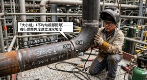
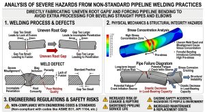
在現場施工中,若為避免斜切直管與彎頭帶來的額外加工與對心麻煩,部分施工單位會採取另一種非標準作法:即不對管件進行機械斜切,而是直接在標準對銲接口處刻意製造「大小縫」(即銲道根部間隙一側大、一側小),藉由強行扳折管線角度來建立所需的洩水坡度。然而,這種便宜行事的作法在工程法規與物理力學上將引發極嚴重的危害: In field construction, to avoid the extra machining and alignment hassles associated with trimming straight pipes and elbows, some construction units adopt another non-standard approach: instead of mechanically mitering the fittings, they intentionally create “uneven root gaps” (one side large, one side small) at standard butt-weld joints, forcefully bending the pipe angle to establish the required drainage slope. However, this cut-corner practice induces severe hazards in terms of engineering regulations and physical mechanics:
- 嚴重違反 ASME 規範之組對公差: 依據 ASME B31.1(動力管線)、B31.3(製程管線)以及 ASME B16.25 端部準備標準,管線對銲的根部間隙(Root Gap)必須嚴格符合已檢定之銲接程序規範(WPS),通常標準間隙要求為 1.6 mm ± 0.8 mm10。同時,法規嚴格限制單面銲接的內部錯位(Internal Misalignment)不得超過約 1.6 mm11。採用大小縫強行扳折組對,會導致極嚴重的內部錯位與間隙失真,完全超出法規允許的極限值。Severe Violation of ASME Fit-Up Tolerances: According to ASME B31.1 (Power Piping), B31.3 (Process Piping), and ASME B16.25 end preparation standards, the root gap of a butt weld must strictly comply with the qualified Welding Procedure Specification (WPS), typically requiring a standard gap of 1.6 mm ± 0.8 mm10. Concurrently, the code strictly limits internal misalignment for single-sided welding to no more than approximately 1.6 mm11. Forcing an angled fit-up using uneven gaps causes severe internal misalignment and gap distortion, completely exceeding the permissible code limits.
- 根部銲接缺陷與熱膨脹受阻: 在大小縫的極端組對狀態下,間隙過大的一側,銲縫間距會超出銲工能有效控制熔池的極限,極易導致根部銲穿(Burn-through)15;而間隙過小或密合的一側,則會阻礙管材在銲接熱循環過程中的熱膨脹空間,以致無法徹底銲透(Lack of Penetration),並極易在熱應力擠壓下誘發根部熱疲勞裂紋11。Root Weld Defects and Thermal Expansion Restriction: Under extreme uneven gap fit-ups, the spacing on the excessively wide side exceeds the welder’s limit to effectively control the weld pool, easily leading to root burn-through15. Conversely, the overly narrow or completely touching side restricts the material’s thermal expansion space during the welding thermal cycle, resulting in a lack of penetration and a high propensity for inducing root thermal fatigue cracks under thermal stress compression11.
- 殘餘應力集中與 P91 潛變加速: 為了維持大小縫的非自然角度,現場通常需要使用夾具強行固定後進行點銲。這種強加應力的行為會在銲縫處產生極大的殘餘張力集中11。對於 P91 這類對應力集中極度敏感的高階合金鋼而言,銲縫根部的幾何突變、缺口以及強大的殘餘應力將成為最完美的裂紋起始點,進而急遽加速第四型潛變破裂的發生。Residual Stress Concentration and Accelerated P91 Creep: To maintain the unnatural angle of the uneven gap, the site usually requires the use of clamps for forced fit-up before tack welding. This imposition of stress generates massive residual tensile stress concentrations at the weld11. For high-grade alloy steels like P91, which are extremely sensitive to stress concentrations, the geometric abruptions, notches, and immense residual stresses at the weld root become the perfect crack initiation sites, sharply accelerating the occurrence of Type IV creep cracking.
三、 兩相流場擾動與流動加速腐蝕(FAC)評估 / Chapter 3: Evaluation of Two-Phase Flow Disturbances and Flow-Accelerated Corrosion (FAC)
延續前章對於洩水幾何的探討,當高壓蒸汽夾帶部分冷凝水流經管線轉折處時,管件內部的幾何連續性對流體力學行為有著決定性的影響。將預製的 1.5D 鍛造彎頭進行現場斜切對銲所產生的流場擾動,遠比一般預期更為劇烈。計算流體力學(CFD)的模擬結果顯示,流動加速腐蝕(Flow-Accelerated Corrosion, FAC)是管線彎頭處最常見的失效模式之一,其嚴重程度與流場中的湍流強度、壁面剪應力(Wall Shear Stress)及流體速度分佈息息相關16。 Following the previous chapter’s discussion on drainage geometry, the geometric continuity inside the fittings has a decisive impact on fluid dynamics when high-pressure steam carrying partial condensate flows through piping bends. The flow disturbances generated by on-site miter welding of prefabricated 1.5D forged elbows are far more severe than generally expected. Computational Fluid Dynamics (CFD) simulation results show that Flow-Accelerated Corrosion (FAC) is one of the most common failure modes at piping elbows, with its severity closely related to turbulence intensity, wall shear stress, and fluid velocity distribution in the flow field16.
斜切彎頭內部形成的銳角與突變曲率,徹底破壞了流線的平順性。在雷諾數(Re)高達一百三十三萬至五百八十一萬的極高湍流狀態下,流體在彎頭內側(Intrados)會面臨極大的逆向壓力梯度(Adverse Pressure Gradient)。這種極端的壓力變化會導致邊界層發生嚴重剝離,剝離後的流體隨即在轉角內側形成巨大的分離泡(Separation Bubble)與低速回流區。與此同時,流體通過彎頭時,離心力促使橫截面上產生次級壓力梯度,驅使流體從內側向外側流動,形成雙股反向旋轉的二次流,即迪恩渦流(Dean Vortices)。斜切彎頭由於其有效彎曲半徑極小且伴隨幾何截斷,導致迪恩數顯著激增,使得湍流強度與壁面剪應力均達到極值2。 The sharp angles and abrupt curvature changes formed inside miter bends completely destroy the smoothness of the streamlines. Under extremely high turbulent conditions with Reynolds numbers (Re) reaching 1.33 million to 5.81 million, the fluid faces a massive adverse pressure gradient on the intrados of the bend. This extreme pressure change causes severe boundary layer separation, and the separated fluid subsequently forms a massive separation bubble and low-speed recirculation zone on the inside of the corner. Simultaneously, as the fluid passes through the bend, centrifugal force creates a secondary pressure gradient across the cross-section, driving the fluid from the inside toward the outside, forming dual counter-rotating secondary flows known as Dean vortices. Due to the extremely small effective bend radius and geometric truncation of miter bends, the Dean number surges significantly, driving turbulence intensity and wall shear stress to extreme peak values2.
這種強烈的擾流尾流結構不僅會延伸至彎頭下游數十倍管徑的距離,更會藉由極高的局部流速與湍流,不斷剝離並溶解管壁表面的保護性氧化層。特別是在溶氧量(Dissolved Oxygen, DO)波動的環境下,表面氧化層的破壞與生成機制失衡,將誘發並急遽加速流動加速腐蝕(FAC)與局部沖刷腐蝕(Erosion-Corrosion)的進程2。分離泡形成的低速停滯區使得蒸汽動能不足以懸浮微小的冷凝水滴,導致質量較大的液態水迅速沉降於斜切拼接處。若斜切角度的施工誤差產生了微小的逆坡,冷凝水便會在此大量積聚。再者,流體通過幾何銳角時,剪切層內部的局部靜壓會急遽下降,一旦低於飽和蒸汽壓便會產生局部閃蒸現象,形成高壓氣袋(Air Pockets)。在系統壓力瞬態波動時,這些氣袋會發生劇烈潰滅,產生類似空穴效應(Cavitation)的強大微射流,持續轟擊周遭的銲縫金屬。 This intense turbulent wake structure not only extends dozens of pipe diameters downstream of the bend, but also continually strips and dissolves the protective oxide layer on the pipe surface via extremely high localized flow velocities and turbulence. Especially in environments with fluctuating Dissolved Oxygen (DO) levels, the imbalance between the destruction and formation mechanisms of the surface oxide layer induces and sharply accelerates Flow-Accelerated Corrosion (FAC) and localized erosion-corrosion2. The low-speed stagnation zone created by the separation bubble leaves the steam with insufficient kinetic energy to suspend fine condensate droplets, causing the denser liquid water to rapidly settle at the miter splice. If construction errors in the miter angle create a slight adverse slope, condensate will pool heavily here. Furthermore, as fluid passes over the sharp geometric angles, local static pressure within the shear layer drops precipitously; once it falls below the saturated steam pressure, localized flashing occurs, forming high-pressure air pockets. During transient system pressure fluctuations, these air pockets collapse violently, producing powerful microjets akin to cavitation that continuously bombard the surrounding weld metal.
相較之下,採用現代 3D 或 5D 數控冷作技術彎製的鋼管,能夠在三維空間中精準達到任何非標準角度,同時維持管線完美的幾何連續性與平順曲率。大彎曲半徑顯著降低了離心力與橫向壓力梯度,有效抑制了邊界層剝離與迪恩渦流的生成。CFD 分析證實,一體成型平滑彎管的湍流強度遠低於斜切彎頭,這從根本上消除了 FAC 發生的高風險條件,並徹底排除了局部積液與氣袋潰滅的潛在威脅2。 In contrast, steel pipes bent using modern 3D or 5D CNC cold working technologies can accurately reach any non-standard angle in three-dimensional space while maintaining perfect geometric continuity and smooth curvature. The large bend radius significantly reduces centrifugal forces and lateral pressure gradients, effectively suppressing boundary layer separation and the generation of Dean vortices. CFD analysis confirms that the turbulence intensity in integrated smooth cold bends is far lower than that in miter bends, fundamentally eliminating the high-risk conditions for FAC and completely ruling out the potential threats of localized liquid accumulation and air pocket collapse2.
四、 P91 鋼之冶金風險與第四型潛變破裂(Type IV Cracking)分析 / Chapter 4: Metallurgical Risks of P91 Steel and Type IV Creep Cracking Analysis
流體力學的劇烈擾動進一步加劇了管材的物理負荷,而在微觀冶金層面,ASTM A335 P91 材料的穩定性更是決定系統長期可靠度的核心。P91 鋼作為一種高強度的馬氏體耐熱鋼,其卓越的高溫潛變強度與抗氧化能力,高度依賴於其經精密正規化(通常於攝氏 1040 至 1080 度進行)與高溫回火(通常於攝氏 730 至 800 度進行)熱處理所形塑的微觀組織。P91 的基體為回火麻田散鐵(Tempered Martensite),其強化機制主要來自兩個方面:其一,分佈於原奧斯田鐵晶界與馬氏體板條邊界上的富鉻 M23C6碳化物負責有效釘扎晶界;其二,均勻散佈於馬氏體板條內部的奈米級富釩及富鈮的 MX 型碳氮化物,能顯著阻礙差排(Dislocations)的運動1。 Intense fluid dynamic disturbances further exacerbate the physical load on the pipe material, while at the micro-metallurgical level, the stability of ASTM A335 P91 material is the core determinant of the system’s long-term reliability. As a high-strength martensitic heat-resistant steel, P91’s exceptional high-temperature creep strength and oxidation resistance rely heavily on its microstructure, which is shaped by precise normalizing (typically between 1040°C and 1080°C) and high-temperature tempering (typically between 730°C and 800°C). The matrix of P91 is tempered martensite, and its strengthening mechanisms derive mainly from two sources: first, chromium-rich M23C6 carbides distributed along prior austenite grain boundaries and martensite lath boundaries effectively pin the grain boundaries; second, nanoscale vanadium- and niobium-rich MX carbonitrides uniformly dispersed within the martensite laths significantly hinder the movement of dislocations1.
4.1 銲接熱循環與熱影響區(HAZ)的微觀退化機制 / 4.1 Welding Thermal Cycles and Microstructural Degradation Mechanisms in the Heat-Affected Zone (HAZ)
當 P91 鋼進行現場銲接時,銲縫兩側的母材會經歷極不均勻的高溫熱循環,形成微觀結構極度複雜且性質各異的熱影響區(Heat-Affected Zone, HAZ)。依據峰值溫度的差異,HAZ 可細分為粗晶區、細晶區(FGHAZ)與跨臨界區(ICHAZ)。其中,細晶熱影響區與跨臨界熱影響區的峰值溫度剛好介於相變下臨界溫度(Ac1)與上臨界溫度(Ac3)之間。在此極端溫度區間,鋼材基體發生不完全的奧斯田鐵相變,導致晶粒嚴重細化。更為致命的是,原本負責析出強化的沉澱物發生部分溶解或嚴重的粗化(Coarsening),徹底喪失了對晶界與差排的釘扎能力,從而在銲縫外圍形成了一道微觀結構極為脆弱的「軟化帶」2。 When P91 steel is welded on-site, the base metal on both sides of the weld experiences highly non-uniform high-temperature thermal cycles, forming a Heat-Affected Zone (HAZ) with extremely complex microstructures and varying properties. Based on peak temperature differences, the HAZ is subdivided into the coarse-grained, fine-grained (FGHAZ), and intercritical (ICHAZ) zones. The peak temperatures of the FGHAZ and ICHAZ fall exactly between the lower (Ac1) and upper (Ac3) critical transformation temperatures. In this extreme temperature range, the steel matrix undergoes incomplete austenite transformation, leading to severe grain refinement. More fatally, the precipitates originally responsible for strengthening undergo partial dissolution or severe coarsening, completely losing their ability to pin grain boundaries and dislocations, thereby forming an extremely fragile microstructural “softened zone” surrounding the weld2.
在 CCPP 頻繁啟停所帶來的高溫與熱膨脹交變應力下,系統整體的變形應力會高度集中於這道力學性能最弱的 HAZ 軟化帶。在長期的潛變過程中,微觀空孔(Creep Voids)會優先於析出的脆性 Laves 相與粗化的碳化物周圍形核、成長,並逐漸聚集成微裂紋。這些裂紋最終沿著細晶區的晶界迅速擴展,引發無預警的宏觀脆性斷裂,此即為業界聞之色變的第四型潛變破裂(Type IV Creep Failure)2。採用 1.5D 彎頭進行現場斜切與對銲,無異於在管線系統應力最集中、流場擾動最劇烈的幾何轉折處,人為地增加了極高風險的銲縫,將 Type IV 潛變破裂的風險推向極致。 Under the high temperatures and alternating thermal expansion stresses caused by frequent CCPP startups and shutdowns, the system’s overall deformation stress heavily concentrates in this weakest HAZ softened zone. During the long-term creep process, micro-voids (creep voids) preferentially nucleate and grow around precipitated brittle Laves phases and coarsened carbides, gradually coalescing into micro-cracks. These cracks eventually propagate rapidly along the grain boundaries of the FGHAZ, triggering unheralded macroscopic brittle fracture—known industrially as the dreaded Type IV Creep Failure2. Using 1.5D elbows for on-site miter welding is tantamount to artificially adding extremely high-risk welds at the very geometric turns where stress is most concentrated and flow disturbances are most severe, pushing the risk of Type IV creep cracking to its absolute limit.
4.2 銲後熱處理(PWHT)的極端挑戰與 Ac1 溫度抑制效應 / 4.2 Extreme Challenges in Post-Weld Heat Treatment (PWHT) and the Ac1 Temperature Suppression Effect
為恢復 HAZ 的韌性並釋放銲接殘餘應力,ASME 規範強制要求 P91 鋼在銲接後必須進行嚴格的銲後熱處理(PWHT)。然而,實務上 P91 的最佳 PWHT 溫度區間極為狹窄,必須精確控制於攝氏 730 度至 760 度之間28。若溫度過低,馬氏體回火不完全,極易引發氫致裂紋與應力腐蝕破裂;若溫度過高超過 Ac1,已回火的馬氏體將發生逆向相變(Re-austenitization),冷卻後形成脆性馬氏體,徹底摧毀潛變壽命。 To restore HAZ toughness and relieve residual welding stress, ASME codes mandate strict Post-Weld Heat Treatment (PWHT) for P91 steel after welding. However, in practice, the optimal PWHT temperature window for P91 is extremely narrow and must be precisely controlled between 730°C and 760°C28. If the temperature is too low, martensite tempering is incomplete, highly risking hydrogen-induced cracking and stress corrosion cracking; if the temperature is too high and exceeds Ac1, the tempered martensite will undergo re-austenitization, forming brittle untempered martensite upon cooling and completely destroying the creep life.
更具挑戰性的是,現代 P91 銲條通常會添加微量的鎳(Ni)與錳(Mn)元素以提升低溫韌性。研究表明,這些元素會顯著降低 Ac1 溫度。當 Ni+Mn 總含量達 1.2% 時,銲縫金屬的 Ac1 溫度可能會降至攝氏 792 度甚至更低28。這意味著現場 PWHT 的安全餘裕將被嚴重壓縮。 Even more challenging is that modern P91 welding consumables usually add trace amounts of Nickel (Ni) and Manganese (Mn) to improve low-temperature toughness. Research shows these elements significantly depress the Ac1 temperature. When the combined Ni+Mn content reaches 1.2%, the Ac1 temperature of the weld metal can drop to 792°C or even lower28. This means the safety margin for field PWHT is severely compressed.
此外,適當的保溫時間對減緩 Type IV 破裂至關重要,但若過度延長(如超過 15 小時),則會導致基體過度軟化與異常析出,大幅降低潛變壽命22。在現場針對斜切彎頭進行局部感應加熱時,複雜且不規則的幾何形狀使得加熱線圈與保溫層難以均勻包覆,極易造成管壁內外產生巨大的溫度梯度。在此情況下,要確保內壁達到 730 度的最低要求,外壁的局部熱點極可能超過 800 度,直接跨越了降低後的 Ac1 溫度界線30。相對而言,冷作彎管免除了轉折處的幾何複雜銲縫,僅需在直管段進行標準對銲,使 PWHT 的溫度均勻性與控制精度大幅提升。 Additionally, an appropriate holding time is crucial for mitigating Type IV cracking; however, excessively prolonging it (e.g., over 15 hours) causes severe matrix softening and abnormal precipitation, drastically reducing creep life22. During localized induction heating of miter bends in the field, the complex and irregular geometry makes uniform wrapping of heating coils and insulation blankets difficult, easily generating massive temperature gradients between the inner and outer pipe walls. Under these conditions, ensuring the inner wall reaches the minimum 730°C requirement makes it highly likely that localized hot spots on the outer wall will exceed 800°C, directly crossing the depressed Ac1 temperature boundary30. In contrast, cold bends eliminate geometrically complex welds at the turns, requiring only standard girth welds on straight sections, thereby drastically improving PWHT temperature uniformity and control precision.
五、 基於 ASME B31J 規範之管線應力與流體柔性分析 / Chapter 5: Piping Stress and Flexibility Analysis Based on ASME B31J Code
在理解了冶金風險與幾何流場的相互作用後,針對整個管線系統在熱膨脹及動態負載下的應力分佈分析顯得尤為重要。傳統的 ASME B31.1 與 B31.3 規範主要依賴其附錄 D 的經驗公式來計算應力強度因子(SIF)與柔性因子(k)。然而,這些奠基於 1950 年代測試的遺留公式存在過度保守的缺陷,且未能有效區分面內(In-plane)與面外(Out-of-plane)受力行為的差異2。 Having understood the interaction between metallurgical risks and geometric flow fields, analyzing the stress distribution of the entire piping system under thermal expansion and dynamic loads becomes particularly crucial. Traditional ASME B31.1 and B31.3 codes rely heavily on their Appendix D empirical formulas to calculate Stress Intensification Factors (SIF) and flexibility factors (k). However, these legacy formulas, based on tests from the 1950s, suffer from overly conservative flaws and fail to effectively distinguish between in-plane and out-of-plane loading behaviors2.
5.1 ASME B31J 規範之範式轉移與解耦機制 / 5.1 Paradigm Shift and Decoupling Mechanisms in ASME B31J Code
為解決上述技術瓶頸,2023 年版 ASME B31J 規範將應力分析推進至以高解析度有限元素分析(FEA)為基礎的精密時代13。其核心變革在於將評估疲勞裂紋萌生的「應力強度因子(SIF)」與評估抗塑性崩塌能力的「持續應力指數(SSI)」在物理機制上進行了徹底的解耦2。 To overcome these technical bottlenecks, the 2023 edition of the ASME B31J code propels piping stress analysis into an era of precision based on high-resolution Finite Element Analysis (FEA)13. Its core paradigm shift lies in thoroughly decoupling the physical mechanisms between the “Stress Intensification Factor (SIF)”—used to evaluate fatigue crack initiation—and the “Sustained Stress Index (SSI),” which evaluates the resistance to plastic collapse2.
B31J 摒棄了單一 SIF 概念,分別定義了面內 SIF、面外 SIF 與扭轉 SIF,使分析軟體能真實反映不同方向彎矩的應力集中行為14。其次,針對持續負載,B31J 明確規定 SSI 取值為0.75i(最低不小於 1.0)。這排除了過往法規中不合理的過度保守設計,使得評估高壓管線在極端高溫下的潛變壽命更為精準2。 B31J abandons the concept of a single SIF, defining instead separate in-plane SIF, out-of-plane SIF, and torsional SIF. This allows analysis software to truly reflect stress concentration behaviors under bending moments from different directions14. Secondly, regarding sustained loads, B31J explicitly specifies that SSI be taken as 0.75i (with a minimum of no less than 1.0). This eliminates the unreasonable over-conservatism of past regulations, making the evaluation of creep life for high-pressure piping under extreme high temperatures far more accurate2.
5.2 卡門橢圓化效應與柔性特徵值之理論推演 / 5.2 Theoretical Derivation of the Karman Flattening Effect and Flexibility Characteristics
彎管在承受彎矩時會產生非線性的壓扁變形,稱為「卡門橢圓化效應」(Karman Flattening Effect),這使其具備較高的柔性。在 ASME 體系中,此力學行為由無因次柔性特徵值(h)決定: When subjected to bending moments, pipe bends undergo a non-linear flattening deformation known as the “Karman Flattening Effect,” granting them higher flexibility. Within the ASME system, this mechanical behavior is determined by a dimensionless Flexibility Characteristic (h):h=T•R1/r22 其中,T 為名目壁厚,R1 為彎曲中心線半徑,r2 為匹配直管之平均半徑。 Where T is the nominal wall thickness, R1 is the bend centerline radius, and r2 is the mean radius of the matching straight pipe.
基於 h,B31J 進一步演算出理論柔性因子與 SIF。值得注意的是,針對斜切彎頭(Miter Bends),B31J 區分了緊密間距與寬間距,並指出斜切彎頭不僅受限於整體彎曲半徑,更受到接縫處角度不連續性(Angular Discontinuity)的嚴格制約,在厚壁管件中會導致極大的應力集中33。 Based on h, B31J further calculates the theoretical flexibility factor and SIF. Notably, for Miter Bends, B31J distinguishes between closely spaced and widely spaced miters, indicating that miter bends are not only limited by the overall bend radius but are also strictly constrained by the Angular Discontinuity at each joint seam, which leads to massive stress concentrations in heavy-wall fittings33.
5.3 1.5D 斜切對銲彎頭與 3D 冷作彎管之應力解析比較 / 5.3 Comparative Stress Analysis of 1.5D Miter Bends and 3D Cold Bends
以 CCPP 中常見的 NPS 4″ XXS 特厚壁 P91 高壓管線(外徑Do=4.500 吋,壁厚T=0.674 吋)為例,根據 B31J 規範進行實證對比2: Taking the common CCPP NPS 4″ XXS heavy-wall P91 high-pressure piping (outside diameter Do=4.500 inches, wall thickness T=0.674 inches) as an example, an empirical comparison based on the B31J code is as follows2:
| 物理參數與分析指標 / Physical Parameters & Metrics | 傳統 1.5D 斜切對銲彎頭 / Traditional 1.5D Miter Bend (R1=6 in) | 3D 大半徑冷作彎管 / 3D Large Radius Cold Bend (R1=12 in) | 力學對比與解析意義 / Mechanical Comparison & Analytical Significance |
| 無因次柔性特徵值 / Flexibility Characteristic (h) | 1.105 | 2.210 | 3D 彎管因彎曲半徑倍增,具備顯著較高的幾何特徵值。
The 3D bend possesses a significantly higher geometric characteristic due to the doubled bend radius. |
| 理論柔性因子 / Theoretical Flexibility Factor (ktheoretical) | 1.176 | 0.588 | 特厚壁管嚴重抑制了卡門橢圓化效應,導致兩者理論柔性均極低。
Heavy-wall pipes severely suppress the Karman Flattening Effect, resulting in extremely low theoretical flexibility for both. |
| B31J 修正後柔性因子 / B31J Modified Flexibility Factor (k) | 1.176 | 1.0 | 3D 冷作彎管在應力軟體中,局部節點將被強制視為絕對剛體,減少局部應力集中。
For the 3D cold bend in stress software, local nodes are forced to act as absolute rigid bodies, reducing local stress concentration. |
| 理論面內 SIF / Theoretical In-Plane SIF (iin,theoretical) | 0.842 | 0.530 | 3D 彎管的理論應力集中程度較 1.5D 彎頭大幅降低逾 37%。
The theoretical stress concentration level of the 3D bend is drastically reduced by over 37% compared to the 1.5D elbow. |
| B31J 修正後面內 SIF / B31J Modified In-Plane SIF (iin) | 1.0 | 1.0 | 基於規範安全底線,兩者在軟體運算中局部應力強度同化為 1.0。
Based on the code’s safety baseline, both are assimilated to a local stress intensity of 1.0 in software calculations. |
| 持續應力指數 / Sustained Stress Index (SSI) | 1.0 | 1.0 | 兩者皆具備極強的抗塑性崩塌能力。
Both possess extremely strong resistance to plastic collapse. |
分析結果指出,從深層的物理理論值來看,3D 冷作彎管因幾何過渡平緩,其固有的理論應力集中程度較 1.5D 斜切彎頭降低了超過 37%。斜切彎頭在多個銳角截斷處引發的複雜局部薄膜應力與二次彎曲應力交疊,往往在基礎公式中被低估。消除斜切銲縫,即是從結構上消除了最危險的疲勞與潛變破裂起始點。工程師亦可透過先進分析軟體精確載入 3D 冷作彎管非線性參數,進一步優化系統設計7。 Analytical results indicate that from a deeper physical theory perspective, because of its smooth geometric transition, the inherent theoretical stress concentration of 3D cold bends is reduced by over 37% compared to 1.5D miter bends. The complex intersection of local membrane stresses and secondary bending stresses triggered at multiple sharp angular truncations in miter bends is often underestimated in basic formulas. Eliminating miter welds structurally removes the most dangerous fatigue and creep cracking initiation points. Engineers can also precisely input the non-linear parameters of 3D cold bends via advanced analysis software to further optimize system design7.
六、 先進非破壞檢測(PAUT)技術挑戰與可靠度分析 / Chapter 6: Technological Challenges and Reliability Analysis of Advanced Phased Array Ultrasonic Testing (PAUT)
優異的設計必須仰賴精確的檢驗來落實。針對 P91 這種對熱循環極度敏感的厚壁合金鋼,確保銲縫無瑕疵是品質控制的首要任務。近年來,業界大量導入相控陣列超音波檢測(PAUT)與飛行時間繞射超音波檢測(TOFD)作為厚壁管線銲縫檢驗的首選,以取代具游離輻射疑慮的傳統射線檢測39。 Excellent design must rely on precise inspection for implementation. For heavy-wall alloy steels like P91, which are extremely sensitive to thermal cycling, ensuring defect-free welds is the foremost priority of quality control. In recent years, the industry has heavily adopted Phased Array Ultrasonic Testing (PAUT) and Time-of-Flight Diffraction (TOFD) as the preferred choices for inspecting heavy-wall pipe welds, replacing traditional Radiographic Testing (RT) burdened with ionizing radiation concerns39.
PAUT 透過精密電子延遲控制,能動態調整聲束角度與焦距,進行高覆蓋率扇形掃描。配合自動編碼器,PAUT 可獲取具備 100% 可追溯性的立體數位影像,完全符合 ASME 規範要求39。而全聚焦法(TFM)技術更進一步提升了解析度,甚至能探測早期的微觀潛變孔洞41。 Through precise electronic delay control, PAUT dynamically adjusts beam angles and focal depths to perform high-coverage sectorial scanning. Paired with automated encoders, PAUT captures three-dimensional digital images with 100% traceability, fully complying with ASME code requirements39. Furthermore, Total Focusing Method (TFM) technology further enhances resolution, even enabling the detection of early microscopic creep voids41.
6.1 檢測斜切對銲彎頭的技術瓶頸 / 6.1 Technical Bottlenecks in Inspecting Miter Bends
然而,將 PAUT 技術應用於「斜切對銲彎頭」時,卻面臨嚴峻的物理幾何挑戰: However, applying PAUT technology to “miter welded elbows” introduces severe physical and geometric challenges:
- 複雜幾何導致探頭貼合困難: 斜切彎頭外表面存在劇烈的曲率突變與斜交稜角,導致探頭無法與管壁達成完美的聲學貼合。探頭滑動時,聲束入射角會發生偏移,產生雜訊或檢測盲區,甚至超過安全判讀的極限值43。Difficult Probe Coupling Due to Complex Geometry: The outer surface of a miter bend contains drastic curvature changes and oblique intersecting edges, making it impossible for the probe to achieve perfect acoustic coupling with the pipe wall. As the probe slides, the incident angle of the beam deviates unpredictably, producing noise or blind spots, even exceeding the limits of safe interpretation43.
- 掃描計畫建立不易與覆蓋率缺陷: 斜切彎頭的三維相貫線幾何使得制定全面的掃描計畫極為困難。面對斜交銲道,超音波極易發生聲束散射與能量衰減,難以確保以最佳角度打擊潛在缺陷,大幅增加漏檢危險微小潛變裂紋的機率39。Difficult Scan Plan Creation and Coverage Defects: The 3D intersecting geometry of miter bends makes formulating a comprehensive scan plan extremely difficult. When facing oblique weld seams, ultrasonic waves are highly prone to beam scattering and energy attenuation, making it hard to ensure the beam strikes potential flaws at the optimal angle, significantly increasing the probability of missing dangerous microscopic creep cracks39.
反觀一體成型冷作彎管,消除了轉彎段的所有銲縫,僅需在平整的直管段進行標準環向對銲。這極利於 PAUT 探頭穩定滑動,輕易實現對銲縫與熱影響區的 100% 體積覆蓋,顯著提高了缺陷檢出率(POD)與資料的絕對可靠度。 Conversely, integrated cold bends eliminate all welds in the turning sections, requiring only standard girth welds on the flat, straight pipe sections. This greatly facilitates the stable sliding of PAUT probes, easily achieving 100% volumetric coverage of the weld and HAZ, which significantly improves the Probability of Detection (POD) and the absolute reliability of the data.
七、 綜合經濟效益與全生命週期成本(LCC)評估 / Chapter 7: Comprehensive Economic Benefits and Life Cycle Cost (LCC) Evaluation
在大型基礎設施的工程決策中,技術面的優勢最終必須轉化為經濟面的合理性。因此,不能僅考量初期建造成本(CAPEX),更需將長期的營運維護、檢測與潛在的故障停機成本(OPEX)納入全生命週期成本(LCC)分析中45。 In the engineering decision-making process for large-scale infrastructure, technical advantages must ultimately translate into economic rationality. Therefore, one must not only consider initial Capital Expenditure (CAPEX) but also incorporate long-term Operational Expenditure (OPEX)—including maintenance, inspection, and potential downtime costs—into a comprehensive Life Cycle Cost (LCC) analysis45.
7.1 初期建造成本(CAPEX)結構之翻轉 / 7.1 Inversion of the Capital Expenditure (CAPEX) Structure
從表面物料成本來看,製造 3D/5D 冷作彎管需於專業工廠進行預製,其單件製造成本及物流運輸的確高於採購標準 1.5D 鍛造彎頭45。然而,當視角轉向現場施工與檢驗時,情況則徹底翻轉。斜切對銲彎頭在現場需進行繁瑣的機械切割與極高難度的管件組對。P91 鋼的現場銲接及隨後的局部感應 PWHT 不僅耗時耗電,且對高階技工的依賴與勞動成本極高30。此外,因接頭數量成倍增加,PAUT 檢測費用及缺陷修補重工成本亦呈倍數成長。冷作彎管透過自動化工廠預製,大幅減少了現場高難度 P91 銲縫數量,完全抵銷甚至逆轉了前期的較高預製成本。 Looking purely at surface material costs, manufacturing 3D/5D cold bends requires prefabrication at specialized shops; indeed, the unit manufacturing and logistics costs are higher than procuring standard 1.5D forged elbows45. However, when shifting the perspective to field construction and inspection, the situation completely inverts. Miter welded elbows require tedious mechanical cutting and highly difficult fit-ups on-site. Field welding of P91 steel and the subsequent local induction PWHT are not only time-consuming and power-intensive but also incur exorbitant labor costs due to reliance on high-level technicians30. Furthermore, as the number of joints doubles, PAUT inspection fees and defect repair rework costs multiply accordingly. By utilizing automated shop prefabrication, cold bends drastically reduce the number of highly difficult P91 field welds, completely offsetting and even reversing the higher initial prefabrication costs.
7.2 營運維護與風險成本(OPEX)的長期優勢 / 7.2 Long-Term Advantages in Operational Expenditure (OPEX) and Risk Costs
在長達二、三十年的營運週期中,斜切彎頭造成的流場擾動會持續加速流動加速腐蝕(FAC),迫使廠方增加停機檢測頻率。一旦因 Type IV 潛變裂紋或 FAC 導致破管,每天的發電中斷損失高達數百萬新台幣17。冷作彎管憑藉平順流場與徹底消除應力集中點的優勢,能確保系統平穩運行至設計壽命極限而無需頻繁更換,展現出壓倒性的長期 LCC 經濟效益45。 Over a 20- to 30-year operational lifecycle, the flow disturbances caused by miter bends continuously accelerate Flow-Accelerated Corrosion (FAC), forcing plant operators to increase shutdown inspection frequencies. If tube rupture occurs due to Type IV creep cracking or FAC, the daily power generation outage losses reach millions of NTD17. Relying on smooth flow fields and the complete elimination of stress concentration points, cold bends ensure the system operates stably up to its design life limit without frequent replacements, demonstrating overwhelming long-term LCC economic benefits45.
7.3 EPC 統包商對於 P91/P92 管線抉擇 1.5D 與 3D/5D 彎徑之設計理念 / 7.3 Design Philosophy of EPC Contractors Regarding 1.5D vs. 3D/5D Bend Radii for P91/P92 Piping
在管線佈局設計理念上,EPC 統包商必須在「空間干涉迴避」與「流體/熱應力最佳化」之間取得平衡。傳統 1.5D 彎頭雖節省空間,但針對 P91/P92 高階合金鋼,大量採用斜切拼接不僅墊高了建造成本,更埋下潛變破裂的隱患。隨著 LCC 與專案工期考量日益吃重,國際級 EPC 統包商的設計思維已轉向「能彎不銲」46。採用 3D/5D 大半徑冷作彎管能有效防止管線熱膨脹產生逆坡而破壞洩水坡度,並降低蒸汽水錘風險21。徹底排除 P91 轉折處高風險銲縫的優勢,使得 EPC 統包商越來越傾向將 3D/5D 冷作彎管列為高壓幹管的標準首選工法。 In terms of piping layout design philosophy, EPC (Engineering, Procurement, and Construction) contractors must balance “spatial interference avoidance” with “fluid/thermal stress optimization.” While traditional 1.5D elbows save space, heavily adopting miter splices for high-grade P91/P92 alloy steels inflates construction costs and buries hidden dangers of creep cracking. As LCC and project schedule considerations carry increasing weight, the design mindset of world-class EPC contractors has shifted toward “bend instead of weld”46. Adopting 3D/5D large-radius cold bends effectively prevents pipeline thermal expansion from creating adverse slopes that destroy drainage, while mitigating steam water hammer risks21. The advantage of completely eliminating high-risk welds at P91 directional changes increasingly drives EPC contractors to mandate 3D/5D cold bends as the standard preferred method for high-pressure headers.
八、 結合台灣管線工程實務之最佳實踐方案 / Chapter 8: Best Practices Integrated with Taiwan’s Piping Engineering Environment
將前述理論與國際趨勢帶回台灣本土情境,可以發現台灣火力發電廠往往面臨極嚴苛的建廠空間限制。為了在狹小空間內密集佈置發電機組,管線在三維立體佈局上極為複雜。同時,台灣位於環太平洋地震帶,管線系統必須承受極高的地震動態應力,任何斜切拼接造成的應力集中點都可能成為地震時的斷裂源。此外,台灣面臨嚴重的高階技術工人短缺問題,具備 P91 銲接資格的頂級技工不僅招募困難且工資高漲。 Bringing the aforementioned theories and international trends into Taiwan’s local context reveals that thermal power plants in Taiwan frequently face extremely stringent spatial limitations for construction. To densely arrange power generation units within confined spaces, piping is laid out in highly complex three-dimensional arrangements. Simultaneously, situated on the Pacific Ring of Fire, Taiwan subjects its piping systems to extremely high seismic dynamic loads; any stress concentration points caused by miter splicing could become rupture sources during earthquakes. Additionally, Taiwan faces a severe shortage of highly skilled workers; top-tier craftsmen qualified in P91 welding are not only hard to recruit but also command soaring wages.
8.1 CCPP 3D/5D 彎徑在潁璋工程「三合一工法」實務操作下之綜合效益 / 8.1 Comprehensive Benefits of 3D/5D Bends in CCPP Using Ying Zhang Engineering’s “Three-in-One Method” in Practical Operations
在台灣 CCPP 建廠實務中,引進先進工法是解決缺工與品質挑戰的關鍵。以國內業界知名的潁璋工程(Ying Zhang Engineering)為例,其提出的「冷作彎管+感應加熱彎後熱處理(IH-PBHT)+數位化模組管理」的「三合一工法」50,為業界提供了極具價值的解決方案。 In Taiwan’s CCPP construction practice, introducing advanced methodologies is key to solving labor shortages and quality challenges. For instance, the well-known domestic firm Ying Zhang Engineering proposes a “Three-in-One Method” comprising “Cold Bending + Induction Heating Post-Bend Heat Treatment (IH-PBHT) + Digital Module Management”50, providing a highly valuable solution for the industry.
該工法在實務操作上展現出顯著效益:This method demonstrates significant benefits in practical operations:
- 釋放現場勞動力並降低檢驗成本: 透過 CNC 數控冷作彎管技術,徹底取代勞力密集的現場斜切對銲,大幅降低對高階配管工與銲接技工的依賴,同時免除後續繁瑣的 RT/PAUT 檢測與剷修重工成本51。Freeing Field Labor and Lowering Inspection Costs: Using CNC cold bending technology completely replaces labor-intensive on-site miter welding, significantly reducing reliance on elite pipefitters and welders, while simultaneously eliminating the cumbersome subsequent RT/PAUT inspections and gouging/rework costs51.
- 精確掌控冶金特性與應力消除: 針對 P91/P92 的冶金挑戰,將冷彎管件於工廠內進行精確溫控的感應式彎後熱處理(IH-PBHT),確保材料微觀組織與潛變強度完全符合甚至超越 ASME 規範,消除現場加熱易超溫或回火不足的風險52。Precise Metallurgical Control and Stress Relief: Addressing P91/P92 metallurgical challenges, the cold-bent fittings undergo precisely temperature-controlled Induction Heating Post-Bend Heat Treatment (IH-PBHT) in the factory. This ensures the material’s microstructure and creep strength fully meet or exceed ASME codes, eliminating the risks of over-heating or under-tempering common in field heating52.
- 戰略協作與精準安裝: 從前期技術諮詢到後續數位化模組生產與協同出貨,提供一條龍服務53。不僅精準達成 1:100 的幾何洩水坡度,更簡化現場安裝,有效壓縮專案工期。Strategic Collaboration and Precise Installation: From early technical consultation to subsequent digital module production and coordinated shipping, it offers a one-stop service53. It not only precisely achieves the 1:100 geometric drainage slope but also simplifies field installation, effectively compressing the project schedule.
8.2 台灣本土工程環境之綜合推動策略 / 8.2 Comprehensive Promotion Strategies for Taiwan’s Local Engineering Environment
綜合台灣工程環境的挑戰與實務經驗,提出以下推動策略:Synthesizing the challenges of Taiwan’s engineering environment and practical experiences, the following promotion strategies are proposed:
- 全面導入數控冷作彎管取代斜切拼接: 在工程設計規範中,強制要求高壓蒸汽管線之非標準角度轉折必須優先採用 3D/5D 冷作彎管,嚴格限制現場斜切拼接的使用。Comprehensively Introduce CNC Cold Bends to Replace Miter Splicing: In engineering design specifications, mandate that non-standard angle turns in high-pressure steam lines prioritize 3D/5D cold bends, strictly limiting the use of on-site miter splicing.
- 將 ASME B31J 納入標準應力分析流程: 全面捨棄B31.1 Appendix D 經驗公式,強制採用最新 ASME B31J 規範進行分析,真實評估不同負載對 P91 管線潛變可靠度的影響。Integrate ASME B31J into Standard Stress Analysis Workflows: Completely discard B31.1 Appendix D empirical formulas and mandate the latest ASME B31J code for analysis, truly evaluating the impact of different loads on P91 piping’s creep reliability.
- 優化預製策略與無損檢測(NDT)升級: 轉向「模組化」與最大化工廠預製比例。對於必要的現場對銲,全面推廣 PAUT 或 TFM 技術進行 100% 體積檢測。Optimize Prefabrication Strategies and Upgrade NDT: Shift toward “modularization” and maximize the shop prefabrication ratio. For indispensable field butt welds, comprehensively promote PAUT or TFM technologies for 100% volumetric inspection.
九、 結論 / Chapter 9: Conclusion
本研究針對 CCPP 高壓蒸汽管線洩水坡度設計中「現場斜切對銲彎頭」與「一體成型冷作彎管」進行了詳盡的物理、冶金、應力與經濟層面的對比與可靠度分析。研究結果具體表明: This study conducted an exhaustive comparative and reliability analysis between “on-site miter welded elbows” and “integrated cold bends” in CCPP high-pressure steam line drainage slope designs across physical, metallurgical, stress, and economic dimensions. The research results specifically indicate:
在流場與熱力學層面,斜切彎頭的幾何銳角會引發嚴重的邊界層剝離與高強度的迪恩渦流,急遽加劇流動加速腐蝕(FAC),其導致的積液更易引發致命的熱分層與次生水錘。冷作彎管的平順曲率則能維持理想蒸汽流場,確保洩水坡度發揮預期效用。 At the fluid dynamics and thermodynamic levels, the sharp geometric angles of miter bends trigger severe boundary layer separation and high-intensity Dean vortices, sharply exacerbating Flow-Accelerated Corrosion (FAC); the resulting liquid accumulation is highly prone to inducing fatal thermal stratification and secondary water hammer. The smooth curvature of cold bends maintains an ideal steam flow field, ensuring the drainage slope fulfills its intended utility.
在冶金與潛變壽命層面,P91 鋼在銲接熱循環後,其細晶熱影響區極易在長期高溫應力下引發災難性的第四型潛變破裂。斜切工法與「大小縫」強行組對不僅增加了危險銲縫,更在現場 PWHT 過程中面臨極易發生超溫逆向相變的溫控絕境。 At the metallurgical and creep life levels, the fine-grained heat-affected zone of P91 steel following the welding thermal cycle is extremely susceptible to triggering catastrophic Type IV creep cracking under long-term high-temperature stress. Miter methods and forced fit-ups with “uneven root gaps” not only add dangerous welds but also face a temperature control dilemma during field PWHT, making them highly prone to over-heating reverse phase transformations.
在應力解析方面,基於 ASME B31J 規範證實,3D 冷作彎管的理論應力強度因子(SIF)較 1.5D 斜切彎頭顯著降低逾 37%。而在檢測與經濟層面,斜切複雜幾何極大限制了 PAUT 的檢測精確度。 In terms of stress analysis, evidence based on the ASME B31J code confirms that the theoretical Stress Intensification Factor (SIF) of 3D cold bends is significantly reduced by over 37% compared to 1.5D miter bends. Meanwhile, on the inspection and economic fronts, the complex geometry of miters severely limits PAUT inspection accuracy.
最後,從 EPC 設計理念與全生命週期成本(LCC)觀之,透過導入如「冷作彎管+IH-PBHT+模組管理」三合一實務工法,雖初期工廠預製成本略高,但徹底削減了現場繁瑣的銲接與檢驗流程,消除了設計干涉與逆坡風險,並規避了高昂的停機維護成本。總結而言,揚棄傳統斜切拼接,全面採用 3D/5D 一體成型冷作彎管,並輔以 ASME B31J 進行高解析度應力分析,是全面提升 P91 高壓管線系統綜合可靠度與經濟效益的最佳實踐方案。 Finally, viewed from the perspectives of EPC design philosophy and Life Cycle Cost (LCC), introducing practical methodologies such as the “Three-in-One Method” (Cold Bending + IH-PBHT + Module Management) incurs slightly higher initial shop prefabrication costs, but thoroughly cuts down tedious field welding and inspection processes, eliminates design interferences and adverse slope risks, and circumvents exorbitant downtime maintenance costs. In conclusion, abandoning traditional miter splicing in favor of comprehensively adopting integrated 3D/5D cold bends, supplemented by ASME B31J for high-resolution stress analysis, is the ultimate best practice for comprehensively elevating the overall reliability and economic benefits of P91 high-pressure piping systems.
參考文獻/References
- high-strength martensitic steel: Topics by Science.gov, https://www.science.gov/topicpages/h/high-strength+martensitic+steel
- https://yz-pipe-bending.com.tw/%E5%9F%BA%E6%96%BC-2026-asme-b31j-%E8%A6%8F%E7%AF%84%EF%BC%9Ap91-%E9%AB%98%E5%A3%93%E8%92%B8%E6%B1%BD%E7%AE%A1%E7%B7%9A%E6%B4%A9%E6%B0%B4%E5%9D%A1%E5%BA%A6%E8%A8%AD%E8%A8%88%E6%8E%A1%E5%8F%96%E5%B0%8D/
- Catalogue | Information | 원전수출정보지원시스템 홈페이지 – K-NEISS, https://www.k-next.kr/newEn/contents.do?mid=0301010000
- Renovation, Modernisation and Life Extension of Thermal Power, https://dokumen.pub/renovation-modernisation-and-life-extension-of-thermal-power-plants.html
- Introduction to Piping Engineering | PDF – Scribd, https://www.scribd.com/document/225717590/Introduction-to-Piping-Engineer
- Guidelines for Planning and Designing HydroDevelopments Vol. 4, https://aealibrary.org/WebLink/DocView.aspx?id=34359&dbid=0&repo=AEA
- User SIF, https://www.sstusa.com/docs/tech_manual/user_sif.htm
- Piping handbook [7th ed] 9780070471061, 0-07-047106-1, https://dokumen.pub/piping-handbook-7th-ed-9780070471061-0-07-047106-1.html
- Boiler & Turbine Warm Startup Procedures | PDF – Scribd, https://www.scribd.com/presentation/575059783/Warm-Light-Up-Mahendra-Singh
- ASME B31.3 Beveling Requirements: The Complete Reference, https://bevelingtech.com/guide/asme-b31-3-beveling-requirements/
- Weld Joint Preparation According to ASME B31.3 and B31.1, https://gbcspa.com/en/weld-joint-preparation-asme-b31/
- Misalignment and Root Gap Standards | PDF – Scribd, https://www.scribd.com/document/358775792/Internal-Misalign
- Stress Intensity Factor (SIF) For Special Geometries In Piping Stress, https://cadeengineering.com/study-case/stress-intensity-factor-sif-for-special-geometries-in-piping-stress-analyisis/
- Alignment of Stress Intensification and Flexibility Factors for the B31, https://asmedigitalcollection.asme.org/HTTPHandlers/ArticlePdfHandler.ashx?journal=PVP2012&multimediaId=4436288
- Managing Ovality and ‘Hi-Lo’ in 30-inch+ Girth Welds – ZC Steel Pipe, https://www.zc-pipe.com/Field-Fit-Up-Failures-Managing-Ovality-and-Hi-Lo-in-30-inch-Girth-Welds-id43780975.html
- numerical analysis of relationship between fluid flow pattern on, http://irepo.futminna.edu.ng:8080/jspui/bitstream/123456789/1801/1/JNIMechE%20March%202019%20-%20copy.pdf
- ARPN :: Journal of Engineering and Applied Sciences (JEAS), http://arpnjournals.com/jeas/volume_10_2014.htm
- An experimental investigation into the pressure drop for turbulent, https://www.researchgate.net/publication/245389606_An_experimental_investigation_into_the_pressure_drop_for_turbulent_flow_in_90_elbow_bends
- Experimental investigation on turbulent flow through a circular, https://www.researchgate.net/publication/225610794_Experimental_investigation_on_turbulent_flow_through_a_circular-sectioned_180_bend
- 26th IAEA Fusion Energy Conference – IAEA CN-234, https://conferences.iaea.org/event/98/timetable/?print=1&view=standard_numbered
- minimum bend radius: Topics by Science.gov, https://www.science.gov/topicpages/m/minimum+bend+radius.html
- Effect of Postweld Heat Treatments on Type IV Creep Failure in the, https://www.researchgate.net/publication/351187050_Effect_of_Postweld_Heat_Treatments_on_Type_IV_Creep_Failure_in_the_Intercritical_Heat-Affected_Zone_of_10_Cr_Martensitic_Steel_Welded_with_Haynes_282_Filler
- Effect of Postweld Heat Treatments on Type IV Creep Failure in the, https://www.mdpi.com/2075-4701/11/5/726
- (PDF) Microstructural Evolution and Creep Behavior of the Weld, https://www.researchgate.net/publication/351376239_Microstructural_Evolution_and_Creep_Behavior_of_the_Weld_Interface_between_10_Cr_Steel_and_Haynes_282_Filler_Metal
- Welding and Postweld Heat Treatment of P91 Steels – ResearchGate, https://www.researchgate.net/publication/291129054_Welding_and_Postweld_Heat_Treatment_of_P91_Steels
- Mster | PDF | Forging | Creep (Deformation) – Scribd, https://www.scribd.com/document/419166169/mster
- 2018 Book AdvancesInStructuralIntegrity | Fatigue (Material) | Fracture, https://www.scribd.com/document/698633324/2018-Book-AdvancesInStructuralIntegrity
- P91 and P92 Welding – Importance of Ni + Mn Restrictions, https://www.weldfabworld.com/nimn-in-p91-and-p92/
- ASTM A335 Alloy Steel Pipes: Grades P5, P9, P11, P22, P91, P92, https://blog.projectmaterials.com/pipes/pipe-materials/astm-a335-alloy-pipes/
- Engineering Comparison for Post Weld Heat Treatment, https://dw-inductionheater.com/induction-pwht-machine-vs-resistance-pwht-machine-engineering-comparison-for-post-weld-heat-treatment.html
- PWHT OF P91 BY INDUCTION HEATING – Google Groups, https://groups.google.com/g/materials-welding/c/ZGBF-E66r7c
- Mastering ASME B31J Piping Stress Analysis for Plant Integrity, https://epcland.com/asme-b31j-piping-stress-analysis/
- ASME B31J (2023) Stress Intensification Factors, https://docs.bentley.com/LiveContent/web/AutoPIPE-v2026/Help/en/Topics/Codes/ASME_B31J_2023_Stress_Intensification_Factors.html
- ASME B31.3 Miter Bend Pressure Calculator — Eq. (4a)/(4b), https://pipingtoolset.com/calculators/b313-miter-bend-pressure/
- Power Piping ASME Code for Pressure Piping, B31 – pdfcoffee.com, https://pdfcoffee.com/power-piping-asme-code-for-pressure-piping-b31-2-pdf-free.html
- Allowable Stresses (ISO 14692) – Bentley Software Documentation, https://docs.bentley.com/LiveContent/web/AutoPIPE-v2026/Help/en/Topics/Codes/iso_14692_Allowable_Stresses.html
- Joint Type and User SIF – Bentley Software Documentation, https://docs.bentley.com/LiveContent/web/AutoPIPE-v2026/Help/en/Topics/Ribbon/model/Joint_Type_and_User_SIF.html
- Tee – Bentley Software Documentation, https://docs.bentley.com/LiveContent/web/AutoPIPE-v2026/Help/en/Topics/Ribbon/model/tee.html
- Phased Array Ultrasonic Testing (PAUT) – Inspectioneering, https://inspectioneering.com/tag/paut
- PHASED ARRAY UT (ULTRASONIC TESTING) – Amerapex, https://www.amerapex.com/phased-array-ut-ultrasonic-testing/
- Phased Array Probes and Wedges – Eddyfi, https://www.eddyfi.com/en/product/phased-array-pa-probes-wedges
- What is Phased Array Ultrasonic Testing? – NDT-KITS, https://ndt-kits.com/phased-array-ultrasonic-testing/
- Phased-Array Testing with Ultrasonic Probes + Transducers – Sonotec, https://www.sonotec.eu/en/products/non-destructive-testing/applications/phased-array/
- PAUT for Corrosion and Weld Inspection | PDF – Scribd, https://www.scribd.com/document/648485721/Mako-Offshore-PAUT
- Fabrication of SS / MS Sheet Metal Services | Navi Mumbai, India, https://smvkengineering.com/fabrication-of-ss-ms-sheet-metal-services.php
- Gp031902 – Com Upstream Piping Fabrication Erection Inspection, https://www.scribd.com/document/759210027/Gp031902-com-Upstream-Piping-Fabrication-Erection-Inspection-Testing-and-Cleaning-Version-4-1-0-JUL-2018
- Specification for the Tank-Side Cesium Removal Demonstration, https://www.hanford.gov/tocpmm/files.cfm/RPP-SPEC-61910-R0C.PDF
- GUIDE LINES FOR HEAT TREATMENT – Tenders, https://tenders.bhel.com/sites/default/files/SCT1977TCCPart2of2-2021-07-26-06%3A03%3A04.pdf
- Asme Code Qualification of Pipe Bends With Localized Wall … – Scribd, https://www.scribd.com/document/342438368/ASME-CODE-QUALIFICATION-OF-PIPE-BENDS-WITH-LOCALIZED-WALL-THINNING-pdf
- 顛覆傳統管線工程:針對CCPP建廠業主與EPC統包商去銲接化與模組, https://yz-pipe-bending.com.tw/%E9%A1%9B%E8%A6%86%E5%82%B3%E7%B5%B1%E7%AE%A1%E7%B7%9A%E5%B7%A5%E7%A8%8B%EF%BC%9A%E9%87%9D%E5%B0%8Dccpp%E5%BB%BA%E5%BB%A0%E6%A5%AD%E4%B8%BB%E8%88%87epc%E7%B5%B1%E5%8C%85%E5%95%86%E5%8E%BB%E9%8A%B2/
- 冷作彎管之配管工程化 – 潁璋工程興業有限公司, https://yz-pipe-bending.com.tw/test/
- About – 潁璋工程興業有限公司, https://yz-pipe-bending.com.tw/about/
- 潁璋工程興業有限公司– 冷作彎管, https://yz-pipe-bending.com.tw/
- 第3 頁– 冷作彎管 – 潁璋工程興業有限公司, https://yz-pipe-bending.com.tw/page/3/