
一、摘要 / I. Abstract
在全球能源轉型與發電效率極大化的雙重驅動下,現代火力發電與複循環發電廠(Combined Cycle Power Plant, CCPP)的熱力學參數正不斷向極端邊界推進。當前超超臨界(Ultra-supercritical)機組的主蒸氣運行壓力已高達 250 至 300 kg/cm²,且伴隨 600°C 乃至 610°C 以上的超高溫條件。在如此嚴苛的流體傳輸環境中,管線系統內部的方向轉換節點——即彎管(Pipe Bends 或 Elbows)——面臨著史無前例的流體動力學衝擊。固態微粒沖蝕(Solid Particle Erosion, SPE)與液滴撞擊沖蝕(Liquid Droplet Impingement, LDI)成為威脅管線完整性、縮短設備服役壽命並引發非預期停機的核心主因。本研究以標準學術論文之架構,深度探討超高壓蒸氣環境下之沖蝕物理機制,並針對工業界傳統廣泛採用之 1.5D 銲接彎頭,以及近年來逐漸成為高能管線設計主流之 3D 與 5D 數控冷作彎管(Cold Bends),進行流場特性、二次流(狄恩渦流)演化、壓降特徵與減磨效益的全面性評估。 Driven by global energy transition and the drive to maximize power generation efficiency, the thermodynamic parameters of modern thermal and Combined Cycle Power Plants (CCPP) are continuously pushing extreme boundaries. Currently, the main steam operating pressure of ultra-supercritical units has reached 250 to 300 kg/cm², accompanied by ultra-high temperatures of 600°C to over 610°C. In such severe fluid transmission environments, the directional transition nodes within the piping system—namely, pipe bends or elbows—face unprecedented fluid dynamic impacts. Solid Particle Erosion (SPE) and Liquid Droplet Impingement (LDI) have become the primary causes threatening pipeline integrity, shortening equipment service life, and triggering unplanned outages. Structured as a standard academic paper, this study explores the physical mechanisms of erosion in ultra-high pressure steam environments in depth. It comprehensively evaluates flow characteristics, secondary flow (Dean vortices) evolution, pressure drop features, and wear reduction benefits, comparing the standard 1.5D welded elbows traditionally used in the industry with the 3D and 5D CNC cold bends that have recently become mainstream in high-energy piping design.
研究內文進一步結合計算流體力學(CFD)與離散相模型(DPM),導入 Oka 沖蝕預測模型與 Heymann 水錘壓力方程式,量化曲率半徑放大對局部最大沖蝕率的實質抑制效果。同時,本報告亦涵蓋 ASME B31.1 動力管線規範下之管壁厚度設計標準、P91 與 P92 潛變強化鐵素體鋼(CSEF)的感應式彎後熱處理(PBHT)冶金機制,以及先進雷射熔覆(Laser Cladding)技術在抗沖蝕表面工程上的應用潛力。最後,透過業主、EPC 統包商及專業管線工程企業(如潁璋工程)之實務決策視角,探討 3D/5D 彎管在廠區空間佈局、管線系統柔性與建造成本上的最佳化配置策略,為新一代高效能發電廠的管線工程提供具備深度的理論基礎與實務指南。 The study further integrates Computational Fluid Dynamics (CFD) with the Discrete Phase Model (DPM), incorporating the Oka erosion prediction model and Heymann’s water hammer pressure equation to quantify the substantial suppression effect of an enlarged curvature radius on the maximum local erosion rate. Concurrently, this report covers wall thickness design standards under the ASME B31.1 Power Piping Code, the metallurgical mechanisms of induction Post-Bend Heat Treatment (PBHT) for P91 and P92 Creep Strength Enhanced Ferritic (CSEF) steels, and the application potential of advanced Laser Cladding technology in anti-erosion surface engineering. Finally, through the practical decision-making perspectives of owners, EPC contractors, and professional piping engineering enterprises (e.g., Yingzhang Engineering), the study explores optimized deployment strategies for 3D/5D bends regarding plant spatial layout, piping system flexibility, and construction costs, providing a profound theoretical foundation and practical guide for the piping engineering of next-generation high-efficiency power plants.
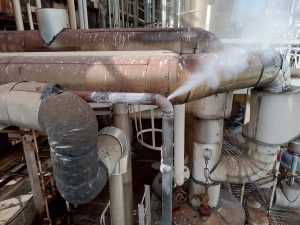
(圖示1說明: 某化工廠製程10 kg/cm²蒸氣管線沖蝕破洞因而蒸氣外洩。/A steam leak occurred in a 10 kg/cm² process line at a chemical plant due to erosion-induced pipe puncture. )
二、緒論 / II. Introduction
發電科技的演進始終伴隨著熱力學參數的提升。傳統次臨界機組的蒸氣壓力多受限於 170 kg/cm² 左右,而當代超臨界與超超臨界技術則突破了水的臨界點(225 kg/cm²),使得發電廠的主蒸氣與再熱蒸氣壓力常態化地運行於 247 kg/cm² 至 300 kg/cm² 之間,此一技術躍進不僅大幅降低了發電熱耗率(Heat Rate),亦顯著提升了整體能源轉換效率1。然而,極端的高溫高壓狀態賦予了蒸氣極高的流體動能與破壞潛力,特別是在管線幾何形狀發生急遽變化的彎管區段。當高速流體夾帶鍋爐剝落的氧化物微粒或在低負載階段凝結的微小液滴通過彎管時,巨大的慣性力與離心力會使這些離散相偏離主體流線,以極高的動能撞擊管壁,引發急劇的材料流失與管壁減薄。 The evolution of power generation technology has always been accompanied by the elevation of thermodynamic parameters. While traditional subcritical units’ steam pressures are mostly limited to around 170 kg/cm², contemporary supercritical and ultra-supercritical technologies have surpassed the critical point of water (225 kg/cm²), normalizing main steam and reheat steam pressures between 247 kg/cm² and 300 kg/cm². This technological leap has not only drastically reduced the plant heat rate but also significantly improved overall energy conversion efficiency1. However, extreme high-temperature and high-pressure conditions endow the steam with immense fluid kinetic energy and destructive potential, especially in bend sections where the pipeline’s geometry changes abruptly. When high-speed fluids carrying exfoliated oxide particles from the boiler or tiny droplets condensed during low-load phases pass through a bend, immense inertial and centrifugal forces cause these discrete phases to deviate from the main flow line. They impact the pipe wall with extremely high kinetic energy, triggering rapid material loss and wall thinning.
長久以來,石化與電力工業習慣於配管設計中採用標準化生產的 1.5D 長半徑(Long Radius, LR)對接銲彎頭2。1.5D 彎頭的曲率半徑僅為管外徑的 1.5 倍,其緊湊的幾何特性雖然節省了廠房空間,但極為陡峭的流道轉向卻成為流體力學上的致命傷。微粒在 1.5D 彎頭中往往以極具破壞性的大角度直接衝擊管壁盲端,造成高度集中的沖蝕熱區,甚至在短期內引發管線穿孔4。隨著數控冷作彎管技術(CNC Cold Bending)的成熟,工程界開始探討導入 3D 乃至 5D 大曲率半徑彎管的可行性5。大曲率半徑彎管不僅能使流體偏折過程更為平順,降低局部紊流強度與二次流效應,更能將微粒的撞擊角度由破壞力極強的垂直衝擊轉化為相對溫和的滑動摩擦,從根本上削弱沖蝕破壞的驅動力7。 For a long time, the petrochemical and power industries have conventionally utilized standardized 1.5D Long Radius (LR) butt-welded elbows in piping design2. The curvature radius of a 1.5D elbow is only 1.5 times the pipe’s outer diameter. Although its compact geometric characteristics save plant space, the extremely steep flow channel turn becomes a fatal flaw in fluid dynamics. Particles in 1.5D elbows often directly impact the blind end of the pipe wall at highly destructive large angles, creating highly concentrated erosion hotspots and even causing pipeline perforations in the short term4. With the maturation of CNC cold bending technology, the engineering community has begun exploring the feasibility of introducing large curvature radius bends, such as 3D and 5D5. Large curvature radius bends not only smooth the fluid deflection process and reduce local turbulence intensity and secondary flow effects, but they also transform the particle impact angle from a highly destructive perpendicular strike to a relatively mild sliding friction, fundamentally weakening the driving force of erosion damage7.
本研究的開展,即是基於上述工業痛點與技術演進。透過系統性地梳理沖蝕磨耗的微觀物理機制,並對比不同幾何曲率下流場結構的演化,進而結合材料科學與國際管線設計規範(ASME B31.1),建構一套針對 300 kg/cm² 超高壓蒸氣管線的完整防護與優化論述。同時,考量到 CCPP 機組因應再生能源間歇性而必須頻繁執行啟停(Cycling)操作的實務背景,本研究亦將管線柔性(Flexibility)、熱膨脹吸收能力以及業主與 EPC 的實務決策納入綜合評估,以期為超臨界發電廠的管路工程提供具前瞻性的解決方案。 This research is initiated based on the aforementioned industrial pain points and technological evolution. By systematically reviewing the microscopic physical mechanisms of erosive wear and comparing the evolution of flow field structures under different geometric curvatures, this study integrates material science and international piping design codes (ASME B31.1) to construct a comprehensive protection and optimization framework for 300 kg/cm² ultra-high pressure steam pipelines. Simultaneously, considering the practical background that CCPP units must frequently execute cycling operations to accommodate the intermittency of renewable energy, this study comprehensively evaluates pipeline flexibility, thermal expansion absorption capacity, and the practical decision-making of owners and EPCs, aiming to provide forward-looking solutions for the piping engineering of supercritical power plants.
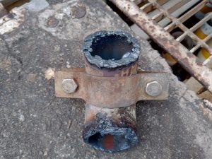
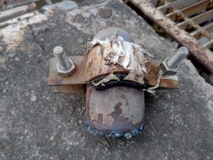
(圖示2&3說明: 無法停俥檢修暫時採取克漏方式阻止蒸氣洩漏。/Unable to shut down for repairs, an online leak-sealing method was temporarily applied to stop the steam leak.)
三、超高壓蒸氣環境下之沖蝕物理機制 / III. Physical Mechanisms of Erosion in Ultra-High Pressure Steam Environments
在 300 kg/cm² 與 600°C 以上的管線系統中,管壁材料的流失並非單一的化學腐蝕,而是由流體動力學與材料力學深度耦合的高能物理破壞過程。主要可歸納為固態微粒沖蝕(Solid Particle Erosion, SPE)與液滴撞擊沖蝕(Liquid Droplet Impingement, LDI)兩大核心機制。 In piping systems operating at 300 kg/cm² and temperatures above 600°C, the loss of pipe wall material is not solely due to chemical corrosion, but rather a high-energy physical destruction process deeply coupled with fluid dynamics and material mechanics. This can be primarily categorized into two core mechanisms: Solid Particle Erosion (SPE) and Liquid Droplet Impingement (LDI).
3.1 固態微粒沖蝕(SPE)與 Oka 理論模型 / 3.1 Solid Particle Erosion (SPE) and the Oka Theoretical Model
在高溫高壓運行條件下,鍋爐、熱回收蒸氣產生器(HRSG)的過熱器與再熱器管內壁會不可避免地生成一層磁鐵礦(Fe₃O₄)氧化皮。由於磁鐵礦的熱膨脹係數與基材合金鋼存在顯著差異,當 CCPP 機組經歷頻繁的負載升降或起停操作時,管線系統內部會產生劇烈的交變熱應力,導致這層堅硬且脆性的氧化皮發生剝落(Exfoliation)9。這些剝落的固態微粒被 300 kg/cm² 的高速蒸氣流夾帶,形成極具破壞力的氣固兩相流。當流體行經彎管時,微粒因自身質量與慣性較大,無法即時跟隨氣體的流線偏轉,進而直接撞擊彎管外背側(Extrados)的管壁,引發材料的微切削(Micro-cutting)、犁耕(Plowing)與反覆塑性變形,最終導致晶粒剝離12。 Under high-temperature and high-pressure operating conditions, the inner walls of superheaters and reheaters in boilers and Heat Recovery Steam Generators (HRSG) inevitably develop a layer of magnetite (Fe₃O₄) oxide scale. Due to the significant difference in thermal expansion coefficients between magnetite and the base alloy steel, when CCPP units undergo frequent load variations or start-stop cycling, severe alternating thermal stresses are generated within the piping system, leading to the exfoliation of this hard and brittle oxide layer9. These exfoliated solid particles are entrained by the 300 kg/cm² high-speed steam flow, forming a highly destructive gas-solid two-phase flow. As the fluid travels through a bend, particles with larger mass and inertia cannot immediately follow the gas flow streamlines; they directly impact the extrados of the bend, causing micro-cutting, plowing, and repeated plastic deformation of the material, which ultimately leads to grain spallation12.
為了精確預測與量化此一複雜的微觀破壞過程,工程界與學術界廣泛採用 Oka 沖蝕預測模型。相較於早期的 Finnie 模型主要針對延展性材料且在低衝擊角度下預測較為準確,或 McLaury 模型多用於泥漿液固兩相流,Oka 模型透過引入標的材料的維氏硬度(Vickers Hardness)作為核心變數,提供了更為全面且貼近實際工業材料表現的預測框架13。在 Oka 模型中,局部沖蝕率 E(α) 被定義為微粒衝擊角度α 的函數,其基本關係式如下: To accurately predict and quantify this complex microscopic destruction process, the engineering and academic communities widely adopt the Oka erosion prediction model. Compared to the early Finnie model, which is mainly accurate for ductile materials at low impact angles, or the McLaury model, mostly used for slurry liquid-solid flows, the Oka model introduces the target material’s Vickers Hardness as a core variable, providing a more comprehensive predictive framework that closely aligns with actual industrial material performance13. In the Oka model, the local erosion rate E(α) is defined as a function of the particle impact angle α, with the fundamental equation as follows:
E(α)=E90×g(α)
其中,E90 代表微粒以 90 度(垂直)撞擊管壁時的基準沖蝕損傷率,而 g(α) 則是描述沖蝕率如何隨衝擊角度變化的無因次歸一化函數。基準沖蝕率 E90 的決定極度依賴於微粒的衝擊速度與材料本身的機械性質,其展開式為: Here, E90 represents the baseline erosion damage rate when particles strike the wall at a 90-degree (perpendicular) angle, and g(α) is a dimensionless normalized function describing how the erosion rate varies with the impact angle. The determination of the baseline erosion rate E90 is heavily dependent on the particle impact velocity and the material’s mechanical properties, expanded as:
E90=K⋅(a⋅Hv )k1 ⋅(V/Vref )k2 ⋅(Dp/Dref )k3
式中, Hv為管線材料(如 P91/P92 鋼)的維氏硬度(GPa);V 為微粒實際撞擊速度,Vref 為參考速度;Dp為微粒直徑,Dref 為參考直徑;K、a、k1、 k2、k3 均為透過實驗擬合之常數與指數,其中速度指數 k2 的大小直接決定了流速對沖蝕率的非線性放大效應16。而角度依賴性函數 g(α) 則深刻揭示了幾何形狀對沖蝕的影響機制: Where Hv is the Vickers hardness of the pipeline material (e.g., P91/P92 steel) in GPa; V is the actual particle impact velocity, with Vref as the reference velocity; Dp is the particle diameter, with Dref as the reference diameter; and K, a, k1, k2, k3 are experimentally fitted constants and exponents, where the magnitude of the velocity exponent k2 directly determines the nonlinear amplification effect of flow velocity on the erosion rate16. The angle-dependent function g(α) profoundly reveals the mechanism by which geometry influences erosion:
g(α)=(sinα )n1⋅(1+Hv (1-sinα ))n2
指數 n1 與 n2 同樣與材料硬度及微粒特性高度相關4。大量實證數據與 CFD 數值模擬指出,對於具備良好延展性的超高壓管線用鋼,最嚴重的材料流失並非發生在 90 度的垂直撞擊,而是集中出現在 30° 至 50° 的淺角撞擊區間14。在此角度範圍內,微粒的切線速度分量與法線速度分量達到一種極具破壞性的平衡,切線分量促使微粒在金屬表面產生深長的犁溝,而法線分量則提供足夠的正向力壓迫金屬發生局部降伏。DNV-RP-O501 規範亦強烈呼應此一理論,強調流動方向的突變與撞擊角度的控制是管理固體微粒沖蝕的核心關鍵19。 The exponents n1 and n2 are also highly correlated with material hardness and particle characteristics4. Abundant empirical data and CFD simulations indicate that for ultra-high pressure pipeline steels with good ductility, the most severe material loss does not occur at a 90-degree perpendicular impact, but is concentrated in the shallow angle impact range of 30° to 50°14. Within this angle range, the tangential and normal velocity components of the particles reach a highly destructive balance; the tangential component causes the particles to create deep plowing grooves on the metal surface, while the normal component provides sufficient positive force to compel local yielding of the metal. The DNV-RP-O501 standard strongly echoes this theory, emphasizing that controlling sudden changes in flow direction and impact angles is the core key to managing solid particle erosion19.
此外,針對標題所強調的 600°C 超高溫環境,溫度與氧化膜響應的耦合效應對整體沖蝕率有著決定性的放大作用。學術研究指出,當管線運行溫度攀升至 600°C 時,不僅會加劇金屬表面氧化膜的厚度,微粒撞擊所造成的撞擊坑(Crater)深度也會顯著增加;同時,高溫會進一步強化沖蝕對流速的非線性依賴(Velocity dependence),這明確揭示了撞擊角度、流動速度、極端高溫與金屬表面氧化膜響應之間存在著深度的物理耦合14。因此,在高達 600°C 的環境下,流速與流場角度的些微惡化,皆會導致沖蝕破壞呈幾何級數般的激增。 Furthermore, addressing the 600°C ultra-high temperature environment emphasized in the title, the coupling effect of temperature and oxide film response plays a decisive amplifying role in the overall erosion rate. Academic research indicates that when the pipeline operating temperature climbs to 600°C, it not only exacerbates the thickness of the metal surface oxide film, but the depth of impact craters caused by particle strikes also increases significantly. Simultaneously, high temperatures further intensify the nonlinear dependence of erosion on velocity. This clearly reveals a profound physical coupling among impact angle, flow velocity, extreme high temperatures, and metal surface oxide film responses14. Therefore, in environments up to 600°C, even slight deteriorations in flow velocity or flow field angles will lead to an exponential surge in erosion damage.
3.2 液滴撞擊沖蝕(LDI)與 Heymann 水錘效應 / 3.2 Liquid Droplet Impingement (LDI) and Heymann’s Water Hammer Effect
除了固態微粒,超高壓管線在特定運行條件下亦面臨液滴撞擊的嚴峻威脅。在 CCPP 機組的冷態啟動、低負載運行或降載過渡期間,主蒸氣可能無法維持完全的超熱狀態,導致管線內部出現汽水兩相流或夾帶高速濕蒸氣(Wet Steam)液滴22。當這些微小但高速運動的液滴撞擊金屬彎管表面時,其破壞機制與固態微粒截然不同,主要依賴於液體壓縮性所引發的極端瞬態壓力。 In addition to solid particles, ultra-high pressure pipelines face severe threats from liquid droplet impingement under specific operating conditions. During cold starts, low-load operations, or de-loading transition periods of CCPP units, the main steam may fail to maintain a completely superheated state, resulting in a steam-water two-phase flow or the entrainment of high-speed wet steam droplets within the pipeline22. When these tiny but high-speed droplets impact the metal bend surface, their destruction mechanism differs entirely from that of solid particles, relying primarily on extreme transient pressures induced by liquid compressibility.
液滴撞擊瞬間的物理行為可透過 Heymann 提出的水錘壓力(Water Hammer Pressure)理論進行深度解析。當具有曲面特徵的液滴以速度 Vimpact 接近並接觸固體表面時,在接觸的初始極短瞬間,液滴與管壁的接觸面積擴張速度會超過液體內部的激波(Shock Wave)傳遞速度。這導致液滴內部的液體無法即時向外排擠,呈現高度壓縮狀態24。此時,撞擊中心區域產生的壓力 Pimpact 可由以下方程式估算: The physical behavior at the moment of droplet impact can be deeply analyzed through the Water Hammer Pressure theory proposed by Heymann. When a droplet with curved features approaches and contacts a solid surface at a velocity of Vimpact, during the initial extremely brief moment of contact, the expansion speed of the contact area between the droplet and the pipe wall exceeds the propagation speed of the shock wave inside the liquid. This causes the liquid inside the droplet to be unable to squeeze outwards immediately, presenting a highly compressed state24. At this time, the pressure Pimpact generated in the central impact region can be estimated by the following equation:
Pimpact=ρl Cl Vimpact
在此方程式中,ρl 為液滴的質量密度,Cl 為聲波在該液體介質中的傳播速度(代表激波速度)24。更為致命的是,Heymann 模型指出,在液滴接觸邊緣(Contact edge)處,壓力會進一步疊加激化,其最高峰值甚至可達到3ρl Cl Vimpact 18。 In this equation, ρl is the mass density of the droplet, and Cl is the propagation speed of sound waves in the liquid medium (representing the shock wave speed)24. Even more fatally, Heymann’s model points out that at the droplet contact edge, the pressure will further superimpose and intensify, and its peak value can even reach 3ρl Cl Vimpact 18.
從微觀時間尺度來看,若液滴半徑為 r,極端壓縮與高壓狀態將持續約 3rVimpact/ 2CI2 的時間區間18。儘管作用時間極短,但 300 kg/cm² 系統中的高流速足以使此瞬態峰值壓力輕易突破 P91/P92 材料的降伏強度與疲勞極限。反覆的超高壓液滴撞擊會在金屬表面誘發微裂紋網,最終導致大塊金屬晶粒的剝落。研究表明,液滴撞擊沖蝕率與撞擊速度呈現極高的非線性依賴關係,其速度指數通常介於 4 至 5 之間,這意味著流速的微小增加將導致沖蝕率呈幾何級數飆升24。因此,在幾何設計上有效降低彎管外側的局部最大流速,對於防範 LDI 至關重要。 From a microscopic time scale, if the droplet radius is r, the state of extreme compression and high pressure will last for a time interval of approximately 3rVimpact/ 2CI2 18. Although the duration is extremely short, the high flow velocity in a 300 kg/cm² system is sufficient to allow this transient peak pressure to easily surpass the yield strength and fatigue limit of P91/P92 materials. Repeated ultra-high pressure droplet impacts will induce a network of microcracks on the metal surface, eventually leading to the spallation of large metal grains. Research indicates that the liquid droplet impingement erosion rate has a highly nonlinear dependence on impact velocity, with a velocity exponent typically ranging between 4 and 5. This implies that a slight increase in flow velocity will cause the erosion rate to skyrocket exponentially24. Therefore, effectively reducing the local maximum flow velocity on the extrados of the bend through geometric design is crucial for preventing LDI.
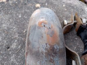
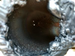
(圖示4&5說明: 蒸氣1.5D彎徑管線沖蝕現象造成2個洞。/Erosion in the 1.5D elbow steam pipe resulted in two pinholes/punctures.)
四、彎管幾何參數演進與流體動力學特徵 / IV. Evolution of Bend Geometry Parameters and Fluid Dynamic Characteristics
理解了沖蝕的微觀破壞機制後,即可將焦點轉移至管線系統中流體流向改變的幾何載體——彎管。曲率半徑的大小不僅決定了管線的物理佔地空間,更從根本上主導了內部流場的宏觀結構、紊流強度以及二次流的演化。 Having understood the microscopic destruction mechanisms of erosion, the focus can shift to the geometric carriers that alter fluid direction in piping systems—pipe bends. The size of the curvature radius not only dictates the physical footprint of the pipeline but also fundamentally governs the macroscopic structure of the internal flow field, turbulence intensity, and the evolution of secondary flows.
4.1 1.5D 銲接彎頭與 3D/5D 冷作彎管之工程定義 / 4.1 Engineering Definitions of 1.5D Welded Elbows and 3D/5D Cold Bends
在工業配管實務中,彎曲半徑通常以管線的公稱外徑(Nominal Outside Diameter, D)為基準進行定義。傳統上最廣泛應用的標準管件為 1.5D 長半徑(Long Radius, LR)彎頭,其幾何曲率半徑 R 精確等於管外徑的 1.5 倍(R=1.5D)。這類彎頭通常由管件製造廠透過熱推製或鍛造工法標準化大量生產,並在施工現場透過兩端的對接銲接(Butt Weld)與直管段相連2。1.5D 彎頭的優勢在於體積小巧、空間適應性強,但在超高壓與高流速應用中,其幾何劣勢被無限放大。 In industrial piping practice, the bending radius is typically defined based on the nominal outside diameter (D) of the pipe. The most widely used standard fitting traditionally is the 1.5D Long Radius (LR) elbow, whose geometric curvature radius R equals exactly 1.5 times the pipe’s outer diameter (R=1.5D). These elbows are generally mass-produced by fitting manufacturers using hot induction pushing or forging methods and are connected to straight pipe segments on-site via butt welds at both ends2. The advantages of 1.5D elbows lie in their compact size and high spatial adaptability, but their geometric disadvantages are infinitely magnified in ultra-high pressure and high-velocity applications.
相對而言,3D 與 5D 彎管(其曲率半徑分別為外徑的 3 倍與 5 倍,即R=3D 與 R=5D)通常被歸類為大半徑彎管。這類管件極少採用模具鍛造,而是利用先進的數控(CNC)彎管機,直接對原材直管進行冷作物理彎曲(Cold Bending)。這種工法使得整段彎曲過渡區一體成型,消除了 1.5D 彎頭兩端必定存在的過渡銲道,維持了管壁微觀組織的連續性,並提供了更為平緩的流體導引路徑2。 In contrast, 3D and 5D bends (with curvature radii of 3 times and 5 times the outer diameter, i.e., R=3D and R=5D) are generally classified as large-radius bends. Such fittings are rarely die-forged; instead, they are formed by directly subjecting straight raw pipes to physical cold bending using advanced CNC bending machines. This method allows the entire curved transition zone to be integrally formed, eliminating the transition welds that inevitably exist at both ends of a 1.5D elbow, maintaining the continuity of the pipe wall’s microstructure, and providing a much smoother fluid guidance path2.
4.2 狄恩數(Dean Number)效應與二次流結構 / 4.2 Dean Number Effect and Secondary Flow Structure
當超高壓蒸氣高速流經彎管時,流體微團被迫沿著曲線軌跡運動,進而產生強大的離心力。這種離心力將管中心流速較快、動能較大的流體甩向彎管的外背側(Extrados),導致外側壓力升高;同時,靠近管壁邊界層內流速較慢的流體,受到此一徑向逆壓梯度的驅動,會沿著管壁由外側回流至內腹側(Intrados)。這種結合了主軸向流動與橫截面徑向環流的複雜三維流動,在彎管截面上形成了一對對稱且反向旋轉的二次渦流,在流體力學中被稱為狄恩渦流(Dean Vortices)22。 When ultra-high pressure steam flows through a pipe bend at high speeds, fluid parcels are forced to move along a curved trajectory, generating strong centrifugal forces. This centrifugal force flings the faster-moving, higher-kinetic-energy fluid from the pipe’s center towards the extrados of the bend, causing the pressure on the outer side to rise. Simultaneously, the slower-moving fluid near the wall’s boundary layer, driven by this radial adverse pressure gradient, flows back from the outside along the wall to the intrados. This complex three-dimensional flow, combining main axial flow with cross-sectional radial circulation, forms a pair of symmetrical, counter-rotating secondary vortices on the bend cross-section, known in fluid mechanics as Dean vortices22.
衡量彎管內二次流強度與流場紊亂程度的核心無因次參數為狄恩數(De),其數學定義結合了代表慣性力與黏滯力比值的雷諾數(Re),以及彎管的幾何特徵31: The core dimensionless parameter measuring the intensity of secondary flows and flow field turbulence in a pipe bend is the Dean number (De). Its mathematical definition combines the Reynolds number (Re), which represents the ratio of inertial to viscous forces, and the geometric characteristics of the bend31:
De=Re√D/2R
透過此方程式可以清晰洞察曲率半徑 R 對流場的決定性影響。當選用 1.5D 彎頭時,分母中的 2R 值較小,導致√D/2R 乘數變大,在相同超高壓雷諾數操作條件下,狄恩數將急遽攀升33。高狄恩數意味著極端強烈的二次渦流與高度不穩定的紊流邊界層。在 1.5D 彎頭內部,強大的狄恩渦流不僅造成流速分佈極度扭曲(最高流速區緊貼外背側管壁),更會將氣流中夾帶的氧化物微粒無情地「掃向」外側盲端,加劇局部微粒濃度與撞擊動能4。 This equation provides clear insight into the decisive impact of the curvature radius R on the flow field. When a 1.5D elbow is selected, the smaller 2R value in the denominator results in a larger multiplier √D/2R. Under the same ultra-high pressure Reynolds number operating conditions, the Dean number will surge dramatically33. A high Dean number implies extremely intense secondary vortices and highly unstable turbulent boundary layers. Inside a 1.5D elbow, strong Dean vortices not only cause severe distortion in velocity distribution (with the highest velocity zone clinging to the extrados wall) but also ruthlessly “sweep” the entrained oxide particles toward the outer blind end, intensifying local particle concentration and impact kinetic energy4.
反之,當管線設計升級為 5D 大半徑冷作彎管時,曲率半徑大幅增加使得狄恩數顯著下降。二次流的發展受到有效抑制,流場的主軸向動能得以平順過渡,截面上的速度梯度趨於和緩。這種流動特徵的根本改變,極大地降低了微粒被強行甩向管壁的機率,是 5D 彎管抗沖蝕性能優異的流體力學基礎22。 Conversely, when the pipeline design is upgraded to a 5D large-radius cold bend, the substantial increase in curvature radius significantly lowers the Dean number. The development of secondary flow is effectively suppressed, the main axial kinetic energy of the flow field transitions smoothly, and the velocity gradient across the cross-section becomes milder. This fundamental change in flow characteristics greatly reduces the probability of particles being forcibly flung against the pipe wall, forming the fluid dynamic foundation for the excellent anti-erosion performance of 5D bends22.
4.3 串聯彎管效應與壓力降優化 / 4.3 Effects of Bends in Series and Pressure Drop Optimization
在複雜的 CCPP 工廠佈局中,主蒸氣管線鮮少只包含單一彎管,更多是以串聯形式(Elbows in Series)存在以閃避結構物。學術研究指出,串聯彎管的排列方式與間距會對下游管件的沖蝕產生劇烈影響。例如,在 Π 型或 Z 型的串聯配置中,若兩彎管間距僅為 3 倍管徑左右,前導彎頭產生的強烈二次流尾流(Wake flow)來不及消散,會直接侵入第二個彎管,導致第二彎管出現異常集中的次級沖蝕高峰,其最大沖蝕率甚至可能超越首個彎頭7。 In complex CCPP plant layouts, main steam pipelines rarely consist of only a single bend; more often, they exist in series (Elbows in Series) to bypass structures. Academic research indicates that the arrangement and spacing of bends in series drastically impact the erosion of downstream fittings. For example, in U-type (Π-type) or Z-type series configurations, if the distance between two bends is only about 3 times the pipe diameter, the intense secondary flow wake generated by the leading elbow does not have time to dissipate. It intrudes directly into the second bend, causing an abnormally concentrated secondary erosion peak in the second bend, where the maximum erosion rate may even exceed that of the first elbow7.
在這種串聯配置中,1.5D 彎頭的高壓降與高尾流擾動特性成為系統的致命弱點。相對地,採用 3D 或 5D 彎管不僅能拉長流動過渡距離,促進尾流的提早消散,更能大幅降低整段管線的總壓力損失係數(Loss Coefficient, K)。根據水力學阻力理論,5D 彎管的壓降遠小於 1.5D 彎頭,這使得在 300 kg/cm² 系統中,蒸氣能以更高的焓值與壓力送達汽輪機入口,直接貢獻於發電廠整體熱效率的微幅提升,在長達數十年的生命週期中創造可觀的經濟效益2。 In such series configurations, the high pressure drop and high wake disturbance characteristics of 1.5D elbows become fatal weaknesses in the system. In contrast, using 3D or 5D bends not only lengthens the flow transition distance, promoting earlier dissipation of wakes, but also significantly reduces the total pressure loss coefficient (K) of the entire pipeline section. According to hydraulic resistance theory, the pressure drop of a 5D bend is much smaller than that of a 1.5D elbow. In a 300 kg/cm² system, this allows steam to be delivered to the turbine inlet with higher enthalpy and pressure, directly contributing to a marginal increase in the overall thermal efficiency of the power plant and generating considerable economic benefits over a multi-decade life cycle2.
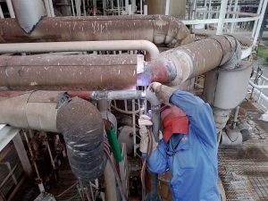
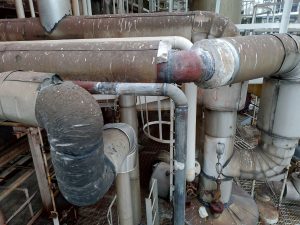
(圖示6&7說明: 氬銲銲接作業及修復後情形。/TIG welding was performed, and the repair outcome has been verified.)
五、數值模擬(CFD)與曲率優化之減磨效益評估 / V. Numerical Simulation (CFD) and Wear Reduction Evaluation of Curvature Optimization
5.1 Eulerian-Lagrangian 數值模擬架構 / 5.1 Eulerian-Lagrangian Numerical Simulation Framework
在當代的 CFD 沖蝕模擬中,通常採用 Eulerian-Lagrangian 兩相流耦合架構。超高壓蒸氣被視為連續相(Eulerian approach),透過求解納維-斯托克斯方程式(Navier-Stokes equations)並搭配合適的紊流模型(如 Realizable k-ε或 SST k-ω)來獲取流場的速度與壓力分佈;而剝落的氧化鐵微粒或水滴則被視為離散相(Lagrangian approach),透過牛頓運動定律追蹤大量單一微粒的軌跡4。 In contemporary CFD erosion simulations, the Eulerian-Lagrangian two-phase coupled framework is commonly employed. The ultra-high pressure steam is treated as the continuous phase (Eulerian approach). By solving the Navier-Stokes equations coupled with suitable turbulence models (such as Realizable k-ε or SST k-ω), the velocity and pressure distribution of the flow field are obtained. Meanwhile, exfoliated iron oxide particles or water droplets are treated as the discrete phase (Lagrangian approach), and the trajectories of numerous individual particles are tracked using Newton’s laws of motion4.
離散相微粒在流場中的受力極為複雜,主要方程式可表達為: The forces exerted on discrete phase particles in the flow field are extremely complex, and the main equation can be expressed as:
mp (dup/dt)=FD+FP+Fg+FA
其中,FD 為連續相施加於微粒的曳力(Drag Force),FP 為壓力梯度力,Fg 為重力與浮力,FA 為虛擬質量力(Virtual Mass Force)17。透過精確計算這些受力,CFD 模型能夠準確預測微粒撞擊管壁的精確位置、瞬間速度與角度,並將這些參數輸入前述的 Oka 模型中計算局部質量流失率15。為了確保模擬的準確性,高質量的網格劃分與網格收斂指數(Grid Convergence Index, GCI)驗證是必不可少的步驟,以消除數值離散化誤差對沖蝕極值預測的干擾7。 Where FD is the drag force exerted by the continuous phase on the particle, FP is the pressure gradient force, Fg is gravity and buoyancy, and FA is the virtual mass force17. By accurately calculating these forces, CFD models can precisely predict the exact locations, instantaneous velocities, and angles at which particles impact the pipe wall, feeding these parameters into the aforementioned Oka model to compute local mass loss rates15. To ensure simulation accuracy, high-quality meshing and Grid Convergence Index (GCI) verification are indispensable steps to eliminate the interference of numerical discretization errors on the prediction of erosion extremes7.
5.2 曲率半徑演進對沖蝕熱區分佈之影響比較 / 5.2 Comparison of the Impact of Curvature Radius Evolution on Erosion Hotspot Distribution
整合大量實證數據與 CFD 模擬結果,將彎管幾何從 1.5D 逐步升級至 3D 乃至 5D,其沖蝕特徵呈現出戲劇性的轉變: By integrating massive empirical data and CFD simulation results, progressively upgrading the bend geometry from 1.5D to 3D and ultimately 5D reveals a dramatic transformation in erosion characteristics:
- 1.5D 銲接彎頭的極端磨耗特徵 (Extreme Wear Characteristics of 1.5D Welded Elbows):在 1.5D 的緊湊空間內,氣流發生急轉彎,慣性極大的微粒完全脫離流線。CFD 軌跡圖顯示,微粒宛如散彈槍般集中轟擊彎頭外背側約 40° 至 50° 的區域。此處的撞擊角度陡峭,導致局部沖蝕率(Maximum Erosion Rate)呈現極度尖銳的峰值,是工安事故的高發熱區4。 Within the compact space of a 1.5D elbow, the airflow takes a sharp turn, causing high-inertia particles to completely detach from streamlines. CFD trajectory plots show particles bombarding the extrados of the elbow in a concentrated, shotgun-like manner at roughly the 40° to 50° region. The impact angles here are steep, leading the Maximum Erosion Rate to exhibit an extremely sharp peak, making it a high-risk hotspot for industrial safety incidents4.
- 3D 冷作彎管的過渡緩解 (Transitional Mitigation in 3D Cold Bends):當曲率半徑擴展至 3D,流線開始變得和緩。二次流的強度受到一定程度的抑制,微粒撞擊管壁的角度開始轉向淺角切削。沖蝕熱區的面積明顯擴大,局部最大沖蝕率相較於5D 彎頭已有顯著(約降低 25% 至 40%)的改善4。 As the curvature radius expands to 3D, the streamlines become gentler. The intensity of secondary flows is somewhat suppressed, and the particle impact angles shift towards shallow-angle cutting. The area of the erosion hotspot expands significantly, and the local maximum erosion rate sees substantial improvement (a reduction of about 25% to 40%) compared to 1.5D elbows4.
- 5D 冷作彎管的全面防護效益 (Comprehensive Protection Benefits of 5D Cold Bends):微粒有足夠的過渡空間受流體曳力牽引,軌跡逐漸與管壁平行,絕大多數撞擊轉變為極小角度的掠過(Glancing)或滑移(Sliding)8。數值實驗與物理塗漆磨耗測試皆證實,將曲率半徑提升至 5D,最大局部沖蝕率可獲得高達 66% 的斷崖式縮減,磨耗均勻地分散於廣闊的管壁上8。 Particles are given sufficient transitional space to be guided by fluid drag forces, aligning their trajectories almost parallel to the pipe wall. The vast majority of impacts transform into very shallow-angle glancing or sliding8. Both numerical experiments and physical paint erosion tests confirm that increasing the curvature radius to 5D achieves a cliff-like reduction of up to 66% in the maximum local erosion rate, distributing the wear evenly across a broad expanse of the pipe wall8.
| 彎管幾何類型 (Bend Geometry Type) | 狄恩渦流強度 (Dean Vortex Intensity) | 微粒主要撞擊角度 (Primary Particle Impact Angle) | 沖蝕熱區分佈特徵 (Erosion Hotspot Distribution) | 最大沖蝕率預測 (Predicted Max Erosion Rate) |
| 1.5D 銲接彎頭 (1.5D Welded Elbow) | 極高 (Very High) | 大角度直接衝擊 (Large-angle direct impact) | 極度集中於外背側盲端 (Highly concentrated at extrados blind end) | 100% (基準熱區 Base reference) |
| 3D 冷作彎管 (3D Cold Bend) | 中等 (Medium) | 中淺角度撞擊 (Medium-shallow angle impact) | 熱區擴散,峰值平緩 (Hotspot diffuses, peak flattens) | 約 (Approx.) 60% – 75% |
| 5D 冷作彎管 (5D Cold Bend) | 低 (Low) | 極淺角滑移 (Extremely shallow glancing/sliding) | 廣泛分散 (Broadly dispersed) | 約 (Approx.) 30% – 40% |
六、ASME B31.1 規範解析與先進材料防護技術 / VI. ASME B31.1 Code Analysis and Advanced Material Protection Technologies
在確立了 5D 彎管的流體力學優勢後,300 kg/cm² 超高壓系統的落實仍需仰賴嚴謹的結構設計規範與尖端的材料冶金技術。ASME B31.1 動力管線規範(Power Piping Code)為此類高能系統提供了權威的安全準則。 Having established the fluid dynamic advantages of 5D bends, implementing 300 kg/cm² ultra-high pressure systems still relies on rigorous structural design codes and cutting-edge material metallurgy. The ASME B31.1 Power Piping Code provides authoritative safety guidelines for such high-energy systems.
6.1 管壁厚度設計與成型減薄補償 / 6.1 Wall Thickness Design and Forming Thinning Compensation
超高壓管線在承受巨大的內部壓力時,管壁會產生環向應力(Hoop Stress)。當直管被彎曲成彎管時,材料會發生劇烈的塑性流動——彎管外背側(Extrados)受到拉伸而減薄,內腹側(Intrados)則受到擠壓而增厚41。為確保彎曲後的各部位厚度仍能安全承受極高內壓,ASME B31.1 強制引入了形狀補償係數 I(Intrados/Extrados factor)來修正計算公式42。 When ultra-high pressure pipelines endure immense internal pressure, hoop stress is generated in the pipe wall. When a straight pipe is bent, the material undergoes severe plastic flow—the extrados is stretched and thinned, while the intrados is compressed and thickened41. To ensure the bent sections can safely withstand extreme internal pressure, ASME B31.1 mandates the introduction of a shape compensation factor, the I factor (Intrados/Extrados factor), to correct the calculation formulas42.
對於內側(Intrados),修正係數為 (For Intrados, the correction factor is):
I=(4(R/D)-1)/(4(R/D)-2)
對於外側(Extrados),修正係數為 (For Extrados, the correction factor is):
I=(4(R/D)+1)/(4(R/D)+2)
將 R/D=1.5代入公式可知,1.5D 彎頭外側的 I 值相對較低,代表為了抵銷減薄,原始胚管必須具備極大的厚度裕度(Over-thickness)。相對而言,當採用 5D 彎管(R/D=5)時,外側的 I 值計算結果高達 0.954,幾乎趨近於 1。這表示 5D 彎管在受力狀態與幾何變化上極度接近完美直管,成型過程中的拉伸減薄率微乎其微45。採用 5D 冷作彎管不僅大幅節省了厚壁高價鋼材的採購成本,更維持了管壁厚度的均勻性,從結構力學角度提升了管線的抗壓與抗疲勞能力43。 Substituting R/D=1.5 into the formula shows that the I value for the extrados of a 1.5D elbow is relatively low, meaning that to offset thinning, the raw mother pipe must have a massive thickness margin (over-thickness). Conversely, when using a 5D bend (R/D=5), the calculated I value for the extrados reaches 0.954, nearly approaching 1. This indicates that 5D bends are extremely close to perfect straight pipes in terms of stress states and geometric changes, with minimal tensile thinning during forming45. Utilizing 5D cold bends not only slashes the procurement costs of thick-walled, expensive steel but also maintains uniform wall thickness, enhancing the pipeline’s pressure and fatigue resistance from a structural mechanics perspective43.
6.2 P91/P92 材料冶金特性與感應式彎後熱處理(PBHT) / 6.2 Metallurgical Characteristics of P91/P92 Materials and Induction Post-Bend Heat Treatment (PBHT)
為了抵抗 600°C 以上高溫環境下的金屬潛變(Creep),超高壓主蒸氣管線目前幾乎全面採用潛變強化鐵素體鋼(CSEF),其中以 P91 及 P92 最為關鍵47。這些合金鋼透過析出微量碳氮化物釘紮差排,展現驚人高溫強度49。然而,當管材被冷作彎曲成 3D 或 5D 彎管時,劇烈的塑性變形會破壞強化機制50。因此,依據 ASME B31.1 規範,P91/P92 鋼材冷彎後必須執行嚴格的彎後熱處理(PBHT)48。 To resist metal creep in environments exceeding 600°C, ultra-high pressure main steam pipelines almost universally employ Creep Strength Enhanced Ferritic Steels (CSEF), particularly P91 and P9247. These alloys exhibit astonishing high-temperature strength by precipitating trace carbonitrides that pin dislocations49. However, when pipes are cold-bent into 3D or 5D bends, severe plastic deformation disrupts these strengthening mechanisms50. Therefore, according to the ASME B31.1 code, P91/P92 steels must undergo rigorous Post-Bend Heat Treatment (PBHT) after cold bending48.
PBHT 要求持溫(Soaking)區間必須嚴格鎖定在 730°C 至 760°C,且依據管壁厚度有嚴格的時間規定52。現代實務多改採高頻感應式熱處理技術(Induction Heating, IH),透過交變磁場使管壁內部產生渦電流自體發熱,確保管壁內外層溫度的極度一致,是 P91/P92 5D 冷作彎管製造過程中的核心工法保障51。 PBHT mandates that the soaking temperature range must be strictly locked between 730°C and 760°C, with strict time requirements based on wall thickness52. Modern practice increasingly adopts high-frequency Induction Heating (IH) technology, which generates eddy currents via alternating magnetic fields to heat the pipe wall from within. This ensures extreme temperature consistency between the inner and outer layers of the pipe wall, serving as a core procedural safeguard in the manufacturing of P91/P92 5D cold bends51.
6.3 雷射熔覆(Laser Cladding)表面防護技術的應用潛力 / 6.3 Application Potential of Laser Cladding Surface Protection Technology
在廠房狹小空間或特定節點無法佈置龐大 5D 彎管而被迫採用 1.5D 彎頭時,雷射熔覆(Laser Cladding)技術成為最後一道防線。該工法利用高功率雷射將具備極高耐磨性與抗高溫氧化能力的合金粉末(如鈷基 Stellite 合金)熔化並凝固於管內壁53。相較於傳統熱噴塗,雷射熔覆與母材形成極強的冶金結合,稀釋率極低(僅 5%~8%),且熱影響區極窄,能精準沉積抗磨裝甲,大幅延長管線組件在極端環境下的免維護週期53。 When compact plant spaces or specific nodes prevent the installation of massive 5D bends, forcing the use of 1.5D elbows, Laser Cladding technology emerges as the final line of defense. This method utilizes high-power lasers to melt and solidify highly wear- and oxidation-resistant alloy powders (e.g., cobalt-based Stellite alloys) onto the inner pipe wall53. Compared to traditional thermal spraying, laser cladding forms a robust metallurgical bond with the substrate, features an extremely low dilution rate (only 5%~8%), and possesses a narrow heat-affected zone. It accurately deposits anti-wear armor, significantly extending the maintenance-free cycle of piping components in extreme environments53.
七、CCPP 廠區實務佈置與熱力學佈局優化 / VII. Practical Layout of CCPP Plants and Thermodynamic Layout Optimization
7.1 空間限制與管線柔性(Flexibility)分析 / 7.1 Space Constraints and Piping Flexibility Analysis
CCPP 機組為彌補再生能源間歇性,需承受極度頻繁的起停循環60。管線由冷態升至超高溫時會產生可觀的熱膨脹位移。1.5D 銲接彎頭幾何剛性極大,無法吸收應力,且兩端銲道易成熱疲勞裂紋萌生點39。相反地,一體成型的 3D/5D 冷作彎管賦予管線極佳的「柔性」,如同彈簧般優雅吸收熱膨脹位移,降低端點載荷,減少支撐架設置60。 To compensate for the intermittency of renewable energy, CCPP units must endure extremely frequent start-stop cycles60. Pipelines undergo considerable thermal expansion displacement when heating from a cold state to ultra-high temperatures. 1.5D welded elbows possess immense geometric rigidity, making them unable to absorb stress, and the welds at both ends are prone to becoming initiation points for thermal fatigue cracks39. Conversely, integrally formed 3D/5D cold bends grant the pipeline excellent “flexibility,” gracefully absorbing thermal expansion displacement like a spring, reducing terminal loads, and minimizing the need for rigid pipe supports60.
7.2 熱層化(Thermal Stratification)現象之緩解 / 7.2 Mitigation of Thermal Stratification Phenomena
管內凝結水積聚與高溫蒸氣並存的熱層化現象會引發巨大熱應力與管徑翹曲61。1.5D 彎頭的強烈渦流會造成局部熱震盪;而 5D 彎管能促進流體和緩自然對流,避免冷熱區塊劇烈交替。因此,新工程應摒棄追求空間緊湊的舊思維,優先選擇 3D/5D 冷作彎管以兼顧流場抗沖蝕效能與系統柔性22。 Thermal stratification—the coexistence of pooled condensate and high-temperature steam in a pipe—induces tremendous thermal stress and pipe bowing61. The intense vortices in a 1.5D elbow cause local thermal striping; whereas 5D bends promote gentle natural convection of the fluid, avoiding the violent alternation of hot and cold zones. Therefore, new engineering projects should discard outdated mindsets focused purely on space compactness, prioritizing 3D/5D cold bends to balance flow field anti-erosion performance and system flexibility22.
八、工程實務與決策分析:業主、EPC與專業承包商之協同效應 / VIII. Engineering Practice and Decision Analysis: Synergistic Effects of Owners, EPCs, and Specialized Contractors
8.1 業主(如台電)對於 P91/P92 蒸氣管線彎管之選取考量 / 8.1 Owners’ (e.g., Taipower) Considerations for Selecting P91/P92 Steam Pipe Bends
業主高度重視發電熱效率與生命週期成本。3D/5D 彎管能顯著降低流損,確保蒸氣以更高壓力送達汽輪機。此外,平順流場大幅降低管壁減薄率,防止突發穿孔與非預期停機。因此業主在技術審查階段更傾向將 3D/5D 彎管列為首選1。 Owners highly value power generation thermal efficiency and lifecycle costs. 3D/5D bends significantly reduce flow losses, ensuring steam is delivered to the turbine at higher pressures. Moreover, the smoothed flow field drastically lowers pipe wall thinning rates, preventing sudden perforations and unplanned outages. Consequently, during technical review stages, owners are far more inclined to designate 3D/5D bends as the preferred option1.
8.2 EPC 統包商在彎管選型上之抉擇與成本評估 / 8.2 EPC Contractors’ Choices and Cost Evaluation in Bend Selection
EPC 統包商需考量建造成本與時程。1.5D 彎頭需兩道現場銲道,P91 現場銲接繁瑣且需 100% 射線檢驗(RT),重銲風險高48。選用 3D/5D 冷作彎管可免除過渡銲道,降低對高階配管工的依賴與 RT 檢測風險,極大化壓縮現場施工時程。 EPC contractors must consider construction costs and schedules. A 1.5D elbow requires two on-site welds; P91 on-site welding is tedious, demands 100% Radiographic Testing (RT), and carries a high risk of re-welding48. Utilizing 3D/5D cold bends eliminates transition welds, reducing reliance on high-tier pipe fitters and mitigating RT inspection risks, thereby maximizing the compression of on-site construction schedules.
8.3 潁璋工程「三合一工法」在 CCPP 實務操作下之綜合效益 / 8.3 Comprehensive Benefits of Yingzhang Engineering’s “Three-in-One Method” in CCPP Practical Operations
專業管線處理廠(如潁璋工程)提出「CNC 冷作彎管」、「高頻感應式熱處理(PBHT)」與「專案成本管控效益」結合的「三合一工法」66。此工法優化了物料與倉儲,雙重下降了品質檢驗成本,並透過廠內精準 PBHT 確保材料潛變強度的恢復,完美契合 CCPP 高效率、高安全性的建造指標28。 Professional piping processing plants (such as Yingzhang Engineering) propose a “Three-in-One Method,” which integrates “CNC Cold Bending,” “High-Frequency Induction Post-Bend Heat Treatment (PBHT),” and “Project Cost Control Benefits”66. This method optimizes materials and warehousing, dually reduces quality inspection costs, and ensures the recovery of material creep strength through precise in-factory PBHT, perfectly matching the high-efficiency, high-safety construction metrics of CCPPs28.
九、結論 / IX. Conclusions
本研究透過跨領域的深度探討,全面解析了 300 kg/cm² 超高壓蒸氣管線在現代超臨界發電廠中所面臨的極端物理挑戰,並針對幾何形狀優化、材料防護工法及工程實務決策提出系統性的評估,茲將核心結論歸納如下: Through deep, cross-disciplinary exploration, this study comprehensively analyzes the extreme physical challenges faced by 300 kg/cm² ultra-high pressure steam pipelines in modern supercritical power plants, systematically evaluating geometric shape optimization, material protection methods, and engineering practice decisions. The core conclusions are summarized as follows:
- 沖蝕機制的幾何高度依賴性與高溫耦合效應 (Geometric Dependence and High-Temperature Coupling Effects of Erosion Mechanisms):超高壓管線磨耗由 SPE 與 LDI 主導。600°C 左右的高溫會顯著劣化金屬硬度並強化流速對沖蝕率的放大作用,凸顯了幾何設計優化的急迫性。 Ultra-high pressure pipeline wear is dominated by SPE and LDI. High temperatures around 600°C significantly degrade metal hardness and amplify the flow velocity’s effect on erosion rates, highlighting the urgency of geometric design optimization.
- 5D 冷作彎管的壓倒性流體力學優勢 (Overwhelming Fluid Dynamic Advantages of 5D Cold Bends):5D 冷作彎管能徹底平順化流場,將微粒撞擊轉化為極淺角滑移,使局部最大沖蝕率獲得高達 66% 的縮減,徹底解決盲端穿孔隱患。 5D cold bends thoroughly smooth the flow field, transforming particle impacts into extremely shallow-angle sliding, achieving up to a 66% reduction in the maximum local erosion rate and completely resolving the risk of blind-end perforation.
- ASME 規範下的厚度經濟性與熱應力柔性 (Thickness Economy and Thermal Stress Flexibility under ASME Codes):5D 彎管形狀補償係數極低,避免了 P91/P92 管材厚度浪費,且一體成型設計賦予卓越柔性,完美吸收熱膨脹位移。 5D bends have an extremely low shape compensation factor, avoiding the waste of P91/P92 pipe thickness. The integrally formed design imparts outstanding flexibility, perfectly absorbing thermal expansion displacement.
- 精密材料防護與工程實務的協同效應 (Synergistic Effects of Precision Material Protection and Engineering Practice):針對空間受限區,雷射熔覆提供抗磨裝甲;宏觀工程上,整合 CNC 冷作彎管與精準 PBHT 的工法,能兼顧 EPC 預算工期與業主長效安全性。 For space-constrained areas, laser cladding provides anti-wear armor; on a macro-engineering scale, methodologies integrating CNC cold bending and precise PBHT balance EPC budget/schedule constraints with the owner’s need for long-term safety.
綜上所述,全面導入「以 5D 大曲率冷作彎管為系統骨幹、搭配整合型施工管理,並以雷射熔覆為關鍵節點補強」的綜合防護策略,將能從根本上極大化管線設施的服役壽命,確保新世代高能電廠的卓越發電效率與絕對的工安水準。 In summary, comprehensively implementing an integrated protection strategy that “uses 5D large-curvature cold bends as the system backbone, pairs with integrated construction management, and utilizes laser cladding for critical node reinforcement” will fundamentally maximize the service life of pipeline facilities, ensuring the outstanding generation efficiency and absolute industrial safety standards of next-generation high-energy power plants.
參考文獻
- BTG System Standards for 800 MW Plants | PDF | Boiler – Scribd, https://www.scribd.com/document/195204612/CEA-Guidelines-for-Supercritical-Thermal-Power-Plant-BTG
- Long Radius Elbow: Enhancing Fluid Flow in Piping Systems, https://www.sunnysteel.com/long-radius-elbows.php
- 奇異(GE)CCPP 2.5″~8″配管設計:基於2026 年版ASME 規範之, https://yz-pipe-bending.com.tw/%E5%A5%87%E7%95%B0%EF%BC%88ge%EF%BC%89ccpp-2-58%E9%85%8D%E7%AE%A1%E8%A8%AD%E8%A8%88%EF%BC%9A%E5%9F%BA%E6%96%BC-2026-%E5%B9%B4%E7%89%88-asme-%E8%A6%8F%E7%AF%84%E4%B9%8B-3dn%E8%88%873dr%E5%86%B7/
- Numerical Simulation of Gas-Solid Two-Phase Erosion for Elbow, https://www.researchgate.net/publication/355233833_Numerical_Simulation_of_Gas-Solid_Two-Phase_Erosion_for_Elbow_and_Tee_Pipe_in_Gas_Field
- 核能電廠中冷作彎管之深度分析研究報告:法規、材料力學與台灣, https://yz-pipe-bending.com.tw/%E6%A0%B8%E8%83%BD%E9%9B%BB%E5%BB%A0%E4%B8%AD%E5%86%B7%E4%BD%9C%E5%BD%8E%E7%AE%A1%E4%B9%8B%E6%B7%B1%E5%BA%A6%E5%88%86%E6%9E%90%E7%A0%94%E7%A9%B6%E5%A0%B1%E5%91%8A%EF%BC%9A%E6%B3%95%E8%A6%8F%E3%80%81/
- 針對CCPP汽水兩相流管路中5D至5D彎管曲率半徑優化配置與抗沖, https://yz-pipe-bending.com.tw/%E9%87%9D%E5%B0%8Dccpp%E6%B1%BD%E6%B0%B4%E5%85%A9%E7%9B%B8%E6%B5%81%E7%AE%A1%E8%B7%AF%E4%B8%AD1-5d%E8%87%B35d%E5%BD%8E%E7%AE%A1%E6%9B%B2%E7%8E%87%E5%8D%8A%E5%BE%91%E5%84%AA%E5%8C%96%E9%85%8D%E7%BD%AE/
- (PDF) Sand Erosion of Elbows in Series Oriented in Two, https://www.researchgate.net/publication/356575116_Sand_Erosion_of_Elbows_in_Series_Oriented_in_Two_Configurations_for_Multiphase_Flows
- 基於ASME B31.3 規範之高黏度流體輸送管線研究:5D CNC 冷作彎, https://yz-pipe-bending.com.tw/%E5%9F%BA%E6%96%BC-asme-b31-3-%E8%A6%8F%E7%AF%84%E4%B9%8B%E9%AB%98%E9%BB%8F%E5%BA%A6%E6%B5%81%E9%AB%94%E8%BC%B8%E9%80%81%E7%AE%A1%E7%B7%9A%E7%A0%94%E7%A9%B6%EF%BC%9A5d-cnc-%E5%86%B7%E4%BD%9C%E5%BD%8E/
- Monitoring Steam Turbine Corrosion Issues | PDF – Scribd, https://www.scribd.com/doc/229491231/Steam-Turbine-Problems-and-Corrosion-Monitoring
- Magnetite Exfoliation in Millmerran Boilers | PDF – Scribd, https://www.scribd.com/document/494691043/2-Boiler-magnetite-exfoliation-report-June-2005
- Reducing Solid Particle Erosion on Steam Turbine Stages, https://www.researchgate.net/publication/308501769_Reducing_Solid_Particle_Erosion_on_Steam_Turbine_Stages
- Numerical Investigation on Particle Erosion Characteristics of the, https://www.mdpi.com/2226-4310/9/11/635
- Oka Erosion Model: Impact Angle Effects | PDF | Hardness – Scribd, https://www.scribd.com/document/467678839/oka-1997
- Practical estimation of erosion damage caused by solid particle impact, https://www.researchgate.net/publication/256913355_Practical_estimation_of_erosion_damage_caused_by_solid_particle_impact_Part_1_Effects_of_impact_parameters_on_a_predictive_equation
- Better Particle Erosion Fluid Dynamics Modeling in Ansys Fluent, https://ansys.synopsys.com/blog/erosion-fluid-dynamics-modeling
- 9.2. Oka Erosion Model – Ansys Help, https://ansyshelp.ansys.com/public/Views/Secured/corp/v261/en/flu_th/flu_th_sec_discrete_erosion_oka.html
- Modeling of Solid Particle Erosion for a Water–Sand Impingement, https://www.mdpi.com/2079-6412/13/12/2080
- Simulation of Elbow Erosion of Gas–Liquid–Solid Three-Phase, https://www.mdpi.com/2227-9717/12/6/1231
- rp-o501 – Erosion Modeling in Oil & Gas Systems, https://ro.scribd.com/doc/176204733/rp-o501
- DNV-RP-O501 Managing sand production and erosion, https://www.dnv.com/energy/standards-guidelines/dnv-rp-o501-managing-sand-production-and-erosion/
- CFD analysis of sand particles erosion in a pipe bend, https://projekter.aau.dk/projekter/files/421574480/PECT10_21_2.pdf
- CCPP 系統中濕蒸氣之沖蝕行為預測與管件防護優化研究(Research, https://yz-pipe-bending.com.tw/ccpp-%E7%B3%BB%E7%B5%B1%E4%B8%AD%E6%BF%95%E8%92%B8%E6%B0%A3%E4%B9%8B%E6%B2%96%E8%9D%95%E8%A1%8C%E7%82%BA%E9%A0%90%E6%B8%AC%E8%88%87%E7%AE%A1%E4%BB%B6%E9%98%B2%E8%AD%B7%E5%84%AA%E5%8C%96%E7%A0%94/
- https://yz-pipe-bending.com.tw/ccpp-%E7%B3%BB%E7%B5%B1%E4%B8%88%E6%BF%95%E8%92%B8%E6%B1%BD%E4%B9%8B%E6%B2%96%E8%9D%95%E8%A1%8C%E7%82%BA%E9%A0%90%E6%B8%AC%E8%88%87%E7%AE%A1%E4%BB%B6%E9%98%B2%E8%AD%B7%E5%84%AA%E5%8C%96%E7%A0%94/
- An Overview of Droplet Impact Erosion, Related Theory and, https://www.intechopen.com/chapters/64028
- Simulation and analytical modeling of high-speed droplet impact, https://arxiv.org/html/2311.09328v1
- Water Droplet Erosion of Wind Turbine Blades – PMC – NIH, https://pmc.ncbi.nlm.nih.gov/articles/PMC6982018/
- (PDF) EPC PROGRAM ACADEMY, BARODA – Academia.edu, https://www.academia.edu/37095518/EPC_PROGRAM_ACADEMY_BARODA
- Turbulent pipe flow downstream a 90° pipe bend with and without, https://www.researchgate.net/publication/256199703_Turbulent_pipe_flow_downstream_a_90_pipe_bend_with_and_without_superimposed_swirl
- Full text of “DTIC ADA298794: I.C.E.F.M. 94. Proceedings of the, https://archive.org/stream/DTIC_ADA298794/DTIC_ADA298794_djvu.txt
- 工業廠房乳膠輸送管線防堵塞設計:大半徑5D 彎管工法之差異化減阻, https://yz-pipe-bending.com.tw/%E5%B7%A5%E6%A5%AD%E5%BB%A0%E6%88%BF%E4%B9%B3%E8%86%A0%E8%BC%B8%E9%80%81%E7%AE%A1%E7%B7%9A%E9%98%B2%E5%A0%B5%E5%A1%9E%E8%A8%AD%E8%A8%88%EF%BC%9A%E5%A4%A7%E5%8D%8A%E5%BE%91-5d-%E5%BD%8E%E7%AE%A1/
- Handbook of Hydraulic Resistance 4th Edition by Idelchik – Studylib, https://studylib.net/doc/27983417/handbook-of-hydraulic-resistance-4th-edition
- Direct and Large-Eddy Simulation XI [1st ed.] 978-3-030-04914-0, https://dokumen.pub/direct-and-large-eddy-simulation-xi-1st-ed-978-3-030-04914-0-978-3-030-04915-7.html
- 複循環電廠高壓蒸汽管線洩水坡度設計與管件工法比較:斜切對銲, https://yz-pipe-bending.com.tw/%E8%A4%87%E5%BE%AA%E7%92%B0%E9%9B%BB%E5%BB%A0%E9%AB%98%E5%A3%93%E8%92%B8%E6%B1%BD%E7%AE%A1%E7%B7%9A%E6%B4%A9%E6%B0%B4%E5%9D%A1%E5%BA%A6%E8%A8%AD%E8%A8%88%E8%88%87%E7%AE%A1%E4%BB%B6%E5%B7%A5%E6%B3%95/
- 高固體含量聚丙烯粉體氣流輸送管線流體力學與熱力學行為研究:5, https://yz-pipe-bending.com.tw/%E9%AB%98%E5%9B%BA%E9%AB%94%E5%90%AB%E9%87%8F%E8%81%9A%E4%B8%99%E7%83%AF%E7%B2%89%E9%AB%94%E6%B0%A3%E6%B5%81%E8%BC%B8%E9%80%81%E7%AE%A1%E7%B7%9A%E6%B5%81%E9%AB%94%E5%8A%9B%E5%AD%B8%E8%88%87%E7%86%B1/
- https://yz-pipe-bending.com.tw/%E9%87%9D%E5%B0%8Dccpp%E6%B1%BD%E6%B0%B4%E5%85%A9%E7%9B%B8%E6%B5%81%E7%AE%A1%E8%B7%AF%E4%B8%AD1-5d%E8%87%B35d%E5%BD%8E%E7%AE%A1%E6%BB%B2%E7%8E%87%E5%8D%8A%E5%BE%91%E5%84%AA%E5%8C%96%E9%85%8D%E7%BD%AE/
- Hydraulic Designs of Pipelines, Intakes and Outlets [1, https://dokumen.pub/hydraulic-designs-of-pipelines-intakes-and-outlets-1nbsped-1032606517-9781032606514.html
- Solutions to the Problems in Chemical Engineering, https://uodiyala.edu.iq/uploads/PDF%20ELIBRARY%20UODIYALA/EL94/Volume%20IV%20-%20Solutions%20to%20the%20Problems%20in%20Chemical%20Engineering%20-%20Vol.%20I.pdf
- Evaluation of different erosion models for predicting guide vane, https://www.frontiersin.org/journals/mechanical-engineering/articles/10.3389/fmech.2025.1542074/full
- 5D對接銲彎頭與3D、5D冷作彎管對於下流處銲道沖蝕風險分析報告, https://yz-pipe-bending.com.tw/1-0d%E5%A5%97%E9%8A%B2%E5%BD%8E%E9%A0%AD%E3%80%811-5d%E5%B0%8D%E6%8E%A5%E9%8A%B2%E5%BD%8E%E9%A0%AD%E8%88%873d%E3%80%815d%E5%86%B7%E4%BD%9C%E5%BD%8E%E7%AE%A1%E5%B0%8D%E6%96%BC%E4%B8%8B%E6%B5%81-2/
- Erosion in Pipeline Elbows: CFD Study | PDF – Scribd, https://www.scribd.com/document/960230289/Experimental-and-CFD-investigations-of-45-and-90-degrees-bends-and
- ASME B31.1 & B31.3 Training Overview | PDF – Scribd, https://fr.scribd.com/document/466412824/ASME-B31-1-ASME-B31-3-Hugo-Julien
- PIPE BENDING METHODS, TOLERANCES, PROCESS AND, https://asbending.com/wp-content/uploads/2023/09/PFI-ES-24-Pipe-Bending-Methods-Tolerances-etc.pdf
- RB-EG-UE301 Comparison ASME B31.1, B31.3 and B31.8 – Red-Bag, https://www.red-bag.com/es/engineering-guides/254-rb-eg-ue301-comparison-asme-b31-1-b31-3-and-b31-8.html
- ASME B31.1 Pipe Bend Calculators – Pipeng Toolbox, http://pipeng.com/index.php/ts/itdmotdiam006l/
- ASME B31.1 與3 規範下設計強度與安全裕度差異:2024/2026, https://yz-pipe-bending.com.tw/asme-b31-1-%E8%88%87-b31-3-%E8%A6%8F%E7%AF%84%E4%B8%8B%E8%A8%AD%E8%A8%88%E5%BC%B7%E5%BA%A6%E8%88%87%E5%AE%89%E5%85%A8%E8%A3%95%E5%BA%A6%E5%B7%AE%E7%95%B0%EF%BC%9A2024-2026-%E5%B9%B4%E7%89%88-b31j/
- 234195185-Comparison-Between-ASME-B31-1-31-3-31-8, https://www.academia.edu/9498453/234195185_Comparison_Between_ASME_B31_1_31_3_31_8
- ASTM A335 P93、P92與P91:高溫蒸汽管線材料的冶金演進, https://yz-pipe-bending.com.tw/astm-a335-p93%E3%80%81p92%E8%88%87p91%EF%BC%9A%E9%AB%98%E6%BA%AB%E8%92%B8%E6%B1%BD%E7%AE%A1%E7%B7%9A%E6%9D%90%E6%96%99%E7%9A%84%E5%86%B6%E9%87%91%E6%BC%94%E9%80%B2%E3%80%81%E9%8A%B2%E6%8E%A5%E8%88%87/
- 2026 ASME 規範下1 動力管線施工工法之深度剖析, https://yz-pipe-bending.com.tw/2026-asme-%E8%A6%8F%E7%AF%84%E4%B8%8B-b31-1-%E5%8B%95%E5%8A%9B%E7%AE%A1%E7%B7%9A%E6%96%BD%E5%B7%A5%E5%B7%A5%E6%B3%95%E4%B9%8B%E6%B7%B1%E5%BA%A6%E5%89%96%E6%9E%90%EF%BC%9A5d-%E5%86%B7%E4%BD%9C%E5%BD%8E/
- 現場動力管線高空熱處理之數據造假風險剖析與數位防偽控溫技術, https://yz-pipe-bending.com.tw/%E7%8F%BE%E5%A0%B4%E5%8B%95%E5%8A%9B%E7%AE%A1%E7%B7%9A%E9%AB%98%E7%A9%BA%E7%86%B1%E8%99%95%E7%90%86%E4%B9%8B%E6%95%B8%E6%93%9A%E9%80%A0%E5%81%87%E9%A2%A8%E9%9A%AA%E5%89%96%E6%9E%90%E8%88%87%E6%95%B8/
- ASME B31.1/B31J規範下高強度合金熱處理循環時間之極限值研究, https://yz-pipe-bending.com.tw/asme-b31-1-b31j%E8%A6%8F%E7%AF%84%E4%B8%8B%E9%AB%98%E5%BC%B7%E5%BA%A6%E5%90%88%E9%87%91%E7%86%B1%E8%99%95%E7%90%86%E5%BE%AA%E7%92%B0%E6%99%82%E9%96%93%E4%B9%8B%E6%A5%B5%E9%99%90%E5%80%BC%E7%A0%94-2/
- ASTM A335 P91 合金鋼管(1.5″~5″ XXS ,R=5D)冷彎感應式後, https://yz-pipe-bending.com.tw/astm-a335-p91-%E5%90%88%E9%87%91%E9%8B%BC%E7%AE%A11-55-xxs-r5d%E5%86%B7%E5%BD%8E%E6%84%9F%E6%87%89%E5%BC%8F%E5%BE%8C%E7%86%B1%E8%99%95%E7%90%86ih-pbht-%E6%A8%99%E6%BA%96%E5%BE%AA%E7%92%B0/
- Post Bending Heat Treatment Procedure | PDF – Scribd, https://www.scribd.com/document/938922031/Doc-No-PA1-SSB-51357-00-Rev-0-PBHT-for-Tube-Bends
- Laser Cladding Technology for Steam Turbine Repair – Greenstone, https://www.greenstone-tech.com/laser-cladding-technology-for-steam-turbine-repair-enhancing-efficiency-and-reliability/
- Laser Cladding for Turbine Blade Repair | PDF – Scribd, https://www.scribd.com/document/463516389/1-s2-0-S0257897200007350
- Design and Engineering Assessment of a Laser Cladding Device for, https://journaljerr.com/index.php/JERR/article/view/1934
- How to Repair Turbine Blades with Laser Cladding Machine – senfeng, https://www.senfenglaser.com/knowledge/how-to-repair-turbine-blades-with-laser-cladding-machine/
- Development of a Laser Cladding Technology for Repairing First, https://www.mdpi.com/2075-4701/15/9/957
- Laser cladding method of steam turbine last-stage blade inlet edge, https://patents.google.com/patent/CN103233222A/en
- (PDF) Fibre laser cladding of turbine blade leading edges, https://www.researchgate.net/publication/263761630_Fibre_laser_cladding_of_turbine_blade_leading_edges_the_effect_of_specific_energy_on_clad_dilution
- 複循環火力發電廠高溫高壓主蒸氣管線在頻繁起停運轉下的劣化機制, https://yz-pipe-bending.com.tw/%E8%A4%87%E5%BE%AA%E7%92%B0%E7%81%AB%E5%8A%9B%E7%99%BC%E9%9B%BB%E5%BB%A0%E9%AB%98%E6%BA%AB%E9%AB%98%E5%A3%93%E4%B8%BB%E8%92%B8%E6%B0%A3%E7%AE%A1%E7%B7%9A%E5%9C%A8%E9%A0%BB%E7%B9%81%E8%B5%B7%E5%81%9C/
- 兼顧空間限制與系統可靠度之管線佈置最佳化:冷作彎管與5D 彎頭, https://yz-pipe-bending.com.tw/%E5%85%BC%E9%A1%A7%E7%A9%BA%E9%96%93%E9%99%90%E5%88%B6%E8%88%87%E7%B3%BB%E7%B5%B1%E5%8F%AF%E9%9D%A0%E5%BA%A6%E4%B9%8B%E7%AE%A1%E7%B7%9A%E4%BD%88%E7%BD%AE%E6%9C%80%E4%BD%B3%E5%8C%96%EF%BC%9A%E5%86%B7/
- https://yz-pipe-bending.com.tw/1-0d%E5%A5%97%E9%8A%B2%E5%BD%8E%E9%A0%AD%E3%80%811-5d%E5%B0%8D%E6%8E%A5%E9%8A%B2%E5%BD%8E%E9%A0%AD%E8%88%873d%E3%80%815d%E5%86%B7%E4%BD%9C%E5%BD%8E%E7%AE%A1%E5%B0%8D%E6%96%BF%E4%B8%8B%E6%B5%81-2/
- CCPP 高能管線變更設計之適時性對策:以4″ XXS P91/P92 冷作彎, https://yz-pipe-bending.com.tw/ccpp-%E9%AB%98%E8%83%BD%E7%AE%A1%E7%B7%9A%E8%AE%8A%E6%9B%B4%E8%A8%AD%E8%A8%88%E4%B9%8B%E9%81%A9%E6%99%82%E6%80%A7%E5%B0%8D%E7%AD%96%EF%BC%9A%E4%BB%A5-4-xxs-p91-p92-%E5%86%B7%E4%BD%9C%E5%BD%8E/
- Cold Bending vs. Hot Bending Pipe: What’s the Difference?, https://proline-global.com/es/cold-bending-vs-hot-bending-pipe-whats-the-difference/
- 複循環電廠高能管線非標準空間角與洩水坡度設計之應力分析與先進, https://yz-pipe-bending.com.tw/%E8%A4%87%E5%BE%AA%E7%92%B0%E9%9B%BB%E5%BB%A0%E9%AB%98%E8%83%BD%E7%AE%A1%E7%B7%9A%E9%9D%9E%E6%A8%99%E6%BA%96%E7%A9%BA%E9%96%93%E8%A7%92%E8%88%87%E6%B4%A9%E6%B0%B4%E5%9D%A1%E5%BA%A6%E8%A8%AD%E8%A8%88/
- 冷作彎管之配管工程化 – 潁璋工程興業有限公司, https://yz-pipe-bending.com.tw/test/
- About – 潁璋工程興業有限公司, https://yz-pipe-bending.com.tw/about/
- 潁璋工程興業有限公司– 冷作彎管, https://yz-pipe-bending.com.tw/