
一、 緒論與研究背景 / I. Introduction and Research Background
在現代大型複循環發電廠(Combined Cycle Power Plant, CCPP)的運作體系中,高溫高壓主蒸汽管線與鍋爐給水管線系統的結構完整性,是確保電廠基載運行與經濟效益的核心關鍵。隨著發電效率的極致化要求,主蒸汽管線的運行溫度與壓力屢創新高。沃斯田鐵不銹鋼(Austenitic Stainless Steel),尤其是添加氮元素進行固溶強化的 316N 與 316LN,因其在 550°C 至 650°C 區間展現出優異的抗潛變能力、高溫降伏強度與耐腐蝕性,成為此類極端工況應用的首選材料1。 In the operational system of modern large-scale Combined Cycle Power Plants (CCPP), the structural integrity of high-temperature, high-pressure main steam piping and boiler feedwater piping systems is the core key to ensuring the plant’s base-load operation and economic benefits. With the extreme demands for power generation efficiency, the operating temperature and pressure of main steam piping are continuously reaching new highs. Austenitic Stainless Steel, especially 316N and 316LN, which are solid-solution strengthened by adding nitrogen, has become the preferred material for such extreme operating conditions due to its excellent creep resistance, high-temperature yield strength, and corrosion resistance in the 550°C to 650°C range1.
然而,高溫管線在長期服役過程中,不可避免地會受到內壓、自重、熱膨脹位移及系統震動等多重負載交疊作用。這些負載在管線系統的幾何不連續處(如彎管、三通分支處)以及銲接熱影響區(Heat-Affected Zone, HAZ)會產生極高的應力集中,進而誘發微觀組織的潛變損傷(Creep Damage)與低週期疲勞(Low Cycle Fatigue)。傳統的管線應力分析主要依賴 ASME B31.1(動力管線)或 ASME B31.3(製程管線)規範中的 Appendix D 來計算應力增強因子(Stress Intensification Factor, SIF)與柔性係數(Flexibility Factor, FF)。這些源於 1950 年代 Markl 疲勞測試的封閉解(Closed-form)公式,在面對現代複雜的幾何構型與極端工況時,常暴露出過度保守或方向性解析不足的系統性缺陷4。 However, during long-term service, high-temperature piping inevitably experiences the overlapping effects of multiple loads such as internal pressure, self-weight, thermal expansion displacement, and system vibration. These loads cause extremely high stress concentrations at geometric discontinuities in the piping system (e.g., bends, tee branches) and in the weld Heat-Affected Zone (HAZ), thereby inducing microstructural Creep Damage and Low Cycle Fatigue. Traditional piping stress analysis relies mainly on Appendix D of the ASME B31.1 (Power Piping) or ASME B31.3 (Process Piping) codes to calculate the Stress Intensification Factor (SIF) and Flexibility Factor (FF). These closed-form formulas, derived from Markl fatigue tests in the 1950s, often reveal systematic flaws of being overly conservative or lacking directional resolution when faced with modern complex geometric configurations and extreme operating conditions4.
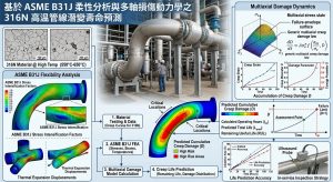
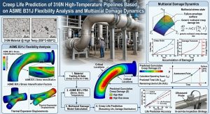
為精確量化高溫應力,本研究引入 ASME B31J 規範。該規範透過大量的有限元素分析(FEA)與實體驗證,對 SIF 與 FF 進行了深度的科學修正,使得高溫管線的巨觀柔性分析得以真實反映局部的立體應力場6。在此基礎上,本研究進一步將巨觀應力張量耦合至微觀的 Kachanov-Rabotnov 連續損傷力學模型,針對 316N 不銹鋼的特有參數,建立多尺度的潛變壽命預測框架。同時,導入相陣列超音波(PAUT)與飛時測距繞射(TOFD)非破壞檢測技術作為損傷參數的量化映射工具。最終,透過全生命週期成本(Life Cycle Cost, LCC)模型,科學性地論證「以彎代銲(高週波感應彎管)」工法在消除 HAZ 潛變弱點、延長管線壽命與大幅降低檢測成本上的實質效益。 To accurately quantify high-temperature stress, this study introduces the ASME B31J standard. Through extensive Finite Element Analysis (FEA) and empirical validation, this code provides deep scientific corrections to SIF and FF, allowing the macroscopic flexibility analysis of high-temperature piping to truly reflect the local three-dimensional stress field6. On this basis, this study further couples the macroscopic stress tensor into the microscopic Kachanov-Rabotnov continuum damage mechanics model to establish a multi-scale creep life prediction framework specific to the parameters of 316N stainless steel. Simultaneously, Phased Array Ultrasonic Testing (PAUT) and Time-of-Flight Diffraction (TOFD) non-destructive testing technologies are introduced as quantitative mapping tools for damage parameters. Finally, through a Life Cycle Cost (LCC) model, this study scientifically demonstrates the substantial benefits of the “bending-instead-of-welding (High-Frequency Induction Bending)” method in eliminating HAZ creep vulnerabilities, extending piping life, and significantly reducing inspection costs.
本文將依序從巨觀法規、微觀材料、管線設計、量化檢測與全生命週期成本等五個維度,層層遞進地梳理此一綜合性工程課題,最後輔以實務決策案例,印證本研究架構之可行性。This paper will systematically outline this comprehensive engineering subject from five dimensions: macroscopic regulations, microscopic materials, piping design, quantitative inspection, and life cycle cost, progressing layer by layer. Finally, it will be supplemented with practical decision-making case studies to verify the feasibility of this research framework.
二、 巨觀法規與應力分析:ASME B31J 規範之演進與幾何力學修正 / II. Macroscopic Regulations and Stress Analysis: Evolution of ASME B31J Standard and Geometric Mechanics Modification
要精確預測管線壽命,首要步驟是取得正確的巨觀應力邊界條件。傳統法規在處理複雜幾何構件時往往力有未逮,這促使了新一代規範的誕生。To accurately predict piping life, the first step is to obtain correct macroscopic stress boundary conditions. Traditional codes often fall short when dealing with complex geometric components, prompting the birth of a new generation of standards.
2.1 傳統 ASME B31.1 Appendix D 規範之侷限性 / 2.1 Limitations of the Traditional ASME B31.1 Appendix D Code
在傳統的管線應力分析(如 CAESAR II 或 AutoPIPE 的早期版本)中,ASME 規範利用 SIF(記為i)來放大幾何不連續處的局部名目應力,以評估疲勞壽命與熱膨脹應力。然而,舊版 Appendix D 的公式存在顯著的物理學與工程學盲區。首先,傳統公式往往僅提供單一的 SIF 數值,將平面內(In-plane)與平面外(Out-of-plane)的彎矩負載混為一談4。實際上,管件在承受平面內彎矩時,其橢圓化變形(Ovalization)與應力分佈與平面外扭曲截然不同。 In traditional piping stress analysis (such as early versions of CAESAR II or AutoPIPE), the ASME code utilizes the SIF (denoted as i) to amplify local nominal stress at geometric discontinuities to evaluate fatigue life and thermal expansion stress. However, the legacy Appendix D formulas harbor significant physics and engineering blind spots. Firstly, traditional formulas often provide only a single SIF value, conflating in-plane and out-of-plane bending moment loads4. In reality, when a piping component is subjected to an in-plane bending moment, its ovalization deformation and stress distribution are completely different from out-of-plane twisting.
其次,傳統規範在計算扭轉應力時,長期將扭轉 SIF(it)預設為 1.0,完全忽略了扭轉力矩在複雜三維管網中於三通或彎管處造成的嚴重剪應力集中8。更為致命的是,傳統模型在處理銲接三通(Welding Tee)時,將其柔性係數 k 剛性地固定為 1.0,這意味著分析軟體會將三通視為絕對剛體4。這種幾何假設導致系統中所有的熱膨脹應變都被迫由彎管來吸收,進而人為地扭曲了全局的彎矩分佈,不僅使得彎管處的應力被嚴重高估(迫使工程師增加不必要的膨脹彎與彈簧支架),同時也可能低估了三通局部的真實負載7。 Secondly, when calculating torsional stress, traditional codes have long defaulted the torsional SIF (it) to 1.0, completely ignoring the severe shear stress concentration caused by torsional moments at tees or elbows in complex three-dimensional piping networks8. Even more critically, when traditional models process welding tees, they rigidly fix the flexibility factor k at 1.0, meaning the analysis software treats the tee as an absolute rigid body4. This geometric assumption forces all thermal expansion strains in the system to be absorbed by elbows, thereby artificially distorting the global bending moment distribution. This not only severely overestimates the stress at the elbows (forcing engineers to add unnecessary expansion loops and spring hangers) but may also underestimate the true local load on the tees7.
2.2 ASME B31J 應力增強因子與柔性係數之精確化機理 / 2.2 Precision Mechanism of SIF and FF in ASME B31J
ASME B31J-2023 規範徹底改變了管線應力計算的典範,現已成為 ASME B31.1(2024 年版起)與 B31.3(2020 年版起)強制或預設的 SIF 與 FF 計算來源10。B31J 基於嚴謹的有限元素網格分析與實體應變規測試,為每種管件在三個正交方向上提供了獨立的 SIF(iin, iout, it)與柔性係數( kin, kout, kt),並分別針對主管(Run)與支管(Branch)進行解耦8。 The ASME B31J-2023 standard has completely shifted the paradigm of piping stress calculation and has now become the mandatory or default source for SIF and FF calculations for ASME B31.1 (from the 2024 edition) and B31.3 (from the 2020 edition)10. Based on rigorous finite element mesh analysis and empirical strain gauge testing, B31J provides independent SIFs (iin, iout, it) and flexibility factors (kin, kout, kt) in three orthogonal directions for each component type, decoupling them specifically for the run and branch pipes8.
在 B31J 體系中,柔性特徵值(Flexibility characteristic, h)是推導各種因子的核心幾何參數。以標準銲接三通為例,其幾何特徵值定義為:In the B31J framework, the flexibility characteristic (h) is the core geometric parameter used to derive various factors. Taking a standard welding tee as an example, its geometric characteristic is defined as:
h=4.4⋅T/r22
其中 T 為管壁厚度,r2 為平均半徑。在舊版 Appendix D 中,平面外 SIF 計算為io=0.9/h2/3,而平面內 SIF 則強制線性綁定為ii=0.75⋅io+0.25 9。B31J 則打破了此線性綁定,並提供了獨立的柔性係數公式,使得分支管的剛度矩陣得以根據實際的管徑厚度比(D/T)進行彈性縮放4。這對於外徑與厚度比(D/T)小於 100 的金屬管線系統,提供了更接近真實物理狀態的剛度重分配6。 Where T is the nominal wall thickness and r2 is the mean radius. In the legacy Appendix D, the out-of-plane SIF was calculated as io=0.9/h2/3, while the in-plane SIF was forcibly linearly bound as ii=0.75⋅io+0.25 9. B31J breaks this linear binding and provides independent flexibility factor formulas, allowing the stiffness matrix of the branch pipe to scale elastically according to the actual diameter-to-thickness ratio (D/T)4. For metallic piping systems with an outside diameter-to-thickness ratio (D/T) of less than 100, this provides a stiffness redistribution that is much closer to the true physical state6.
| 管件幾何特徵 / Component Geometric Features | B31.1 / B31.3 Appendix D 傳統評估 / Traditional Assessment | ASME B31J 現代評估與力學影響 / Modern Assessment and Mechanical Impact |
| 短半徑彎管 / Short Radius Elbow | 採用單一 i 值,保守評估彎曲應力,無方向性差異。 / Uses a single i value, conservatively evaluating bending stress without directional differentiation. | 明確區分 iin 與 iout,數值微幅降低,精確反映熱膨脹迴路中的彎矩吸收能力4。 / Clearly distinguishes iin and iout, with slightly reduced values, accurately reflecting moment absorption capacity in thermal expansion loops4. |
| 標準銲接三通 / Welding Tee | k 係數固定為 1.0(剛體假設),應力高度集中且無法釋放。 / k factor fixed at 1.0 (rigid body assumption), resulting in highly concentrated and unreleased stress. | 提供獨立且大於 1 的 k 值,有效釋放節點旋轉剛度;iin 與 iout 可降低 15% 至 40%,大幅減少支管與設備管嘴的負載7。 / Provides independent k values greater than 1, effectively releasing node rotational stiffness; iin and iout can be reduced by 15% to 40%, drastically reducing branch and equipment nozzle loads7. |
| 分支連接 / Branch Connection | 薄壁狀態(大 D/t 比)下經常低估應力集中。 / Often under-predicts stress concentration in thin-walled conditions (high D/t ratios). | 依據主管與支管壁厚比例精確縮放,對於局部剛度提供高度準確的預測,確保高溫設計安全裕度7。 / Accurately scales based on the run-to-branch thickness ratio, providing highly accurate predictions for local stiffness to ensure high-temperature design safety margins7. |
| 扭轉力矩 / Torsional Moment | 扭轉 SIF (it) 強制預設為 1.0,忽略剪應力集中。 / Torsional SIF (it) is forcibly defaulted to 1.0, ignoring shear stress concentrations. | 具體量化各管件的 it ,真實反映立體管網與不對稱熱膨脹中產生的強烈剪應力耦合效應7。 / Specifically quantifies it for each component, truly reflecting the strong shear stress coupling effects generated in 3D piping networks and asymmetric thermal expansion7. |
2.3 持續應力指標與壓力剛化效應之修正 / 2.3 Correction of Sustained Stress Index and Pressure Stiffening Effect
在處理高溫管線的自重與內部高壓等持續性負載(Sustained Loads)時,B31J 引入了更為合理的持續應力指標(Sustained Stress Index, SSI)。傳統規範常將疲勞壽命的 SIF直接套用於持續應力計算,導致設計過度保守。B31J 明確指出,塑性崩塌(Plastic collapse)的極限狀態遠不如交變疲勞破壞來得嚴苛。因此,B31J 規定持續應力的放大係數 SSI 應取為0.75i(且不得低於 1.0),這一修正大幅釋放了靜態負載下的計算應力,使工程師能夠優化管線支撐系統(如彈簧吊架與剛性支撐)的配置,降低系統整體的拘束度4。 When handling sustained loads such as self-weight and internal high pressure of high-temperature piping, B31J introduces a more reasonable Sustained Stress Index (SSI). Traditional codes often apply the fatigue life SIF directly to sustained stress calculations, leading to overly conservative designs. B31J explicitly points out that the limit state of plastic collapse is far less severe than alternating fatigue failure. Therefore, B31J specifies that the magnification factor SSI for sustained stress should be taken as 0.75i (and not less than 1.0). This correction significantly relieves the calculated stress under static loads, allowing engineers to optimize the configuration of piping support systems (such as spring hangers and rigid supports) and reduce overall system constraint4.
此外,針對大管徑且薄壁的彎管,B31J 充分引入了「壓力剛化效應」(Pressure Stiffening)。當彎管承受強大的平面內彎矩時,管壁橫截面會傾向於變扁平(即橢圓化變形),這正是彎管具備高柔性的原因。然而,當管內同時存在極高的內部蒸汽壓力時,流體壓力會極力維持管壁的圓形截面,抵抗橢圓化變形,進而降低了彎管的實際柔性。在進行高溫熱膨脹分析時,若忽略壓力剛化效應,將會高估彎管吸收熱位移的能力,導致設備端點(如汽輪機管嘴)的實際受力超出預期。導入 B31J 後,CAESAR II 能夠精準計算此一耦合效應,確保應力邊界條件的絕對安全13。 Additionally, for large-diameter and thin-walled elbows, B31J fully incorporates the “Pressure Stiffening” effect. When an elbow is subjected to a strong in-plane bending moment, the pipe wall cross-section tends to flatten (i.e., ovalization), which is the reason for the elbow’s high flexibility. However, when extremely high internal steam pressure is present simultaneously, the fluid pressure acts strongly to maintain the circular cross-section, resisting ovalization and thus reducing the actual flexibility of the elbow. If pressure stiffening is ignored during high-temperature thermal expansion analysis, the elbow’s capacity to absorb thermal displacement will be overestimated, causing the actual forces on equipment terminals (like turbine nozzles) to exceed expectations. After introducing B31J, software like CAESAR II can precisely calculate this coupling effect, ensuring the absolute safety of stress boundary conditions13.
三、 316N 沃斯田鐵不銹鋼之高溫潛變行為與微觀損傷動力學 / III. High-Temperature Creep Behavior and Microscopic Damage Dynamics of 316N Austenitic Stainless Steel
掌握了由 ASME B31J 所提供的精確巨觀應力邊界條件後,接下來必須將這些應力數據導入微觀的材料力學模型,方能真實預測管線的衰退軌跡。After mastering the accurate macroscopic stress boundary conditions provided by ASME B31J, it is imperative to input these stress data into microscopic material mechanics models to truly predict the degradation trajectory of the piping.
316N 與 316LN(低碳含氮)沃斯田鐵不銹鋼,透過在冶金過程中精確控制氮元素(Nitrogen)的添加量(通常介於 0.06 至 0.16 wt% 之間),產生了顯著的間隙固溶強化(Interstitial solid solution strengthening)效應1。氮原子的存在有效降低了材料的層錯能(Stacking fault energy),阻礙了高溫下差排(Dislocations)的攀移(Climb)與交滑移(Cross-slip)1。這種微觀機理使得 316N 在 550°C 至 650°C 的高溫環境中,不僅能維持極佳的組織穩定性,更大幅延緩了初級與次級潛變階段的變形速率,展現出卓越的長期抗潛變能力。 316N and 316LN (low carbon, nitrogen-bearing) Austenitic Stainless Steels generate a significant interstitial solid solution strengthening effect by precisely controlling the addition of nitrogen (typically between 0.06 and 0.16 wt%) during the metallurgical process1. The presence of nitrogen atoms effectively lowers the stacking fault energy of the material, hindering the climb and cross-slip of dislocations at high temperatures1. This microscopic mechanism enables 316N in a 550°C to 650°C high-temperature environment to not only maintain excellent microstructural stability but also significantly delay the deformation rate in the primary and secondary creep stages, exhibiting outstanding long-term creep resistance.
3.1 Kachanov-Rabotnov (K-R) 連續損傷力學模型 / 3.1 Kachanov-Rabotnov (K-R) Continuum Damage Mechanics Model
金屬的高溫潛變變形可分為三個階段:初級(Primary)的應變硬化階段、次級(Secondary 或 Steady-state)的穩態潛變階段,以及三級(Tertiary)的加速潛變破裂階段。在傳統工程設計中,常採用 Norton-Bailey 冪律來描述次級潛變,但該模型無法預測材料在壽命末期的加速破壞行為16。 High-temperature creep deformation of metals can be divided into three stages: the primary strain-hardening stage, the secondary (steady-state) creep stage, and the tertiary accelerated creep rupture stage. In traditional engineering design, the Norton-Bailey power law is often used to describe secondary creep, but this model cannot predict the accelerated failure behavior of the material near the end of its life16.
為了完整描繪 316N 從加載到破裂的全過程,本評估採用連續損傷力學(Continuum Damage Mechanics, CDM)領域中最核心的 Kachanov-Rabotnov (K-R) 耦合損傷模型。該模型引入了無因次損傷變數 ω(介於 0 與 1 之間,0 代表初始無損傷,1 代表巨觀裂紋萌生與破裂),將微觀的晶界孔洞(Cavities)與微裂紋生長,等效轉化為巨觀有效承載面積的下降與有效應力的增加17。 To completely depict the entire process of 316N from loading to rupture, this evaluation adopts the Kachanov-Rabotnov (K-R) coupled damage model, which is central to the field of Continuum Damage Mechanics (CDM). This model introduces a dimensionless damage variable ω (ranging from 0 to 1, where 0 represents the initial undamaged state and 1 represents macroscopic crack initiation and rupture), which equivalently transforms the growth of microscopic grain boundary cavities and microcracks into a macroscopic decrease in effective load-bearing area and an increase in effective stress17.
K-R 模型的本構微分方程式組定義如下:The constitutive differential equation system of the K-R model is defined as follows:
ε ̇cr=3/2A*(σvM/(1-ω))n-1*s/(1-ω)
ω ̇=B*σrm/(1-ω)q
在此方程式中:In these equations:
ε ̇cr 為潛變應變率張量;ε ̇cr is the creep strain rate tensor;
s 為應力偏量張量(Deviatoric stress tensor);s is the deviatoric stress tensor;
σvM 為 von Mises 等效應力;σvM is the von Mises equivalent stress;
σr 為驅動損傷演化的多軸有效應力;σr is the multiaxial effective stress driving damage evolution;
A,B,n,m,q為材料隨溫度與微觀結構變化的潛變常數19。 A,B,n,m,q are material creep constants that vary with temperature and microstructure19.
針對 316LN 與 316N 鋼材,實證研究已在 600°C 下萃取出精確的模型參數。為了量化損傷參數,研究人員透過中斷潛變試驗並量測晶界孔洞的面積分率,發現 316LN 的損傷容忍度參數(Damage tolerance factor)λ=εR/ε*(其中 εR 為破裂應變,ε* 為次級潛變率與破裂時間的乘積)約為 3.1,而損傷形狀參數 γ 約為 2419。 λ > 1 的數值特徵顯示,316N 在孔洞開始聚合進入三級潛變後,材料仍能承受相當大程度的延性變形而不會立即發生脆性斷裂,這與該材料優異的塑性變形能力相符20。 For 316LN and 316N steels, empirical studies have extracted precise model parameters at 600°C. To quantify the damage parameter, researchers conducted interrupted creep tests and measured the area fraction of grain boundary cavities, finding that the damage tolerance factor λ=εR/ε* (where εR is rupture strain and ε* is the product of secondary creep rate and rupture time) for 316LN is approximately 3.1, while the damage shape parameter γ is about 2419. The numerical characteristic of λ > 1 indicates that once the cavities begin to coalesce and enter tertiary creep, 316N can still withstand a considerable degree of ductile deformation without immediate brittle fracture, aligning with the material’s excellent plastic deformation capability20.
當導入非線性有限元素分析(如 ABAQUS 軟體中編寫 USERCREEP 子程序)時,可透過四階 Runge-Kutta 法對上述高度非線性的微分方程組進行數值積分,從而準確追蹤管線在複雜幾何(如 B31J 定義的 SIF 峰值處)的三維潛變應變累積與局部破裂軌跡16。 When imported into nonlinear finite element analysis (such as writing a USERCREEP subroutine in ABAQUS software), these highly nonlinear differential equations can be numerically integrated using the fourth-order Runge-Kutta method. This allows for accurate tracking of the three-dimensional creep strain accumulation and local rupture trajectories of the piping at complex geometries (such as SIF peaks defined by B31J)16.
3.2 Hayhurst 多軸應力函數與應力三軸度效應 / 3.2 Hayhurst Multiaxial Stress Function and Stress Triaxiality Effect
在真實的高溫管線系統中,幾何不連續處(如三通岔口、彎管內弧側)以及銲道熱影響區,其受力狀態絕非單純的單軸拉伸,而是處於高度複雜的三維多軸應力狀態22。為準確預測損傷演化速率 ω.,不能僅依賴 von Mises 應力,而必須採用 Hayhurst 等效多軸應力函數 σr: In real high-temperature piping systems, the stress states at geometric discontinuities (like tee branches, elbow intrados) and weld HAZs are by no means simple uniaxial tension, but rather highly complex three-dimensional multiaxial stress states22. To accurately predict the damage evolution rate ω., one cannot solely rely on von Mises stress; instead, the Hayhurst equivalent multiaxial stress function σr must be used:
σr=ασ1+βσvM+(1-α-β)σH
其中:Where:
σ1 為最大主應力,主要驅動晶界孔洞的成核與長大;σ1 is the maximum principal stress, primarily driving the nucleation and growth of grain boundary cavities;
σvM 為 von Mises 應力,主導晶粒內的塑性剪切變形與差排滑移;σvM is the von Mises stress, governing plastic shear deformation and dislocation slip within grains;
σH 為流體靜水壓應力,控制孔洞的體積膨脹;σH is the hydrostatic stress, controlling volumetric expansion of cavities;
α 與 β 為材料特有的多軸損傷權重係數,用以校準材料對不同應力分量的敏感度21。 α and β are material-specific multiaxial damage weight coefficients, used to calibrate the material’s sensitivity to different stress components21.
對於 316N 等延性材料,最大主應力 σ1 與應力三軸度(Stress Triaxiality, 定義為σH/σvM)對潛變損傷的加速具有決定性的影響。研究指出,當 316LN 試片帶有 V 型缺口(模擬銲縫咬邊或幾何急遽變化)時,高拘束度(High constraint)會在缺口根部引發強烈的應力三軸度,導致該區域的損傷變數 ω 急遽上升,展現出多軸應力狀態下的缺口強化或弱化效應(Notch strengthening/weakening effect)21。 For ductile materials like 316N, the maximum principal stress σ1 and stress triaxiality (defined as σH/σvM) have a decisive accelerating impact on creep damage. Studies indicate that when a 316LN specimen contains a V-notch (simulating weld undercut or abrupt geometric changes), high constraint induces strong stress triaxiality at the notch root, causing the damage variable ω in that region to rise sharply. This demonstrates a notch strengthening or weakening effect under multiaxial stress states21.
3.3 HAZ 內的 Type IV 潛變裂紋機制 / 3.3 Type IV Creep Cracking Mechanism in HAZ
在傳統銲接管線中,銲道熱影響區(HAZ)是高溫潛變壽命的致命弱點。在銲接熱循環過程中,母材經歷了極端的不均勻加熱與冷卻。特別是在細晶熱影響區(Fine-Grained HAZ, FGHAZ)與臨界區(Intercritical HAZ)中,溫度剛好達到材料的部分相變區,導致初始的奧氏體晶粒發生異常細化,且原有的強化碳氮化物(如 M23C6或碳氮化鈦/鈮)發生部分溶解與粗化24。 In traditional welded piping, the weld Heat-Affected Zone (HAZ) is the fatal weak point for high-temperature creep life. During the welding thermal cycle, the base metal undergoes extreme uneven heating and cooling. Particularly in the Fine-Grained HAZ (FGHAZ) and Intercritical HAZ, where temperatures just reach the material’s partial phase transformation zone, the initial austenite grains undergo abnormal refinement, and original strengthening carbonitrides (like M23C6 or Titanium/Niobium carbonitrides) partially dissolve and coarsen24.
這種微觀組織的劣化導致 FGHAZ 的高溫潛變強度遠低於周圍的母材與銲縫金屬。當管線系統承受由 ASME B31J 所計算出的巨觀熱膨脹彎矩與內壓時,由於母材、銲縫與 FGHAZ 三者之間的潛變變形抗力(Creep resistance)存在巨大的材料不匹配(Material mismatch),強韌的母材與銲縫會限制軟弱的 FGHAZ 發生塑性變形。這種「幾何與材料的雙重拘束」會在 FGHAZ 內部產生極高的應力三軸度(高 σH)。This microstructural degradation causes the high-temperature creep strength of the FGHAZ to be much lower than the surrounding base metal and weld metal. When the piping system bears the macroscopic thermal expansion bending moments and internal pressures calculated by ASME B31J, a massive material mismatch in creep resistance exists among the base metal, weld metal, and FGHAZ. The strong base metal and weld constrain the soft FGHAZ from plastic deformation. This “dual constraint of geometry and material” generates extremely high stress triaxiality (high σH) within the FGHAZ.
依據 Hayhurst 模型,高應力三軸度會極大地推升有效損傷應力 σr。這使得原本具備高延性的 316N 材料在 FGHAZ 處失去塑性鬆弛能力,導致晶界孔洞在低應變下即迅速成核、長大並連通,最終引發極具破壞性的巨觀微裂紋。這類發生在 FGHAZ 的低延性潛變破裂,在工程界被稱為 Type IV 裂紋(Type IV Cracking),它是導致現代高溫管線在遠低於設計壽命期內意外失效的頭號主因26。 According to the Hayhurst model, high stress triaxiality vastly elevates the effective damage stress σr. This causes the originally highly ductile 316N material to lose its plastic relaxation capability at the FGHAZ, leading grain boundary cavities to rapidly nucleate, grow, and coalesce at low strains, ultimately triggering highly destructive macroscopic microcracks. This low-ductility creep rupture occurring in the FGHAZ is known in engineering as Type IV Cracking, which is the primary cause of unexpected failures in modern high-temperature piping long before their design life ends26.
3.4 修飾型 Monkman-Grant 關係式於壽命預估之應用 / 3.4 Application of the Modified Monkman-Grant Relationship in Life Prediction
為將 K-R 模型的微觀應變率轉化為工程實用的剩餘壽命預測,可引入修飾型 Monkman-Grant (M-G) 關係式。該關係式揭示了材料次級穩態潛變率 ε ̇s 與最終破裂時間 tR 之間存在恆定的反比關係:To translate the microscopic strain rate of the K-R model into a practically useful remaining life prediction for engineering, the Modified Monkman-Grant (M-G) relationship can be introduced. This relationship reveals a constant inverse proportion between the material’s secondary steady-state creep rate ε ̇s and the final rupture time tR:
tR⋅(ε ̇s )m=C
其中 m 與 C 為取決於材料與溫度的常數。針對 316LN 鋼材在 873 K (600°C) 至 923 K (650°C) 的試驗表明,其到達 M-G 應變所需的時間與總潛變破裂壽命的比例介於 0.69 至 0.80 之間29。這意味著 316N 管線在其絕大部分的服役生命週期中,皆遵循著穩態潛變的演化規律15。 Where m and C are constants dependent on the material and temperature. Tests on 316LN steel at 873 K (600°C) to 923 K (650°C) show that the ratio of time required to reach the M-G strain to the total creep rupture life is between 0.69 and 0.8029. This implies that 316N piping follows steady-state creep evolutionary laws for the vast majority of its service life cycle15.
在實際工程評估中,工程師首先利用 ASME B31J 求出管線系統的局部最大應力,隨後將其輸入至 K-R 模型以計算出穩態潛變率 ε ̇s。最後,將此穩態應變率代入 Monkman-Grant 關係式中,即可為 316N 高溫管線建立一套純理論且具備微觀物理基礎的壽命預測基準,而無需進行耗時數萬小時的實體潛變破斷測試1。 In practical engineering assessment, engineers first use ASME B31J to find the local maximum stress of the piping system, then input it into the K-R model to calculate the steady-state creep rate ε ̇s. Finally, by substituting this steady-state strain rate into the Monkman-Grant relationship, a purely theoretical and microphysics-based life prediction baseline can be established for 316N high-temperature piping, bypassing the need for physical creep rupture tests that consume tens of thousands of hours1.
四、 管線壁厚設計與以彎代銲工法之幾何力學分析 / IV. Piping Wall Thickness Design and Geometric Mechanics Analysis of the Bending-Instead-of-Welding Method
既然銲道 HAZ 中的 Type IV 潛變裂紋是管線系統的致命弱點,且難以單靠巨觀應力釋放來完全避免,工程界勢必需要從「幾何結構一體化」的角度尋求根本解方,這正是以彎代銲工法崛起的背景。Since Type IV creep cracking in the weld HAZ is a fatal weakness of piping systems and is difficult to completely avoid solely through macroscopic stress relief, the engineering field inevitably needs to seek fundamental solutions from the perspective of “geometric structural integration.” This forms the background for the rise of the bending-instead-of-welding method.
鑑於上述威脅,大型 CCPP 電廠在主蒸汽管線設計中,開始大規模導入「以彎代銲(高週波感應彎管,High-Frequency Induction Bending)」工法。該工法藉由利用一體成型的大曲率半徑彎管取代傳統的對銲彎頭(Butt-weld elbows),徹底消除了管網中的彎頭環銲道,成為延長管線壽命的核心戰略。Given the aforementioned threats, large CCPP plants have begun large-scale implementation of the “bending-instead-of-welding (High-Frequency Induction Bending)” method in main steam piping design. By replacing traditional butt-weld elbows with integrally formed large-radius bends, this method completely eliminates the elbow circumferential welds in the piping network, serving as a core strategy to extend piping life.
4.1 內壓壁厚設計法則 (ASME B31.1 Paragraph 104.1.2) / 4.1 Internal Pressure Wall Thickness Design Rule (ASME B31.1 Paragraph 104.1.2)
在實施高週波感應彎曲前,必須精確計算並採購足夠厚度的初始直管(母管)。高溫管線的最小壁厚設計必須嚴格遵循 ASME B31.1 第 104.1.2 節之公式 (7)。承受內部設計壓力 P 的直管,其所需之最小壓力設計壁厚 t 為:Before executing high-frequency induction bending, it is essential to accurately calculate and procure initial straight pipes (mother pipes) of sufficient thickness. The minimum wall thickness design for high-temperature piping must strictly adhere to formula (7) in ASME B31.1 Paragraph 104.1.2. For a straight pipe subjected to internal design pressure P, the required minimum pressure design wall thickness t is:
t=P⋅Do/2(SE+Py)
隨後,必須加上額外的腐蝕與機械加工裕度 A,得出最小要求壁厚tm :Subsequently, additional corrosion and mechanical allowances A must be added to yield the minimum required wall thickness tm:
tm=t+A
在公式中:In the formulas:
P 為內部設計表壓力;P is the internal design gauge pressure;
Do 為管線外徑;Do is the pipe outside diameter;
SE 為材料在設計溫度下的最大容許應力與銲接接頭效率的乘積。對於 316N 無縫管,E=1.0;SE is the product of the material’s maximum allowable stress at the design temperature and the joint efficiency. For 316N seamless pipe, E=1.0 ;
y 為溫度修正係數。在極高溫環境下(例如 > 510°C),材料在管壁厚度方向的應力分佈會因潛變鬆弛而發生重分配。對於 316N,當溫度高於一定極限值時,y 值通常取 0.4 至 0.7 之間,這使得分母變大,從而在設計上反映了高溫應力重分配所帶來的厚度補償效益30。y is the temperature correction coefficient. In extremely high-temperature environments (e.g., > 510°C), stress distribution across the pipe wall thickness redistributes due to creep relaxation. For 316N, when the temperature exceeds a certain threshold, the y value is typically between 0.4 and 0.7. This increases the denominator, thereby reflecting the thickness compensation benefit brought by high-temperature stress redistribution in the design30.
4.2 感應彎管之壁厚減薄與微觀殘留應力演化 / 4.2 Wall Thinning and Microscopic Residual Stress Evolution of Induction Bends
高週波感應彎曲工法是利用感應線圈對管材進行局部窄帶加熱(通常加熱至奧氏體化溫度以上),同時施加機械推力使其彎曲。在此過程中,由於幾何變形的物理守恆,彎管的外弧側(Extrados)會承受拉伸而發生壁厚減薄,內弧側(Intrados)則因受壓而增厚33。 The high-frequency induction bending method utilizes induction coils to locally narrow-band heat the pipe material (typically above the austenitizing temperature) while simultaneously applying mechanical thrust to bend it. During this process, due to the physical conservation of geometric deformation, the extrados of the bend undergoes tension, leading to wall thinning, while the intrados thickens due to compression33.
依據 ASME B31.1 第 104.2.1 節規定,彎管在任何一點的成型後壁厚,皆不得小於該管徑所對應之直管最小要求壁厚 tm 35。因此,在採購母管時,工程師必須將外弧側的預期減薄率(通常為 10% 至 20%,視彎曲半徑 R/D 而定)以及鋼鐵廠在軋製鋼管時的負公差(Mill under-tolerance,通常為 12.5%)一併納入考量,反推計算出所需的訂購壁厚 torder 30: According to ASME B31.1 Paragraph 104.2.1, the formed wall thickness at any point on the bend shall not be less than the minimum required wall thickness tm of the corresponding straight pipe35. Therefore, when procuring mother pipes, engineers must factor in the expected thinning rate on the extrados (usually 10% to 20%, depending on the bend radius R/D) and the mill under-tolerance during steel pipe rolling (typically 12.5%), to inversely calculate the required ordering thickness torder 30:
torder=tm/[(1-外弧減薄率 )⋅(1-Mill Tolerance)]
雖然這會微幅增加初始的母管材料成本,但其帶來的一體成型結構,不僅符合流體力學中的平滑過渡(降低壓降),更在微觀殘留應力的控制上具備壓倒性優勢。Although this slightly increases the initial mother pipe material cost, the resulting integrally formed structure not only conforms to smooth transitions in fluid mechanics (lowering pressure drops) but also possesses an overwhelming advantage in controlling microscopic residual stresses.
傳統的多道次銲接過程,會在 316N 管壁厚度方向上產生高達 400 MPa 至 450 MPa 的拉伸殘留應力(Tensile residual stress)37。這些巨大的殘留應力會與運行時的高溫內壓及熱膨脹應力疊加,極大地推升了 Hayhurst 模型中的靜水壓應力 σH 與等效應力 σvM,促使損傷參數 ω 呈指數級加速攀升。 Traditional multi-pass welding processes induce tensile residual stresses as high as 400 MPa to 450 MPa across the thickness of the 316N pipe wall37. These massive residual stresses overlay with high-temperature internal operating pressures and thermal expansion stresses, drastically driving up the hydrostatic stress σH and equivalent stress σvM in the Hayhurst model, causing the damage parameter ω to climb at an exponential rate.
相對地,高週波感應彎管在完成熱彎成型後,必須依據規範進行整體的固溶退火熱處理(Solution Annealing)。對於 316N 材料,典型的固溶退火溫度介於 1040°C 至 1175°C 之間,並維持足夠的均溫時間使晶粒充分再結晶,隨後進行快速的水淬(Water quench)或強制氣冷40。此程序能產生雙重效應:第一,使加工過程中析出的碳化鉻(Chromium carbides)重新溶解入奧氏體基體中,並透過快速冷卻越過 427°C-816°C 的敏化溫度區(Sensitization zone),確保材料的耐腐蝕性;第二,徹底釋放了冷熱加工所殘留的巨觀應力,使管線恢復均勻、無應力集中的奧氏體晶粒結構40。均勻的結構徹底拔除了 Type IV 潛變裂紋的溫床,為高溫管線的長期安全提供了冶金學上的保證。 In contrast, high-frequency induction bends must undergo an overall Solution Annealing heat treatment per code requirements after hot bending is complete. For 316N material, typical solution annealing temperatures range from 1040°C to 1175°C, maintained for a sufficient soak time to allow full grain recrystallization, followed by rapid water quench or forced air cooling40. This procedure produces a dual effect: first, it redissolves chromium carbides precipitated during processing back into the austenite matrix and, via rapid cooling, bypasses the 427°C-816°C sensitization zone, ensuring the material’s corrosion resistance; second, it thoroughly releases macroscopic stresses remaining from cold/hot working, restoring the piping to a uniform, stress-free austenitic grain structure40. This uniform structure completely uproots the breeding ground for Type IV creep cracks, providing a metallurgical guarantee for the long-term safety of high-temperature piping.
五、 量化檢測之數據映射:超音波技術於潛變損傷評估之應用 / V. Quantitative Inspection Data Mapping: Application of Ultrasonic Technology in Creep Damage Assessment
儘管以彎代銲工法在新建管線中展現出優越的抗潛變潛力,但針對現役管線及系統中無法避免的局部對接銲道,工程師仍需依靠非破壞檢測(NDT)技術來捕捉早期的潛變孔洞,以驗證並修正上述的理論壽命模型。Although the bending-instead-of-welding method shows superior creep resistance potential in new piping, for active in-service piping and the unavoidable local butt welds in the system, engineers must still rely on Non-Destructive Testing (NDT) technologies to capture early creep cavities to verify and correct the theoretical life models described above.
理論預測模型必須與現場的非破壞檢測數據相互校正,方能確保壽命評估的準確度。隨著潛變損傷(孔洞與微裂紋)在管線內部的演化,材料的物理與聲學性質會發生顯著的改變。將 K-R 模型中的無因次損傷變數 ω與超音波檢測訊號建立量化的物理映射關係,是實現管線狀態監測(Condition Monitoring)與數位孿生(Digital Twin)的關鍵。Theoretical prediction models must be mutually calibrated with on-site non-destructive testing data to ensure the accuracy of life assessments. As creep damage (cavities and microcracks) evolves inside the piping, the physical and acoustic properties of the material change significantly. Establishing a quantitative physical mapping relationship between the dimensionless damage variable ω in the K-R model and ultrasonic inspection signals is key to realizing piping Condition Monitoring and Digital Twins.
5.1 沃斯田鐵不銹鋼之超音波傳播挑戰與物理映射 / 5.1 Ultrasonic Propagation Challenges and Physical Mapping of Austenitic Stainless Steel
316N 沃斯田鐵不銹鋼的銲接結構,其銲縫金屬與 HAZ 通常由粗大的柱狀晶(Columnar grains)所構成,並具有高度的聲學非等向性(Acoustic anisotropy)。這種微觀組織會導致超音波在材料內部傳播時,產生嚴重的晶界散射(Grain boundary scattering)、射束偏折(Beam steering)與模式轉換(Mode conversion)43。 In the welded structure of 316N Austenitic Stainless Steel, the weld metal and HAZ are usually composed of coarse columnar grains and exhibit a high degree of acoustic anisotropy. This microstructure causes severe grain boundary scattering, beam steering, and mode conversion when ultrasound propagates through the material43.
依據波動聲學,傳統用於碳鋼檢測的超音波橫波(Shear wave)在粗晶沃斯田鐵結構中會遭受極大的衰減(衰減率高達 6.4 dB/inch,遠大於碳鋼的 2 dB/inch),導致檢測的訊噪比(SNR)極低,幾乎無法穿透厚壁銲道43。因此,在對 316N 管線進行檢測時,必須採用較低頻率(例如 1.5 MHz 至 5 MHz)的縱波(Compression wave / Longitudinal wave)探頭,利用縱波對晶界散射較不敏感的特性,穿透厚壁管件與衰減嚴重的銲道46。 According to wave acoustics, traditional ultrasonic shear waves used for carbon steel inspection suffer immense attenuation in coarse-grained austenitic structures (attenuation rates up to 6.4 dB/inch, vastly exceeding carbon steel’s 2 dB/inch). This results in an extremely low Signal-to-Noise Ratio (SNR), rendering it nearly impossible to penetrate thick-walled welds43. Therefore, when inspecting 316N piping, it is essential to use lower frequency (e.g., 1.5 MHz to 5 MHz) longitudinal wave (compression wave) probes. By utilizing the characteristic that longitudinal waves are less sensitive to grain boundary scattering, they can penetrate thick-walled components and severely attenuating welds46.
潛變孔洞的產生,在物理上等效於材料微觀密度的下降與彈性模數的退化。超音波縱波聲速 VL 與材料力學性質的理論關係如下:The generation of creep cavities is physically equivalent to a decrease in the material’s microscopic density and degradation of the elastic modulus. The theoretical relationship between ultrasonic longitudinal wave velocity VL and material mechanical properties is as follows:
VL=√(E(1-ν)/ρ(1+ν)(1-2ν) )
其中,E 為彈性模數,ρ 為密度,ν 為柏松比46。當材料內部因為潛變累積損傷 ω 而導致有效承載截面積下降時,其表觀彈性模數 E(ω) 會隨之折減(例如 E(ω)=E0 (1-ω))。雖然孔洞同時會使材料局部密度下降,但彈性模數的退化往往佔據主導地位。因此,超音波聲速會隨著潛變損傷的累積而產生可量測的降低現象。 Where E is the elastic modulus, ρ is the density, and ν is Poisson’s ratio46. When the effective load-bearing cross-sectional area decreases due to accumulated creep damage ω inside the material, its apparent elastic modulus E(ω) will discount accordingly (e.g., E(ω)=E0 (1-ω)). Although cavities also cause the material’s local density to decrease, the degradation of the elastic modulus usually dominates. Consequently, the ultrasonic wave velocity will exhibit a measurable decrease as creep damage accumulates.
除了聲速變化,超音波衰減係數(Attenuation coefficient)對孔洞的面積分率更為敏感。研究指出,超音波衰減率的非線性變化趨勢,與 K-R 模型所定義的孔洞體積率具有高度的正相關性。透過量測管線不同位置(如直管段、彎管外弧側、銲道 HAZ)的聲速折減率(ΔV/V0)與衰減係數的變化,工程師即可利用迴歸公式反向推導出該區域目前的損傷變數 ω,實現微觀損傷的巨觀量化映射50。 In addition to velocity changes, the ultrasonic attenuation coefficient is more sensitive to the area fraction of cavities. Studies point out that the non-linear variation trend of the ultrasonic attenuation rate is highly positively correlated with the cavity volume fraction defined by the K-R model. By measuring the velocity reduction rate (ΔV/V0) and changes in the attenuation coefficient at different locations on the piping (e.g., straight pipe sections, elbow extrados, weld HAZ), engineers can use regression formulas to inversely derive the current damage variable ω in that region, realizing macroscopic quantitative mapping of microscopic damage50.
5.2 PAUT 與 TOFD 技術於高溫管線之互補應用 / 5.2 Complementary Application of PAUT and TOFD Technologies in High-Temperature Piping
為了準確捕獲三通、彎管及銲道 HAZ 內部的微小潛變孔洞與 Type IV 裂紋,現代檢測規範廣泛強制或推薦結合相陣列超音波(Phased Array Ultrasonic Testing, PAUT)與飛時測距繞射(Time-of-Flight Diffraction, TOFD)技術,兩者在檢測物理機制上具備完美的互補性:To accurately capture minute creep cavities and Type IV cracks inside tees, elbows, and weld HAZs, modern inspection codes widely mandate or recommend combining Phased Array Ultrasonic Testing (PAUT) and Time-of-Flight Diffraction (TOFD) technologies. The two possess perfect complementarity in their physical detection mechanisms:
- PAUT 扇形掃描與體積特徵定位: PAUT 利用包含數十個壓電晶片的陣列探頭,透過精確控制各晶片的激發延遲時間(Focal laws),在不移動探頭的情況下實現聲束的電子偏轉與聚焦(Beam steering and focusing)。在檢測 316N 厚壁管線時,通常使用雙基質陣列(Dual Matrix Array, DMA)縱波探頭來傳送與接收聲波,可大幅抑制粗晶噪聲並提升穿透力。PAUT 能夠直觀地顯示缺陷的體積特徵與立體位置(透過 S-Scan 扇形掃描與 C-Scan 俯視圖),特別適合用於幾何形狀複雜的 ASME B31J 應力集中熱點區域的快速大面積掃描48。PAUT Sectorial Scanning and Volumetric Feature Location: PAUT uses an array probe containing dozens of piezoelectric elements. By precisely controlling the excitation delay times (Focal laws) of each element, it achieves electronic beam steering and focusing without moving the probe. When inspecting 316N thick-walled piping, Dual Matrix Array (DMA) longitudinal wave probes are typically used for transmitting and receiving sound waves, greatly suppressing coarse-grain noise and enhancing penetrability. PAUT can intuitively display the volumetric features and 3D locations of flaws (via S-Scan sectorial scans and C-Scan top views), making it particularly suitable for rapid, large-area scanning of complex geometric hot spots with stress concentrations defined by ASME B31J48.
- TOFD 繞射測距與精密尺寸量化: TOFD 不依賴傳統超音波的缺陷反射振幅(Amplitude-based),而是利用一對發射與接收探頭,捕捉聲波撞擊裂紋上下尖端時所產生的微弱繞射波(Diffracted waves)。由於繞射信號到達接收端的時間差(Time of flight)完全取決於聲波傳播的路徑幾何,TOFD 對於潛變微裂紋(尤其是與表面垂直的 Type IV 裂紋)具有無與倫比的測高精度(垂直深度誤差通常在 ±5 mm 以內)53。TOFD Diffraction Ranging and Precise Size Quantification: TOFD does not rely on traditional ultrasonic defect reflection amplitude (amplitude-based) but rather uses a pair of transmitting and receiving probes to capture the weak diffracted waves generated when sound waves strike the top and bottom tips of a crack. Since the time difference (Time of flight) for diffracted signals to reach the receiver depends entirely on the path geometry of the propagating sound waves, TOFD has unparalleled height-measurement accuracy for creep microcracks (especially Type IV cracks growing perpendicular to the surface), with vertical depth errors typically within ±0.5 mm53.
在工程實務中,檢測流程通常由 PAUT 進行全區掃描,快速定位出疑似缺陷的區域,並彌補 TOFD 在近表面存在的盲區(Dead zones)缺陷;隨後,再由 TOFD 針對檢出之潛變微裂紋進行高精度的絕對尺寸定標(Defect sizing)54。 In engineering practice, the inspection workflow usually begins with PAUT performing full-area scanning to quickly locate suspected defect areas and compensate for the near-surface dead zones inherent in TOFD. Subsequently, TOFD is used to conduct highly accurate absolute defect sizing on the detected creep microcracks54.
將 TOFD 精確測得的裂紋尺寸 α,代入斷裂力學的應力強度因子模型中,再結合 ASME B31J 算出的局部實際應力(包含內壓與熱膨脹力矩),即可計算出裂紋的擴展速率,進而對管線剩餘壽命進行精密的定量評估,徹底取代過去依賴經驗法則的模糊判斷。
By substituting the crack size α precisely measured by TOFD into a fracture mechanics Stress Intensity Factor model, and combining it with the actual local stress calculated by ASME B31J (including internal pressure and thermal expansion moments), the crack propagation rate can be calculated. This enables a precise quantitative evaluation of the piping’s remaining life, completely replacing the vague judgments of the past that relied on rules of thumb.
六、 全生命週期成本 (LCC) 與以彎代銲工法之效益評估 / VI. Life Cycle Cost (LCC) and Cost-Benefit Evaluation of the Bending-Instead-of-Welding Method
當 NDT 檢測技術能精準量化潛變損傷後,其背後隱含的是對整體營運策略的影響。這促使我們將視角從單一技術層面,拉高至整座電廠的全生命週期成本(LCC)評估。
When NDT inspection technology can precisely quantify creep damage, it implicitly affects overall operational strategy. This compels us to elevate our perspective from the single-technology level to the Life Cycle Cost (LCC) evaluation of the entire power plant.
對於大型 CCPP 電廠而言,主蒸汽與高溫給水管線是資本支出龐大且維護成本高昂的關鍵系統。由於銲道 HAZ 粗大的柱狀晶結構大幅增加了 PAUT/TOFD 的檢測難度與時間成本,評估導入「以彎代銲」工法的經濟效益,必須跳脫單純的材料採購思維,採用 LCC 模型進行宏觀量化。For large CCPP plants, main steam and high-temperature feedwater piping are critical systems involving massive capital expenditures and high maintenance costs. Since the coarse columnar grain structure of the weld HAZ drastically increases the difficulty and time costs of PAUT/TOFD inspections, evaluating the economic benefits of introducing the “bending-instead-of-welding” method must break free from simple material-procurement thinking and adopt an LCC model for macroscopic quantification.
LCC 評估模型可表示為:The LCC evaluation model can be expressed as:
LCC=Cic (“初始建置成本” )+Ce (“營運與能源成本” )+Cm (“檢測與維護成本” )
LCC=Cic (Initial Construction Cost)+Ce (Operation and Energy Cost )+Cm (Inspection and Maintenance Cost)59。
針對大型 CCPP 電廠的高溫管網進行深度比較分析如下: An in-depth comparative analysis for the high-temperature piping networks of large CCPP plants is as follows:
6.1 初始建置成本 (Cic) 的轉移與優化 / 6.1 Shift and Optimization of Initial Construction Costs (Cic)
採用以彎代銲工法,感應彎管的單價確實高於標準的對銲彎頭(Butt-weld elbows),且為了補償外弧減薄,必須採購更厚、更昂貴的無縫母管。然而,一體成型的長管段大幅減少了現場高溫銲接的接頭數量。這直接省去了龐大的高階銲工薪資、特殊銲材消耗、耗時的銲前預熱與銲後熱處理(PWHT)費用,以及銲接完成後的初始射線檢測(RT)或 PAUT 費用。此外,結合 ASME B31J 提供的精確柔性係數 k,設計者可利用感應彎管客製化大曲率半徑(如R=3D 或 5D)的優勢,顯著降低管網系統的總體剛性。這使得工程師能減少昂貴的恆力彈簧吊架(Constant spring hangers)與抗震拉桿的安裝數量7。綜合評估下,其初始建置成本通常持平,甚至在管網複雜度較高的區域呈現下降趨勢。 By adopting the bending-instead-of-welding method, the unit price of induction bends is indeed higher than standard butt-weld elbows, and thicker, more expensive seamless mother pipes must be purchased to compensate for extrados thinning. However, the integrally formed long pipe sections drastically reduce the number of on-site high-temperature weld joints. This directly eliminates substantial costs for high-level welders’ salaries, special welding consumables, time-consuming preheating and Post-Weld Heat Treatment (PWHT), as well as initial Radiographic Testing (RT) or PAUT after welding. Furthermore, combining the accurate flexibility factor k provided by ASME B31J, designers can leverage the advantage of induction bends custom-made with large bend radii (e.g., R=3D or 5D) to significantly lower the overall rigidity of the piping system. This allows engineers to reduce the number of expensive constant spring hangers and sway struts7. Under a comprehensive assessment, the initial construction costs usually break even, and may even show a downward trend in areas with highly complex piping networks.
6.2 營運與能源成本 (Ce) 的微幅改善 / 6.2 Marginal Improvement in Operation and Energy Costs (Ce)
傳統銲接彎頭在銲道根部常存在銲瘤或幾何不連續,容易產生局部紊流。感應彎管具有完美的平滑內部流道過渡,可減少管內高壓蒸汽的摩擦壓降。在電廠三十年的連續運行下,這有助於微幅降低鍋爐給水泵浦或蒸汽壓縮系統的能源消耗,提升整體熱效率59。 Traditional welded elbows often have weld protrusions or geometric discontinuities at the weld root, easily causing local turbulence. Induction bends possess a perfectly smooth internal flow transition, reducing friction pressure drops for the high-pressure steam inside the pipe. Over a power plant’s continuous thirty-year operation, this helps marginally reduce the energy consumption of boiler feedwater pumps or steam compression systems, enhancing overall thermal efficiency59.
6.3 檢測與維護成本 (Cm) 的顛覆性降低(核心效益) / 6.3 Disruptive Reduction in Inspection and Maintenance Costs (Cm) (Core Benefit)
在電廠 30 至 40 年的運行週期內,高溫管線需面臨嚴苛且頻繁的法規強制檢測(In-service Inspection, ISI)。傳統管線擁有大量彎頭與直管對接的環銲道,每個銲道皆是法規要求 100% 體積檢測(如 PAUT/TOFD)的必檢熱點。消除這些彎頭銲道,意味著直接砍掉相應的 NDT 檢測預算、高空搭架成本以及昂貴的保溫層(Insulation)拆裝與修復費用。更關鍵的是,消除了 HAZ 即消除了 Type IV 潛變失效的定時炸彈。這從根本上避免了因突發性管線破裂或微裂紋擴展過快所導致的非計畫性停機(Unplanned downtime)損失。對於 CCPP 電廠而言,停機一天的營業損失與重置成本極為驚人。以彎代銲工法透過冶金結構的本質安全,將後期的Cm 壓縮至最低,使得 LCC 呈現極為優異的投資報酬率。During a power plant’s 30 to 40-year operating cycle, high-temperature piping faces rigorous and frequent mandatory In-service Inspections (ISI) by codes. Traditional piping has numerous circumferential welds connecting elbows and straight pipes, each being a mandatory hot spot requiring 100% volumetric inspection (e.g., PAUT/TOFD). Eliminating these elbow welds means directly cutting the corresponding NDT inspection budgets, high-altitude scaffolding costs, and the expensive removal and repair of insulation. More critically, eliminating the HAZ means removing the ticking time bomb of Type IV creep failure. This fundamentally avoids losses from unplanned downtime caused by sudden pipe ruptures or excessively rapid microcrack propagation. For CCPP plants, the operational losses and replacement costs of a single day of downtime are staggering. By ensuring intrinsic safety in the metallurgical structure, the bending-instead-of-welding method compresses the subsequent Cm to an absolute minimum, allowing the LCC to show a highly exceptional return on investment.
七、 實務工程與決策最佳化:316N 與 316LN 沃斯田鐵不銹鋼冷彎管線導入實例 / VII. Practical Engineering and Decision Optimization: Implementation Examples of 316N and 316LN Austenitic Stainless Steel Cold-Bent Piping
LCC 模型從理論與宏觀財務角度肯定了以彎代銲的優勢;而落實到真實的專案執行中,業主、設計方與施工單位的實務決策,則為這些理論效益提供了具體的驗證場域。The LCC model affirms the advantages of bending instead of welding from theoretical and macroscopic financial perspectives; while in actual project execution, the practical decisions made by owners, designers, and construction contractors provide a concrete validation arena for these theoretical benefits.
7.1 業主營運決策:3D/5D 彎徑替代傳統 1.5D 彎頭銲道之維護管理 / 7.1 Owner’s Operational Decision: Maintenance Management of Substituting 3D/5D Bend Radii for Traditional 1.5D Elbow Welds
對於發電廠與石化廠的業主而言,決定選用 3D 或 5D 大彎曲半徑的 316N/316LN 沃斯田鐵不銹鋼冷彎管線來取代傳統的 1.5D 彎頭銲道,是一項從源頭改變全生命週期成本的戰略性決策。傳統 1.5D 銲接彎頭不僅應力集中程度較高,其熱影響區更是潛變損傷與疲勞裂紋的高發區域。透過導入 3D/5D 彎管,業主徹底消除了彎頭兩側的銲道,此舉能大幅降低營運期間的維護停機時間與後續昂貴的 NDT 檢測預算。同時,3D/5D 彎管平滑的流道過渡,相較於 1.5D 彎頭能更有效減少管內高溫流體的紊流與摩擦壓降,長期運行下對提升整體系統的能源效率亦有顯著助益。For owners of power plants and petrochemical plants, deciding to use 3D or 5D large-bend-radius 316N/316LN austenitic stainless steel cold-bent piping to replace traditional 1.5D elbow welds is a strategic decision that alters life cycle costs at the source. Traditional 1.5D welded elbows not only have a higher degree of stress concentration, but their heat-affected zones are also high-incidence areas for creep damage and fatigue cracks. By introducing 3D/5D bends, owners completely eliminate the welds on both sides of the elbows. This action can drastically reduce maintenance downtime during operation and subsequent expensive NDT inspection budgets. At the same time, the smooth flow transition of 3D/5D bends can more effectively reduce turbulence and friction pressure drop for the high-temperature fluid inside the pipes compared to 1.5D elbows, offering significant long-term operational benefits to overall system energy efficiency.
7.2 EPC 承包商設計單位:1.5D/3D/5D 彎徑之空間排列與實務考量 / 7.2 EPC Contractor Design Units: Spatial Arrangement and Practical Considerations for 1.5D/3D/5D Bend Radii
從 EPC 承包商的管線設計角度出發,利用 ASME B31J 規範進行柔性分析時,3D 與 5D 彎管展現出遠優於傳統 1.5D 銲接彎頭的柔性特徵,其較低的應力增強因子能有效吸收系統的熱膨脹應變。這種高柔性使設計單位得以減少系統中減震支撐的設置數量,優化整體受力狀態。然而,在實務的空間配置上,3D/5D 彎管需要較大的空間足跡(Spatial footprint)。因此,設計單位在 3D 配管佈局時必須採取平衡策略:在主要熱膨脹迴路、長距離管廊與應力集中區,優先佈置 3D 或 5D 彎管以最大化釋放應力;而在設備管嘴周圍或高度擁擠的機組內部,受限於嚴苛的幾何干涉,則需維持選用空間佔用最小的 1.5D 彎管32。 From the perspective of an EPC contractor’s piping design, when utilizing the ASME B31J code for flexibility analysis, 3D and 5D bends exhibit flexibility characteristics vastly superior to traditional 1.5D welded elbows, and their lower stress intensification factors can effectively absorb the system’s thermal expansion strains. This high flexibility allows design units to reduce the number of shock-absorbing supports installed in the system, optimizing the overall stress state. However, in practical spatial configuration, 3D/5D bends require a larger spatial footprint. Therefore, design units must adopt a balancing strategy during 3D piping layout: prioritizing the arrangement of 3D or 5D bends in main thermal expansion loops, long-distance pipe racks, and stress-concentrated areas to maximize stress release; while around equipment nozzles or inside highly congested unit interiors, constrained by severe geometric interference, they must maintain the use of 1.5D bends that occupy the least amount of space32.
7.3 潁璋工程之三合一工法:冷作彎管應用於非常規化傾斜角之實務效益 / 7.3 Ying Zhang Engineering’s Three-in-One Method: Practical Benefits of Cold Bending Applied to Unconventional Inclination Angles
在國內的工程實務中,針對 316N 與 316LN 等高應變合金鋼管線,潁璋工程成功導入了涵蓋「冷作彎管 + 高週波局部熱處理 (IH-PBHT) + 數位履歷 QR Code」的三合一技術工法60。在複雜的石化管線對接(Tie-in)或電廠狹窄空間中,管線往往需要以「非常規化傾斜角」進行立體轉向,傳統標準配件難以完美契合。利用客製化機台進行 3D 與 5D 彎徑的精準冷作彎曲,完美克服了特殊角度的空間幾何限制。此工法最實質的效益在於大幅降低了現場的銲接施工工序,並等比減少了高昂的非破壞檢測數量;配合後續的熱處理程序恢復金相組織後,不僅確保了材料在高溫下的抗潛變能力,更將整體專案的時間成本極度壓縮,達成專案總體成本的最佳化目標4。 In domestic engineering practice, for high-strain alloy steel piping such as 316N and 316LN, Ying Zhang Engineering has successfully introduced a three-in-one technical method comprising “Cold Bending + High-Frequency Induction Local Heat Treatment (IH-PBHT) + Digital Resume QR Code”60. In complex petrochemical tie-ins or narrow power plant spaces, piping often needs to make three-dimensional turns at “unconventional inclination angles,” which traditional standard fittings struggle to match perfectly. Using customized machines for precise cold bending with 3D and 5D radii perfectly overcomes spatial geometric limitations at special angles. The most substantial benefit of this method is the drastic reduction of on-site welding procedures and the proportional decrease in the massive volume of costly non-destructive testing. By coordinating with subsequent heat treatment procedures to restore the metallographic structure, it not only guarantees the material’s creep resistance at high temperatures but also extremely compresses the overall project time cost, achieving the goal of optimizing total project costs4.
八、 結論 / VIII. Conclusion
本研究深度整合了 ASME B31J 巨觀法規、K-R 連續損傷力學、超音波非破壞檢測物理學以及全生命週期經濟學,針對 CCPP 電廠 316N 高溫管線之潛變壽命與以彎代銲工法,得出以下核心結論:This study deeply integrates ASME B31J macroscopic regulations, K-R continuum damage mechanics, ultrasonic non-destructive testing physics, and life cycle economics. Concerning the creep life of 316N high-temperature piping in CCPP plants and the bending-instead-of-welding method, the following core conclusions are drawn:
- 應力分析範式的全面升級 / Comprehensive Upgrade of Stress Analysis Paradigm: 強烈建議在高溫管線設計中揚棄傳統保守且具物理盲區的1/B31.3 Appendix D 估算方法。導入 ASME B31J 進行柔性分析,利用其在三個正交方向上獨立的 SIF 與 FF,並校正壓力剛化效應與持續應力指標(SSI),能精確捕捉三通與彎管的真實應力集中狀態,為後續的微觀損傷力學計算提供準確的巨觀三維應力張量邊界條件。It is strongly recommended to abandon the traditionally conservative B31.1/B31.3 Appendix D estimation methods, which have physical blind spots, in high-temperature piping design. Introducing ASME B31J for flexibility analysis, utilizing its independent SIF and FF in three orthogonal directions, and correcting for pressure stiffening effects and the Sustained Stress Index (SSI), can precisely capture the true stress concentration states of tees and elbows, providing accurate macroscopic three-dimensional stress tensor boundary conditions for subsequent microscopic damage mechanics calculations.
- 多尺度潛變壽命預測框架的實用化 / Practical Application of Multi-Scale Creep Life Prediction Framework: 316N 不銹鋼的壽命預估不能僅依賴名目應力與線性疲勞累積。必須運用 Kachanov-Rabotnov (K-R) 耦合損傷模型與 Hayhurst 多軸應力函數,將最大主應力與應力三軸度納入考量,針對幾何複雜處與高拘束區進行數值積分,並結合 Monkman-Grant 關係式,方能真實且具物理意義地預測材料從穩態潛變進入三級加速階段的臨界點與最終破裂時間。Life estimation for 316N stainless steel cannot rely solely on nominal stress and linear fatigue accumulation. The Kachanov-Rabotnov (K-R) coupled damage model and the Hayhurst multiaxial stress function must be applied to take into account maximum principal stress and stress triaxiality. By performing numerical integration for geometrically complex locations and high-constraint zones, and combining this with the Monkman-Grant relationship, one can truly and physically predict the critical point when the material transitions from steady-state creep into the tertiary acceleration stage, as well as its final rupture time.
- 先進超音波量化映射的現場實踐 / On-Site Practice of Advanced Ultrasonic Quantitative Mapping: 針對潛變損傷的實體監控,必須克服 316N 粗晶組織的衰減挑戰,採用低頻 DMA 探頭進行縱波 PAUT 掃描,搭配 TOFD 技術進行裂紋精密定標。TOFD 能對 Type IV 潛變微裂紋提供毫米級精度的深度量測;而量測所得的超音波衰減係數與聲速折減,可直接映射至 K-R 模型中的損傷變數 ω,實現理論壽命預測與現場 NDT 檢測數據的閉環校正。For the physical monitoring of creep damage, the attenuation challenges of the 316N coarse-grain structure must be overcome by employing low-frequency DMA probes for longitudinal wave PAUT scanning, coupled with TOFD technology for precise crack sizing. TOFD can provide depth measurements with millimeter-level accuracy for Type IV creep microcracks; meanwhile, the measured ultrasonic attenuation coefficients and velocity reductions can be mapped directly to the damage variable ω in the K-R model, realizing closed-loop calibration between theoretical life predictions and on-site NDT inspection data.
- 以彎代銲工法之戰略與經濟價值 / Strategic and Economic Value of the Bending-Instead-of-Welding Method: 高週波感應彎管不僅是製造工法的改變,更是消滅 HAZ 潛變裂紋風險的核心戰略。在遵循 ASME B31.1 嚴謹的壁厚減薄計算與高溫固溶退火把關下,以彎代銲工法徹底消除了彎頭兩側的粗晶銲縫與殘留應力。從全生命週期成本(LCC)的角度來看,此舉將後續數十年的 PAUT/TOFD 檢測維護成本降至最低,並確保了電廠高溫蒸汽系統的絕對本質安全性與最佳化工廠經濟效益。High-frequency induction bending is not merely a change in manufacturing methods, but a core strategy to eliminate the risk of HAZ creep cracks. Under the strict gates of ASME B31.1 wall-thinning calculations and high-temperature solution annealing, the bending-instead-of-welding method thoroughly eliminates the coarse-grain welds and residual stresses on both sides of the elbows. From the perspective of Life Cycle Cost (LCC), this reduces PAUT/TOFD inspection and maintenance costs for the ensuing decades to an absolute minimum, ensuring absolute intrinsic safety for the plant’s high-temperature steam systems and optimizing the plant’s economic benefits.
參考文獻 / References
- Creep deformation and constitutive modelling of 316LN SS with, https://www.researchgate.net/publication/374172370_Creep_deformation_and_constitutive_modelling_of_316LN_SS_with_varying_nitrogen_content
- Experimental Evaluation of Temperature and Strain-Rate, https://www.preprints.org/manuscript/202412.2165
- Creep-Fatigue and Fatigue Crack Growth Properties of 316 LN, https://repository.lib.ncsu.edu/bitstreams/fc7fa23d-664f-4b24-8d14-cec0c73275cd/download
- Mastering ASME B31J Piping Stress Analysis for Plant Integrity, https://epcland.com/asme-b31j-piping-stress-analysis/
- Effect of B31J SIF (i) and Flexibility Factors (k) on Pipe Stress, https://www.researchgate.net/publication/398298757_Effect_of_B31J_SIF_i_and_Flexibility_Factors_k_on_Pipe_Stress_Analysis_Compared_to_Appendix_D_Values
- ASME B31J: I & K Factors in Pipe Analysis, https://www.cortexsoftware.com.au/blog/understanding-asme-b31j-methods-i-factors-and-k-factors-in-piping-stress-analysis
- ASME B31J-2023 Overview: Stress Intensification Factor (SIF) and, https://fengshecad.com/795/
- Stress Intensity Factor (SIF), Flexibility Factor: ASME B31.3 vs ASME, https://whatispiping.com/stress-intensity-factor-sif-flexibility-factor-asme-b-31j/
- Welding Tee SIF Calculator — ASME B31.3 Appendix D / B31J, https://pipingtoolset.com/calculators/welding-tee-sif/
- SIF & Flexibility Factors — ASME B31J-2023 & NM.1 HDPE, https://pipingtoolset.com/tools/sif-flexibility-factors/
- ASME B31J (2023) Stress Intensification Factors, https://docs.bentley.com/LiveContent/web/AutoPIPE-v2026/Help/en/Topics/Codes/ASME_B31J_2023_Stress_Intensification_Factors.html
- Sustained Stress Indices (SSI) in The B31.3 2010 Edition – Scribd, https://www.scribd.com/document/372066988/Sustained-Stress-Indices-SSI-in-the-B31-3-2010-Edition
- ASME B31J B31J Essentials Why These Are Useful in Piping Stress, https://www.scribd.com/document/648213385/whatispiping-com-ASME-B31J-B31J-Essentials-Why-these-are-useful-in-Piping-Stress-Analysis
- CAESAR II® – Hexagon PPM – PDF Catalogs – DirectIndustry, https://pdf.directindustry.com/pdf/hexagon-ppm/caesar-ii/123785-580226.html
- TENSILE AND CREEP DATA OF 316L (N) STAINLESS STEEL, http://www.arpnjournals.com/jeas/research_papers/rp_2014/jeas_0514_1091.pdf
- New Creep Crack Growth Prediction Model for the Life Assessment, https://www.mdpi.com/2075-4701/13/11/1854
- Curve Fitting for Damage Evolution through Regression Analysis for, https://www.mdpi.com/1996-1944/14/19/5518
- Mathematical analysis of fully coupled approach to creep damage, https://arxiv.org/pdf/math-ph/0601052
- Creep characterization of type 316LN and HT-9 stainless steels by, https://www.researchgate.net/publication/251229823_Creep_characterization_of_type_316LN_and_HT-9_stainless_steels_by_the_K-R_creep_damage_model
- Creep characterization of type 316LN and HT-9 stainless steels by, https://www.osti.gov/etdeweb/biblio/20667516
- Prediction of Creep Behaviour of 316LN SS Under Uniaxial and, https://www.researchgate.net/publication/340418793_Prediction_of_Creep_Behaviour_of_316LN_SS_Under_Uniaxial_and_Multiaxial_Stress_State_Using_Kachanov-Rabotnov_Model_at_923_K
- Development of constitutive equations for creep damage behaviour, https://www.witpress.com/Secure/elibrary/papers/DM00/DM00041FU.pdf
- (PDF) Study on creep damage and life prediction of threaded, https://www.researchgate.net/publication/292345913_Study_on_creep_damage_and_life_prediction_of_threaded_connections_at_high_temperature
- Location of type IV fracture. – ResearchGate, https://www.researchgate.net/figure/Location-of-type-IV-fracture_fig3_305623058
- Factors affecting Type IV creep damage in Grade 91 steel welds, https://www.researchgate.net/publication/257340149_Factors_affecting_Type_IV_creep_damage_in_Grade_91_steel_welds
- Effect of stress triaxiality on the creep ductility: (a) pipe and rotor, https://www.researchgate.net/figure/Effect-of-stress-triaxiality-on-the-creep-ductility-a-pipe-and-rotor-steels-under_fig8_260800426
- Type IV Cracking of Weldments in Enhanced Ferritic Steels – TWI, https://www.twi-global.com/technical-knowledge/published-papers/review-of-type-iv-cracking-of-weldments-in-9-12cr-creep-strength-enhanced-ferritic-steels/
- Improving creep strength of the fine-grained heat-affected zone of, http://ijmmm.ustb.edu.cn/cn/article/pdf/preview/10.1007/s12613-023-2760-0.pdf
- Creep behavior of nuclear grade 316LN austenitic stainless steel at, https://www.researchgate.net/publication/351745733_Creep_behavior_of_nuclear_grade_316LN_austenitic_stainless_steel_at_873_K_and_923_K
- ASME B31.1 Wall Thickness Calculator — ¶104.1.2 – Piping Toolset, https://pipingtoolset.com/calculators/b311-pipe-wall-thickness/
- ASME B31.1 Minimum Wall Thickness Guide | PDF – Scribd, https://www.scribd.com/document/944455647/ASME-B31-translated
- ASME B31.1 Pressure Design Explained: Pipe Thickness, https://mypipingnotes.com/asme-b31-1-pressure-design/
- ASME B31.1 Pipe Bend Calculators – Pipeng Toolbox, http://pipeng.com/index.php/ts/itdmotdiam006l/
- ASME B31.3 Processing Piping – Required Pressure Design Wall, https://www.maplesoft.com/applications/download.aspx?id=154848/RequiredPressureDesignWallThicknessforBendsASMEB31.3.flow.pdf
- ASME-B31.1.pdf – Future Energy Steel, https://energy-steel.com/wp-content/uploads/2025/03/ASME-B31.1.pdf
- ANSI/ASME B31.1, “Power Piping” American National Standard, https://www.nrc.gov/docs/ML0314/ML031470592.pdf
- Characterization of Residual Stress and Plastic Strain in Austenitic, https://oro.open.ac.uk/61483/1/13835622.pdf
- Effect of Process Parameters on Welding Residual Stress of 316L, https://pubmed.ncbi.nlm.nih.gov/38793269
- Prediction of Residual Stresses in 316 Stainless Steel Pipes Welded, https://www.researchgate.net/publication/412859274_Prediction_of_Residual_Stresses_in_316_Stainless_Steel_Pipes_Welded_Joint
- Heat Treatment of 316 1.4401 316L 1.4404 Stainless Steel, https://tubingchina.com/316-Heat-Treatment.htm
- Solution Annealing Austenitic Stainless Steel (304, 316), https://resources.utec.co/ht-stainless-steel/solution-annealing-austenitic-stainless/
- Influence of 40% Cold Working and Annealing on Precipitation in, https://pmc.ncbi.nlm.nih.gov/articles/PMC9505488/
- High Frequency Inspection Solution for Austenitic Stainless-Steel, https://www.cinde.ca/download.php?/conference/presentations/Rioux_2018135-HighFreqSolutionStainlessSteel_CINDE.pdf
- Influencing Parameters for Ultrasonic Inspection of Austenitic Welds, https://www.twi-global.com/media-and-events/insights/influencing-parameters-for-ultrasonic-inspection-of-austenitic-welds
- Ultrasonic Testing of Stainless Steel Welds | PDF – Scribd, https://www.scribd.com/document/577750805/Ultrasonic-Testing-of-Austenitic-Stainless-Steel-Welds
- Ultrasonic Testing — Technique, Calibration, Acceptance, https://atlantisndt.com/blog/ultrasonic-testing-ultimate-guide
- (PDF) On Qualification of TOFD Technique for Austenitic Stainless, https://www.researchgate.net/publication/345033710_On_Qualification_of_TOFD_Technique_for_Austenitic_Stainless_Steel_Welds_Inspection
- How to Implement Phased Array Inspections for Stainless Steel Welds, https://blog.eddyfi.com/en/how-to-implement-phased-array-inspections-for-stainless-steel-welds
- Ultrasonic Inspection Formulas – NDE-Ed.org, https://www.nde-ed.org/NDETechniques/Ultrasonics/ultrasonicFormula.xhtml
- Ultrasonic evaluation of creep damage in steel – ResearchGate, https://www.researchgate.net/publication/256367726_Ultrasonic_evaluation_of_creep_damage_in_steel
- Detection of Creep Damage by Ultrasonics, https://dr.lib.iastate.edu/bitstreams/da23d1e1-4da4-44eb-9650-4848eb7f01c5/download
- Creep Tests and Fractional Creep Damage Model of Saturated, https://www.mdpi.com/2073-4441/17/16/2492
- PAUT vs TOFD: Key Differences Explained – OnestopNDT, https://www.onestopndt.com/ndt-articles/paut-vs-tofd-ultrasonic-testing-guide
- Advanced Ultrasonic Testing: PAUT & TOFD – OnestopNDT, https://www.onestopndt.com/ndt-articles/advanced-ultrasonic-testing-phased-array-tofd
- Phased Array Ultrasonic Testing of Austenitic Stainless Steel Welds, https://repository.cern/records/ws0f8-6mn22/files/CERN-THESIS-2018-124.pdf?download=1
- Time of Flight Diffraction (TOFD): Complete Guide – Singapore, https://www.sndt.com.sg/time-of-flight-diffraction-tofd-complete-guide/
- TOFD: Overview and Applications | PDF | Analog To Digital Converter, https://www.scribd.com/document/369040432/318491070-TOFD-Full-Notes-pdf
- Advanced Ultrasonic Testing Methods: TOFD, Guided Waves, https://scanndt.com/advanced-ultrasonic-testing-methods-tofd-guided-waves-hybrid-techniques/
- Pipeline Pump Life-Cycle Cost (LCC) Calculator – BBP, https://bbpmfg.com/booster-pipeline-pumps/pipeline-pump/pipeline-pump-life-cycle-cost-lcc-calculator/
- 潁璋工程興業有限公司– 冷作彎管, https://yz-pipe-bending.com.tw/