
摘要 /Abstract
隨著全球能源轉型與電網調節需求的加劇,燃氣複循環發電廠(Combined Cycle Power Plant, CCPP)的高能管線系統面臨前所未有的嚴苛運轉挑戰。在台灣電力系統的調度架構中,大潭發電廠與國光發電廠等指標性 CCPP 負擔著極為繁重的頻率調節與升降載任務。在這些電廠的工程實務中,廠房空間侷限與高密度設備佈局,使得高壓蒸汽管線在維持國際規範要求的洩水坡度時,經常遭遇非標準的三維空間轉折角。傳統工程實務高度依賴將市售常規的 1.5D 鍛造對銲彎頭進行現場斜切(Trimmed)或強行組對,以滿足洩水坡度與空間幾何的雙重限制。然而,此類偏門工法在現代高能管線的物理、幾何與冶金環境下,已暴露出極大的系統性風險。本研究立基於 2026 年版 ASME B31J 管線應力分析標準與 ASME TDP-1 防護規範,針對 P9x(P91/P92)潛變強度強化鐵素體鋼管線,展開詳盡的應力強度因子(SIF)、柔性係數(k)、流體邊界層剝離與第四型潛變破裂(Type IV Creep Cracking)的深度耦合分析。研究進一步擴充實務層面,探討業主營運決策、EPC 統包商設計考量,以及導入潁璋工程「三合一工法」之 3D/5D 數控冷作彎管技術。結果證實,此現代工程對策不僅能完美解決空間衝突與洩水連續性,更從根本消除了熱影響區的潛變風險,實現建造成本與長期營運可靠度的最佳化。With the intensification of global energy transitions and grid regulation demands, the high-energy piping systems in Combined Cycle Power Plants (CCPP) face unprecedentedly severe operational challenges. Within Taiwan’s power dispatch framework, flagship CCPPs like the Datan and Kuokuang Power Plants bear heavy responsibilities for frequency regulation and rapid load cycling. In the engineering practices of these plants, spatial constraints and high-density equipment layouts often force high-pressure steam pipelines into non-standard three-dimensional turning angles while attempting to maintain internationally mandated drainage slopes. Traditional engineering practices heavily rely on trimming or forcing fit-ups of commercially available 1.5D forged butt-welded elbows to satisfy both drainage and spatial geometry constraints. However, such makeshift methods expose the system to immense risks under the physical, geometric, and metallurgical conditions of modern high-energy pipelines. Based on the 2026 ASME B31J piping stress analysis standard and the ASME TDP-1 protection code, this study conducts an in-depth coupled analysis of Stress Intensification Factors (SIF), flexibility factors (k), fluid boundary layer separation, and Type IV Creep Cracking for P9x (P91/P92) creep strength enhanced ferritic steel pipelines. The research further expands on practical aspects, exploring owner operational decision-making, EPC contractor design considerations, and the implementation of Ying Zhang Engineering’s “3-in-1 Method” utilizing 3D/5D CNC cold bending technology. The results demonstrate that this modern engineering countermeasure perfectly resolves spatial conflicts and drainage continuity while fundamentally eliminating the creep risks associated with heat-affected zones, achieving optimal construction costs and long-term operational reliability.
一、 緒論與高壓蒸汽管線運行背景 /1. Introduction and Operating Background of High-Pressure Steam Pipelines
在現代電力系統中,為了配合太陽能與風力等再生能源併網所帶來的間歇性與電網頻率波動,複循環發電廠因具備快速啟停與急遽升降載的卓越特性,已成為穩定電網的主力中樞1。台灣的電力調度高度依賴此類高效率機組,其中大潭發電廠作為全台最大的燃氣發電樞紐,以及國光發電廠作為重要的民營獨立發電廠(IPP),其機組的調度頻率與負載變化率皆處於極端狀態。這種頻繁的冷機啟動、暖機啟動與停機操作,使得廠內的主蒸汽(Main Steam)與高溫再熱蒸汽(Hot Reheat Steam)等高能管線,長期暴露於極端的交變熱疲勞與高溫潛變(Creep)耦合破壞機制中。這類高壓蒸汽管線的運行環境極端嚴苛,通常處於 570°C 至 620°C 的高溫,以及 170 bar 至 230 bar 的超高壓狀態1。In modern power systems, to accommodate the intermittency and grid frequency fluctuations caused by the integration of renewable energy sources such as solar and wind, combined cycle power plants have become the backbone of grid stability due to their exceptional capability for rapid start-ups and steep load variations1. Taiwan’s power dispatch relies heavily on such high-efficiency units. Notably, the Datan Power Plant (Taiwan’s largest gas-fired power hub) and the Kuokuang Power Plant (a major Independent Power Producer, IPP) operate under extreme dispatch frequencies and load change rates. Such frequent cold start-ups, warm start-ups, and shutdown operations expose the plants’ high-energy pipelines, such as Main Steam and Hot Reheat Steam lines, to a coupled destructive mechanism of extreme alternating thermal fatigue and high-temperature creep over the long term. The operating environment for these high-pressure steam pipelines is extremely harsh, typically enduring temperatures of 570°C to 620°C and ultra-high pressures of 170 bar to 230 bar1.
為了在極端溫度下提升熱效率並延長設備的服役壽命,國際工程界大量導入了潛變強度強化鐵素體鋼(Creep Strength Enhanced Ferritic Steels, CSEF),其中以 ASTM A335 P91(9Cr-1Mo-V-Nb)與 P92(9Cr-1.8W-0.5Mo-V-Nb-B)最具代表性。這類高合金材料藉由精密的熱處理工法,形塑出回火麻田散鐵(Tempered Martensite)基體,並透過微觀組織中細小的富鉻M23C6 碳化物與奈米級的 MX 型碳氮化物來有效釘扎(Pinning)晶界與差排移動,賦予材料卓越的高溫潛變抗性。然而,這種精密的微觀強化機制對熱輸入極度敏感,在銲接熱循環的擾動下極易發生不可逆的組織劣化,進而大幅削減其理論潛變壽命。To improve thermal efficiency and extend equipment service life at extreme temperatures, the international engineering community has heavily introduced Creep Strength Enhanced Ferritic Steels (CSEF), with ASTM A335 P91 (9Cr-1Mo-V-Nb) and P92 (9Cr-1.8W-0.5Mo-V-Nb-B) being the most representative. Through precise heat treatment methods, these high-alloy materials form a Tempered Martensite matrix. They effectively pin grain boundaries and dislocation movements via fine chromium-rich M23C6 carbides and nanoscale MX-type carbonitrides in their microstructure, granting the material outstanding high-temperature creep resistance. However, this precise microstructural strengthening mechanism is extremely sensitive to heat input; under the disturbance of welding thermal cycles, irreversible microstructural deterioration easily occurs, drastically reducing its theoretical creep life.
在複雜的廠房鋼構與管架之間佈建這些 P9x 特厚壁管線時,工程師必須嚴格遵守美國機械工程師學會(ASME)TDP-1 規範對於防範汽輪機水損的強制要求。規範明訂高壓蒸汽幹管必須具備連續且穩定的下傾洩水坡度,其標準斜率為 1:100(即 1% 或每英呎下傾 1/8 英吋),藉由重力將系統內的冷凝水順利引導至疏水點1。由於廠房空間的干涉,在大潭與國光等佈局極度緊湊的廠區中,管線轉折角度極少能完美吻合市售標準 1.5D 鍛造對銲彎頭的 45° 或 90°,從而衍生出大量如 44.3° 或 88.9° 的非標準三維空間角1。傳統作法常將 1.5D 對銲彎頭進行現場斜切(Trimmed Cuts)以湊合角度,但此舉在現代應力規範與冶金科學的檢視下,已成為系統最脆弱的環節,對電廠的長期可靠度構成嚴峻挑戰。When deploying these extremely thick-walled P9x pipelines amidst complex plant steel structures and pipe racks, engineers must strictly adhere to the mandatory requirements of the American Society of Mechanical Engineers (ASME) TDP-1 code for preventing water damage to steam turbines. The code specifies that high-pressure steam mains must possess a continuous and stable downward drainage slope, standardly set at 1:100 (i.e., 1% or a 1/8-inch drop per foot), to smoothly guide condensate to drain points via gravity1. Due to spatial interference in densely packed plant layouts like Datan and Kuokuang, the turning angles of the pipelines rarely perfectly match the 45° or 90° of standard commercially available 1.5D forged butt-welded elbows. Consequently, a large number of non-standard three-dimensional spatial angles, such as 44.3° or 88.9°, are generated1. Traditional practices often involve field trimming (trimmed cuts) of 1.5D butt-welded elbows to force a geometric match. However, under the scrutiny of modern stress codes and metallurgical science, this practice has become the most vulnerable link in the system, posing a severe challenge to the long-term reliability of power plants.
二、 洩水坡度設計理念與極端流體危害防範 /2. Drainage Slope Design Concepts and Extreme Fluid Hazard Prevention
高壓蒸汽管線的洩水坡度設計,不僅是管線幾何佈局的考量,更是流體力學與熱力學安全運轉的核心防線。在機組啟動階段(包含冷機與暖機啟動)或低負載運轉期間,高達 600°C 的蒸汽與相對低溫的厚壁鋼管進行劇烈的熱交換,會在管壁內側產生大量的冷凝水1。ASME TDP-1 規範之核心精神在於防止任何形式的水氣誘發(Water Induction)進入汽輪機內部,因高速旋轉的汽輪機葉片若遭受液態水滴的撞擊,將引發災難性的機械毀損。The drainage slope design for high-pressure steam pipelines is not merely a consideration of pipeline geometry but a core line of defense for fluid dynamics and thermodynamic operational safety. During the unit startup phases (including cold and warm start-ups) or periods of low-load operation, the violent heat exchange between steam up to 600°C and the relatively cooler thick-walled steel pipes generates a massive amount of condensate on the inner walls1. The core spirit of the ASME TDP-1 code lies in preventing any form of water induction into the steam turbine, as high-speed rotating turbine blades would suffer catastrophic mechanical destruction if struck by liquid water droplets.
維持 1:100 的洩水坡度旨在消除管線中的任何水平段或逆向坡度(局部低窪區)。大潭與國光電廠的標準啟動程序中,首先必須建立冷凝器的高真空度(通常達 -0.91 bar 左右),隨後開啟主蒸汽停汽閥的旁通閥進行暖機,同時嚴格控制燃燒率,確保汽鼓與金屬管壁的升溫率維持在每小時 110°C 以內,以免產生過大的熱應力3。若管線因設計不當、施工誤差或熱膨脹位移量估算錯誤而產生逆坡,冷凝水將在這些低窪處快速積聚形成積液區。當流速高達 145 km/h 的高壓蒸汽強行通過積液區時,強大的氣動曳力會將液面撕裂並捲起巨大的水團,形成極具破壞性的段塞流(Slug Flow),並以極高的動能轟擊下游的管件與閥門,此即為嚴重的二次水錘效應(Water Hammer)。Maintaining a 1:100 drainage slope aims to eliminate any horizontal sections or reverse slopes (local depressions) in the pipeline. In the standard startup procedures for the Datan and Kuokuang power plants, a high vacuum (typically around -0.91 bar) must first be established in the condenser. Subsequently, the bypass valve of the main steam stop valve is opened for warming up, while the combustion rate is strictly controlled to ensure the heating rate of the steam drum and metal pipe walls remains within 110°C per hour to avoid excessive thermal stress3. If a reverse slope occurs due to improper design, construction errors, or miscalculation of thermal expansion displacements, condensate will quickly accumulate in these depressions to form liquid pooling areas. When high-pressure steam traveling at speeds up to 145 km/h forces its way through the pooling area, the powerful aerodynamic drag tears the liquid surface, rolling up massive water slugs to form a highly destructive slug flow. This flow bombards downstream fittings and valves with extreme kinetic energy, a phenomenon known as the severe secondary water hammer effect.
除了動能衝擊外,積液亦會引發嚴重的熱力學危害。滯留於管底的冷凝水與管線頂部流動的高溫蒸汽會形成巨大的垂直溫度梯度,這種熱分層(Thermal Stratification)現象會在厚壁管的上下半部誘發極大的內部交變熱應力。在 CCPP 電廠頻繁啟停的熱循環作用下,交變熱應力不僅會導致管線發生永久性的向下彎曲變形(Sagging),更會加速深層熱疲勞裂紋的萌生與擴展。因此,為了在複雜的三維空間中嚴格維持此 1% 的洩水斜率並防止上述災難,管線工程師被迫處理大量非標準角度的轉折,這正是傳統 1.5D 彎頭斜切工法在工程實務中被大量濫用的直接導火線。In addition to kinetic impact, liquid accumulation induces severe thermodynamic hazards. The condensate trapped at the bottom of the pipe and the high-temperature steam flowing at the top create a massive vertical temperature gradient. This thermal stratification phenomenon induces extreme internal alternating thermal stress in the upper and lower halves of the thick-walled pipe. Under the frequent start-stop thermal cycling of CCPP plants, the alternating thermal stress not only leads to permanent downward bending deformation (sagging) of the pipeline but also accelerates the initiation and propagation of deep thermal fatigue cracks. Therefore, to strictly maintain this 1% drainage slope in a complex three-dimensional space and prevent the aforementioned disasters, piping engineers are forced to handle numerous non-standard turning angles, which is the direct catalyst for the widespread abuse of traditional 1.5D elbow trimming methods in engineering practice.
三、 1.5D 斜切對銲彎頭之流體動力學劣化效應 /3. Fluid Dynamic Deterioration Effects of 1.5D Trimmed Butt-Welded Elbows
為解決空間干涉並維持 1:100 的洩水坡度,現場施工單位常將預製好的標準 1.5D 彎頭進行不規則的機械斜切,再以全滲透銲接拼裝。此種偏門工法在極端高壓、高速的兩相流場中,將引發極為複雜且嚴重的流體力學災難,直接威脅蒸汽管線的完整性。To resolve spatial interferences and maintain a 1:100 drainage slope, field construction units often subject prefabricated standard 1.5D elbows to irregular mechanical trimming, followed by reassembly via full-penetration welding. In an extreme high-pressure, high-speed two-phase flow field, this makeshift method triggers highly complex and severe fluid dynamic disasters, directly threatening the integrity of the steam pipeline.
在雷諾數(Re)高達1.33*106 至 5.81*106 的極端高亂流狀態下,流體高度依賴管件幾何的平順度來維持邊界層的穩定附著。斜切彎頭在銜接處產生了突兀的幾何截斷與曲率不連續,當高速蒸汽流經此非連續轉角時,流線被迫發生不自然的偏折,導致轉角內側(Intrados)瞬間產生極大的逆壓梯度(Adverse Pressure Gradient)。Under extremely high turbulent flow conditions with a Reynolds Number (Re) reaching 1.33*106 to 5.81*106 , the fluid heavily relies on the smoothness of the fitting’s geometry to maintain stable boundary layer attachment. Trimmed elbows create abrupt geometric truncations and curvature discontinuities at the junctions. When high-speed steam flows through these non-continuous corners, the streamlines are forced into unnatural deflections, instantaneously generating a massive adverse pressure gradient on the intrados.
這種強烈的逆壓梯度會迅速消耗流體邊界層內的動能,當邊界層底部的流體動能不足以克服逆壓梯度時,流線便會強行脫離管壁,引發邊界層剝離(Boundary Layer Separation)現象,並在彎頭內側下游形成一個巨大且高度不穩定的「分離泡」(Separation Bubble)與低速回流區。分離泡的存在等同於在流場內部人為製造了一個流速近乎為零的死水區。在此區域內,高速蒸汽原本能夠懸浮並帶走冷凝水的氣動曳力瞬間崩解,導致冷凝水在此處快速沉降並形成局部積液,徹底瓦解了原本耗費心思設計的洩水坡度排液機制2。This intense adverse pressure gradient rapidly depletes the kinetic energy within the fluid boundary layer. When the fluid kinetic energy at the bottom of the boundary layer is insufficient to overcome the adverse pressure gradient, the streamlines forcefully detach from the pipe wall, triggering boundary layer separation. This forms a massive, highly unstable “separation bubble” and a low-speed recirculation zone downstream on the inside of the elbow. The presence of a separation bubble equates to artificially creating a dead-water zone with near-zero flow velocity inside the flow field. Within this zone, the aerodynamic drag of the high-speed steam—which is originally capable of suspending and carrying away the condensate—instantly collapses. This causes the condensate to settle rapidly and form localized liquid pooling, completely undermining the meticulously designed drainage slope mechanism2.
此外,1.5D 彎頭固有的短曲率半徑特性,本就會驅使流體產生極大的離心力。在離心力與徑向壓力梯度的交互作用下,管截面內會誘發出雙股反向旋轉的強烈二次流,即著名的迪恩渦流(Dean Vortices)。迪恩渦流的強度可由無因次迪恩數(Dean Number,De)來表徵,由於 1.5D 彎頭曲率極小,使得迪恩數急遽攀升,渦流強度達到系統頂峰。當這些強烈的迪恩渦流伴隨著分離泡後方的高亂流剪切應力,共同作用於斜切彎頭下游的銲縫時,會持續且猛烈地刮除 P91 鋼管內壁自然生成的保護性磁鐵礦(Magnetite)氧化膜。Furthermore, the inherently short curvature radius of 1.5D elbows naturally drives the fluid to generate immense centrifugal forces. Through the interaction of centrifugal force and radial pressure gradients, intense secondary flows of twin counter-rotating vortices—known as Dean Vortices—are induced within the pipe cross-section. The intensity of Dean Vortices can be characterized by the dimensionless Dean Number (De). Because the curvature of a 1.5D elbow is extremely small, the Dean Number surges dramatically, pushing vortex intensity to its peak. When these intense Dean Vortices, accompanied by high-turbulence shear stresses behind the separation bubble, jointly act upon the weld downstream of the trimmed elbow, they continuously and violently scrape away the protective magnetite oxide film naturally formed on the inner wall of the P91 steel pipe.
這種結合了純物理機械剪切力與化學氧化的交互破壞機制,引發了劇烈的流動加速腐蝕(Flow-Accelerated Corrosion, FAC)。更甚者,斜切所產生的幾何銳角會導致局部靜壓驟降,一旦低於飽和蒸汽壓,便會引發相變閃蒸與空穴效應(Cavitation)。破裂的氣泡會產生高速微射流(Micro-jets),猶如微型穿甲彈般持續轟擊銲縫與熱影響區金屬,造成晶界尺度的微觀疲勞剝離,使得該區域的管壁發生異常減薄。This interactive destruction mechanism, combining pure physical mechanical shear stress with chemical oxidation, triggers severe Flow-Accelerated Corrosion (FAC). Furthermore, the sharp geometric angles produced by trimming cause a sudden drop in local static pressure. Once it drops below the saturated vapor pressure, phase-change flashing and cavitation are induced. Collapsing bubbles generate high-speed micro-jets that persistently bombard the weld and heat-affected zone metal like miniature armor-piercing projectiles, causing microscopic fatigue spalling at the grain boundary scale and leading to abnormal wall thinning in that region.
四、 P9x (P91/P92) 鋼材冶金特性與第四型潛變破裂風險 /4. Metallurgical Characteristics of P9x (P91/P92) Steels and Type IV Creep Cracking Risks
將 1.5D 彎頭進行斜切並重新銲接,從固體力學角度來看已屬高風險,因為彎頭正是管線系統中承受彎矩與熱膨脹應力最集中的節點。然而,若從冶金科學的角度深入審視 P91/P92 鋼材的微觀特性,此舉無異於在系統最脆弱的位置埋下定時炸彈,特別是在大潭與國光電廠頻繁熱循環的運轉條件下。From a solid mechanics perspective, trimming and re-welding a 1.5D elbow is already high-risk because the elbow is precisely the node in the piping system where bending moments and thermal expansion stresses are most concentrated. However, if we deeply examine the microstructural characteristics of P91/P92 steels from a metallurgical science perspective, this action is tantamount to planting a time bomb at the system’s most vulnerable location, especially under the frequent thermal cycling conditions of the Datan and Kuokuang power plants.
P91 與 P92 等潛變強度強化鐵素體鋼的卓越高溫強度,完全建立在鋼廠極度精密的熱處理工法之上。標準的正火(Normalizing,通常約為 1030°C 至 1080°C)與回火(Tempering,通常約為 730°C 至 780°C)程序,確保了材料基體轉化為高差排密度的回火麻田散鐵。同時,嚴格控制碳、釩、鈮、鎢等合金元素的比例,使晶界處析出富鉻的M23C6 碳化物,並在麻田散鐵板條(Lath)內部均勻析出奈米級的 MX 型碳氮化物(如 NbC, VN)。這些細微的析出物發揮了強大的釘扎作用,有效阻礙了高溫環境下的差排攀移(Dislocation Climb)與晶界滑移(Grain Boundary Sliding),從而賦予材料對抗高溫潛變變形的能力。The outstanding high-temperature strength of creep strength enhanced ferritic steels like P91 and P92 is entirely built upon extremely precise heat treatment methods at the steel mill. Standard normalizing (typically 1030°C to 1080°C) and tempering (typically 730°C to 780°C) procedures ensure the material matrix transforms into a high-dislocation-density tempered martensite. Simultaneously, strict control over the proportions of alloying elements such as carbon, vanadium, niobium, and tungsten allows chromium-rich M23C6 carbides to precipitate at grain boundaries, and nanoscale MX-type carbonitrides (like NbC, VN) to uniformly precipitate within the martensite laths. These fine precipitates exert a powerful pinning effect, effectively hindering dislocation climb and grain boundary sliding in high-temperature environments, thereby granting the material the ability to resist high-temperature creep deformation.
然而,這套精密平衡的微觀組織對額外的熱輸入(如現場銲接熱循環)極度敏感。當 1.5D 彎頭被切斷並重新銲接時,緊鄰熔體線的母材會經歷不可控的二次加熱,形成微觀組織截然不同的熱影響區(Heat-Affected Zone, HAZ)。在熱影響區中,距離熔體線稍遠、銲接峰值溫度介於AC1(下臨界溫度)與 AC3(上臨界溫度)相變溫度之間的區域,被稱為細晶熱影響區(Fine-Grained HAZ, FGHAZ)或相間臨界區(ICHAZ)。However, this precisely balanced microstructure is extremely sensitive to additional heat input (such as field welding thermal cycles). When a 1.5D elbow is cut and re-welded, the base metal immediately adjacent to the fusion line undergoes uncontrollable secondary heating, forming a Heat-Affected Zone (HAZ) with a drastically different microstructure. Within the HAZ, the area slightly further from the fusion line—where the peak welding temperature falls between the AC1 (lower critical temperature) and AC3 (upper critical temperature) phase transformation temperatures—is known as the Fine-Grained HAZ (FGHAZ) or Intercritical HAZ (ICHAZ).
在此特定區域,材料經歷了不完全的奧氏體相變。原先負責釘扎晶界的大量 M23C6 碳化物在此溫度區間內發生部分溶解與嚴重的粗化,而 MX 析出物也失去了原有的奈米級彌散分佈,甚至在長期服役後加速轉變為粗大且無強化作用的 Z 相(Z-phase)或 Laves 相。銲接完成後,即使現場嚴格實施了法規要求的銲後熱處理(PWHT,例如在 738°C 至 760°C 之間持溫數小時),該細晶熱影響區的微觀組織也永遠無法恢復至母材的強韌狀態。大量實證研究與微觀硬度測試指出,透過維氏硬度(HV10)檢測,FGHAZ/ICHAZ 區域會出現明顯的「硬度陡降區」(Hardness Drop Zone),硬度值往往從母材的 230 HV10 急劇下降至 200 HV10 以下,形成一條環繞銲縫的微觀脆弱軟化帶。In this specific region, the material undergoes an incomplete austenitic phase transformation. A large amount of M23C6 carbides, originally responsible for pinning grain boundaries, partially dissolves and severely coarsens within this temperature range. The MX precipitates also lose their original nanoscale dispersed distribution and may even accelerate their transformation into coarse, non-strengthening Z-phases or Laves phases after long-term service. Once welding is complete, even if mandatory Post-Weld Heat Treatment (PWHT, e.g., holding temperatures between 738°C and 760°C for several hours) is strictly enforced on-site, the microstructure of this FGHAZ can never recover its resilient base metal state. Extensive empirical research and microhardness testing indicate that, via Vickers hardness testing (HV10), the FGHAZ/ICHAZ exhibits a distinct “Hardness Drop Zone.” The hardness value often drops sharply from the base metal’s 230 HV10 to below 200 HV10, forming a microscopic, fragile softened band encircling the weld.
在 CCPP 電廠長期的交變熱應力與 600°C 高溫潛變耦合作用下,局部的潛變應變會高度集中於這個微觀軟化帶。原位數位影像相關(DIC)應變量測技術已明確證實了此一應變高度集中現象。這種應變集中會促使脆性的 Laves 相或粗大碳化物周圍萌生微觀空孔(Creep Voids)。隨著空孔的不斷形核、成長與相互串連,最終在毫無明顯宏觀塑性變形(如管徑膨脹)的預兆下,引發災難性且無預警的第四型潛變破裂(Type IV Creep Cracking)。將此一致命的冶金弱點人為地安置於應力最集中的非標準斜切彎頭處,徹底違背了高能管線的安全設計初衷。Under the long-term coupled effects of alternating thermal stress and 600°C high-temperature creep in CCPP plants, localized creep strains highly concentrate in this microscopic softened band. In-situ Digital Image Correlation (DIC) strain measurement technology has clearly confirmed this high strain concentration phenomenon. This strain concentration prompts the nucleation of micro-creep voids around brittle Laves phases or coarse carbides. As voids continuously nucleate, grow, and interconnect, they eventually trigger a catastrophic, unpredicted Type IV Creep Cracking without any obvious macro-plastic deformation (such as pipe diameter expansion). Artificially placing this fatal metallurgical weakness at the non-standard trimmed elbow—where stresses are most concentrated—completely violates the original safety design intentions for high-energy pipelines.
五、 基於 2026 ASME B31J 規範之 1.5D 彎頭應力與柔性深度解析 /5. In-Depth Analysis of Stress and Flexibility of 1.5D Elbows Based on the 2026 ASME B31J Code
隨著管線應力分析技術與有限元素法(FEA)的演進,ASME 體系已將應力強度因子(Stress Intensification Factor, SIF, i)與柔性係數(Flexibility Factor, k)的計算核心,由歷史悠久但過於簡化的 B31.3 附錄 D(Appendix D)全面轉移至以精確實驗數據與數值模擬為基礎的 ASME B31J 規範。2026 年版(延續 2017 與 2023 年版核心精神)的 ASME B31J 在物理意義上實現了重大突破,將主導疲勞破壞的 SIF 與主導靜態塑性崩塌的持續應力指數(Sustained Stress Index, SSI)進行了徹底的解耦,並針對面內(In-plane, iin)、面外(Out-of-plane, iout)及扭轉(Torsional, it)方向提供了獨立的高精度演算法。With the evolution of pipeline stress analysis technology and the Finite Element Method (FEM), the ASME system has completely shifted the computational core for the Stress Intensification Factor (SIF, i) and Flexibility Factor (k) from the historically long-standing but overly simplified B31.3 Appendix D to the ASME B31J code, which is based on precise experimental data and numerical simulations. The 2026 edition (continuing the core spirit of the 2017 and 2023 editions) of ASME B31J achieves a major physical breakthrough by thoroughly decoupling SIF, which governs fatigue failure, from the Sustained Stress Index (SSI), which governs static plastic collapse. It also provides independent, high-precision algorithms for in-plane (iin), out-of-plane (iout), and torsional (it) directions.
5.1 卡門橢圓化效應與無因次柔性特徵值 (h) /Karman Ovalization Effect and Dimensionless Flexibility Characteristic (h)
彎管在承受彎矩作用時,其橫截面會偏離原本的圓形而產生非線性的壓扁變形,此現象被稱為卡門橢圓化效應(Karman Ovalization Effect)。這種變形賦予了彎管吸收熱膨脹位移的「柔性」。在 ASME B31J 規範中,決定彎管柔性與應力集中的核心幾何參數為無因次柔性特徵值 h,其嚴格的定義公式為: When a pipe bend is subjected to a bending moment, its cross-section deviates from its original circular shape, producing a non-linear flattening deformation known as the Karman Ovalization Effect. This deformation endows the bend with the “flexibility” to absorb thermal expansion displacement. In the ASME B31J code, the core geometric parameter determining bend flexibility and stress concentration is the dimensionless flexibility characteristic h, whose strict definition formula is:
h=T⋅R1/r22
其中 T為名目壁厚, R1為彎曲中心線半徑, r2為匹配直管之平均半徑,計算為r2=(Do-T)/2,其中 Do 為管件外徑2。 where T is the nominal wall thickness, R1 is the bend centerline radius, and r2 is the mean radius of the matching straight pipe, calculated as r2=(Do-T)/2, with Do being the outside diameter of the fitting2.
對於常規的大型高壓蒸汽管線,若以典型的特厚壁 NPS 4″ XXS P91 管件為例進行分析,其外徑 Do=4.500 英吋,壁厚 T=0.674 英吋。若採用市售標準的 1.5D 鍛造對銲彎頭,其彎曲半徑 R1=1.5*4=6英吋。將這些參數代入上述公式計算,其平均半徑 r2約為 1.913 英吋,進而得出無因次柔性特徵值 h 竟然高達 1.1052。For conventional large high-pressure steam pipelines, if we analyze a typical extremely thick-walled NPS 4″ XXS P91 fitting as an example, its outside diameter is Do=4.500 inches, and wall thickness is T=0.674 inches. If a commercially standard 1.5D forged butt-welded elbow is adopted, its bend radius is R1=1.5*4=6 inches. Substituting these parameters into the above formula yields an average radius r2 of approximately 1.913 inches, which in turn results in a surprisingly high dimensionless flexibility characteristic h of 1.1052.
5.2 理論柔性因子與 SIF 之強制收斂機制 /Theoretical Flexibility Factor and Mandatory Convergence Mechanism for SIF
在取得 h 值後,ASME B31J Table 1-1 透過以下經驗公式計算 1.5D 彎頭的理論柔性因子與各軸向之應力強度因子:After obtaining the h value, ASME B31J Table 1-1 uses the following empirical formulas to calculate the theoretical flexibility factor and SIFs for each axis of a 1.5D elbow:
- 理論柔性因子(Theoretical Flexibility Factor): ktheoretical=1.65/h
(或在特定平滑彎管條件下採用1.3/h)(or 1.3/h under specific smooth bend conditions)
- 理論面內 SIF(Theoretical In-plane SIF): iin,theoretical=0.9/h2/3
- 理論面外 SIF(Theoretical Out-of-plane SIF):iout,theoretical=0.75/h2/3
將前述 NPS 4″ XXS 特厚壁 1.5D 彎頭的 h=1.105 代入計算,得出的理論柔性因子ktheoretical 僅約為 1.176(若採用 1.65 係數則約 1.49),而理論面內 SIF 甚至小於 1.0(約為 0.842)2。此處計算結果極為關鍵地凸顯出:特厚壁幾何對卡門橢圓化效應具有強烈的抑制作用。厚重的管壁使得彎頭在受力時極難發生壓扁變形。Substituting the aforementioned h=1.105 for the NPS 4″ XXS thick-walled 1.5D elbow into the calculations yields a theoretical flexibility factor ktheoretical of only about 1.176 (or approx. 1.49 if using the 1.65 coefficient), while the theoretical in-plane SIF is even less than 1.0 (approx. 0.842)2. This calculation result critically highlights that an extremely thick-walled geometry strongly suppresses the Karman Ovalization Effect. The heavy pipe wall makes it extremely difficult for the elbow to undergo flattening deformation when subjected to stress.
為確保工程保守性,ASME B31J 規範存在一項嚴格的防線機制:任何計算出的柔性因子或應力強度因子若小於 1.0(代表其物理反應比理想的剛性直管更為堅硬或應力更低),則規範強制將其收斂至基準下限值 1.0。因此,該 1.5D 特厚壁對銲彎頭在 CAESAR II 或 AutoPIPE 等主流應力分析軟體中,其修正後的主軸 SIF 被強制設定為 1.0,柔性係數亦逼近剛性狀態。這意味著在軟體計算中,這個 1.5D 彎頭幾乎喪失了所有傳統認知的「彎管柔性」,無法有效吸收管線系統的熱膨脹位移2。To ensure engineering conservatism, the ASME B31J code employs a strict defense mechanism: if any calculated flexibility factor or stress intensification factor is less than 1.0 (meaning its physical response is stiffer or has less stress than an ideal rigid straight pipe), the code mandatorily converges it to the baseline lower limit of 1.0. Therefore, in mainstream stress analysis software like CAESAR II or AutoPIPE, the modified principal axis SIF for this 1.5D thick-walled butt-welded elbow is forced to 1.0, and its flexibility factor approaches a rigid state. This means that, in software calculations, this 1.5D elbow loses almost all traditionally recognized “bend flexibility” and cannot effectively absorb the thermal expansion displacement of the piping system2.
5.3 扭轉 SIF 與 General Note (d) 之持續應力修正 /Torsional SIF and Sustained Stress Correction under General Note (d)
在早期的 B31.3 附錄 D 時代,扭轉 SIF 被預設為 1.0,完全忽略了非標準空間角佈管在三維熱膨脹時所產生的巨大扭轉剪應力。然而,2026 年版 ASME B31J 強制引入了獨立的扭轉 SIF(it)計算公式,確保在大潭與國光等複雜空間佈局中,因三維位移不對稱而引發的扭轉剪應力集中效應能被準確捕捉,大幅提升了疲勞壽命評估的精確度。In the early era of B31.3 Appendix D, the torsional SIF was preset to 1.0, completely ignoring the massive torsional shear stresses generated during three-dimensional thermal expansion by pipelines routed with non-standard spatial angles. However, the 2026 edition of ASME B31J mandatorily introduces an independent torsional SIF (it) calculation formula. This ensures that the torsional shear stress concentration effects induced by asymmetrical 3D displacements in complex spatial layouts, like those in Datan and Kuokuang, are accurately captured, vastly improving the precision of fatigue life assessments.
此外,針對防止管線在恆載(如重力與內部蒸汽壓力)下發生靜態塑性崩塌的持續應力(Sustained Stress),B31J 透過 General Note (d) 提出了極為精確的修正機制。規範明訂,持續應力指數(SSI)不得低於 1.0,且其計算必須考量幾何徑厚比(Do/T)帶來的壓力剛化(Pressure Stiffening)效應。當Do/T > 50(即大管徑薄壁管)時,持續應力或力矩因子必須除以 (1.3-0.006Do/T),以考量薄壁管在受壓與彎矩耦合下的局部挫曲風險。然而,對於 P91 高壓特厚壁管(如前述 NPS 4″ XXS,其 Do/T ≒ 6.68),由於 Do/T 遠小於 50,此項壓力剛化懲罰係數並未被觸發,但其 SSI 仍受到下限管制而收斂於 1.0,證明其具備極強的抗塑性崩塌能力2。Moreover, to prevent static plastic collapse of the pipeline under sustained loads (such as gravity and internal steam pressure), B31J proposes an extremely precise correction mechanism via General Note (d). The code specifies that the Sustained Stress Index (SSI) shall not be less than 1.0, and its calculation must consider the pressure stiffening effect brought about by the geometric diameter-to-thickness ratio (Do/T). When Do/T > 50 (i.e., large diameter, thin-walled pipes), the sustained stress or moment factor must be divided by (1.3-0.006Do/T) to account for the local buckling risk of thin-walled pipes under coupled pressure and bending moments. However, for P91 high-pressure extremely thick-walled pipes (such as the aforementioned NPS 4″ XXS, where Do/T ≒ 6.68), because Do/T is much less than 50, this pressure stiffening penalty coefficient is not triggered. Yet, its SSI is still regulated by the lower limit and converges to 1.0, proving it possesses exceptionally strong resistance to plastic collapse2.
六、 台灣 CCPP 電廠工程實務案例解析:大潭與國光之佈建挑戰與優化 /6. Engineering Practice Case Analysis of CCPP Power Plants in Taiwan: Deployment Challenges and Optimization at Datan and Kuokuang
為順暢銜接上述的理論分析,我們進一步將視角轉向工程最前線。台灣的電力系統在能源轉型政策下,大潭發電廠經歷了多次大規模的機組擴建,而國光發電廠亦在既有廠房空間內進行效能優化與設備更新。這類工程實務面臨的最大挑戰,在於如何在極度擁擠的既有鋼構與錯綜複雜的管架(Pipe Racks)之間,穿梭佈建口徑巨大且管壁極厚的高能蒸汽管線。To smoothly transition from the theoretical analysis above, we further shift our focus to the engineering frontlines. Under Taiwan’s energy transition policies, the Datan Power Plant has undergone multiple large-scale unit expansions, while the Kuokuang Power Plant has also conducted performance optimizations and equipment upgrades within its existing plant spaces. The greatest challenge in such engineering practices lies in routing massive-diameter, extremely thick-walled high-energy steam pipelines through extremely congested existing steel structures and intricate pipe racks.
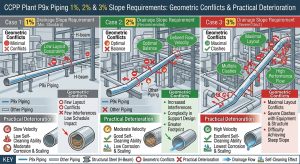
6.1 1%、2% 與 3% 洩水坡度需求下之幾何衝突與實務惡化 /6.1 Geometric Conflicts and Practical Deterioration under 1%, 2%, and 3% Drainage Slope Requirements
在這些擁擠的空間中,為了嚴格落實 ASME TDP-1 規範,主蒸汽管線必須具備至少 1%(即 1:100)的連續下傾洩水坡度3。然而,若設計或施工時為求更快速排除積水而將洩水坡度提高至 2%(每 100 呎下降 2 呎)或 3%5,對於依賴常規 1.5D 對銲彎頭的配管工程,將帶來更為嚴苛的幾何衝突與系統性應力風險: In these congested spaces, to strictly implement the ASME TDP-1 code, main steam pipelines must possess a continuous downward drainage slope of at least 1% (i.e., 1:100)3. However, if the drainage slope is increased to 2% (a 2-foot drop per 100 feet) or 3% during design or construction for faster water removal5, it will introduce far more severe geometric conflicts and systemic stress risks for piping projects relying on conventional 1.5D butt-welded elbows:
- 空間角度落差加劇:標準的1.5D 鍛造彎頭僅提供絕對的 45° 或 90° 轉向。若要維持 1% 的坡度,管線在三維空間中會產生約 0.57° 的角度偏移;若坡度提升至 2% 或 3%,角度偏移量將倍增至約 1.15° 與 1.72°。標準 1.5D 彎頭的固定幾何將完全無法自然吻合這些轉折路徑。Aggravation of Spatial Angle Discrepancies: Standard 1.5D forged elbows only offer absolute 45° or 90° turns. To maintain a 1% slope, a pipeline generates an angular offset of about 0.57° in three-dimensional space; if the slope increases to 2% or 3%, the offset doubles to approximately 1.15° and 1.72°. The fixed geometry of standard 1.5D elbows is entirely incapable of naturally conforming to these turning paths.
- 現場強制組對與斜切工法極端化:為了彌補 2% 或 3% 坡度帶來的較大角度落差,現場施工將被迫採取更極端的深度機械斜切(Trimmed Cuts),嚴重破壞彎頭曲率與幾何連續性2。若採用強制組對,所需的扳折外力將呈倍數上升,在系統內鎖入極大的初始殘留應力。 Extremization of Field Forced Fit-up and Trimming Methods: To compensate for the larger angle gaps caused by 2% or 3% slopes, field construction is forced to adopt more extreme deep mechanical trimming (Trimmed Cuts), severely destroying elbow curvature and geometric continuity2. If forced fit-up is utilized, the required bending forces multiply, locking massive initial residual stresses into the system.
- 流體動力學擾動與應力集中飆升:坡度越陡導致的斜切角度越大,高速蒸汽流經時遭遇的幾何突變越劇烈,進而產生更強大的分離泡與迪恩渦流,極大化流動加速腐蝕(FAC)的破壞力。由於特厚壁1.5D 彎頭理論柔性極差,無法吸收額外的三維位移應力,這些應力將集中於斜切銲接的細晶熱影響區(FGHAZ),極速催化微觀空孔串連,使「第四型潛變破裂」提前發生。Surge in Fluid Dynamic Disturbances and Stress Concentration: Steeper slopes lead to larger trimming angles, meaning the geometric abruptions encountered by high-speed steam are more violent. This generates stronger separation bubbles and Dean Vortices, maximizing the destructive power of Flow-Accelerated Corrosion (FAC). Because extremely thick-walled 1.5D elbows have very poor theoretical flexibility and cannot absorb additional 3D displacement stress, these stresses concentrate at the FGHAZ of the trimmed weld, rapidly catalyzing the interconnection of microscopic voids and accelerating the onset of “Type IV Creep Cracking.”
6.2 強制組對工法與全生命週期成本惡化 /6.2 Forced Fit-Up Methods and Deterioration of Life Cycle Costs
因此,若堅持採用標準彎頭,施工圖面上便會充斥大量無法完美銜接的非標準空間角。除了 1.5D 彎頭斜切工法外,部分現場施工單位為了節省機械裁切、重新開槽與繁瑣對心的時間成本,甚至採用了更為惡劣的「大小縫隙強行組對」(Forced Fit-Up with Uneven Root Gaps)工法。 Therefore, if the use of standard elbows is insisted upon, construction drawings will be flooded with non-standard spatial angles that cannot connect perfectly. Besides 1.5D elbow trimming methods, some field construction units, to save the time costs of mechanical cutting, re-beveling, and tedious alignment, have even resorted to an even more egregious method: “Forced Fit-Up with Uneven Root Gaps.”
此偏門工法係在對接標準的 1.5D 彎頭與直管時,刻意在銲道根部(Root Gap)製造一側間隙大、一側間隙小的楔形縫隙,利用外部機械外力(如大型鏈條吊車或千斤頂)強行扳折管線以達到洩水坡度,隨後在受力狀態下進行強制點銲與全滲透銲接。這嚴重違反 ASME 組對公差,並在系統內鎖入難以估算的巨大初始殘留應力。當管線升溫至 600°C 產生龐大熱應力時,輕則導致恆力吊架失效,重則直接在短時間內撕裂 P91 銲縫的細晶熱影響區,引發無預警破管。 This makeshift method involves intentionally creating a wedge-shaped root gap—large on one side and small on the other—when butting standard 1.5D elbows against straight pipes. External mechanical force (such as large chain hoists or jacks) is used to forcefully bend the pipeline to achieve the drainage slope, followed immediately by forced tack welding and full-penetration welding under stress. This severely violates ASME fit-up tolerances and locks an incalculable, massive initial residual stress into the system. When the pipeline heats up to 600°C and generates enormous thermal stress, this can, at minimum, cause constant effort hanger failures or, at worst, directly tear the FGHAZ of the P91 weld in a short time, causing unpredicted pipe rupture.
6.3 業主營運決策方針:P9x 管線選用 3D/5D 冷彎替代 1.5D 之長效效益 /6.3 Owner’s Operational Decision-Making Guidelines: Long-Term Benefits of Substituting 3D/5D Cold Bends for 1.5D in P9x Pipelines
鑑於上述強制組對與斜切工法帶來的極高營運風險,現代 CCPP 業主在制定營運決策與規範方針時,已逐步從「初期採購成本考量」轉向「全生命週期成本(LCC)與機組妥善率極大化」的宏觀視角。雖然市售常規 1.5D 鍛造彎頭材料單價較低,但若計入 P9x 特殊合金極其繁瑣的現場全滲透銲接、耗時耗能的銲後熱處理(PWHT),以及雙倍銲縫衍生的相控陣列超音波檢測(PAUT)費用與挖除修補風險,其整體建造成本已失去優勢。 In light of the extreme operational risks brought by the aforementioned forced fit-up and trimming methods, modern CCPP owners, when establishing operational decisions and code guidelines, have gradually shifted from “initial procurement cost considerations” to a macro perspective maximizing “Life Cycle Cost (LCC) and unit availability.” Although commercially available standard 1.5D forged elbows have lower unit material prices, when factoring in the extremely tedious field full-penetration welding of P9x special alloys, time- and energy-consuming Post-Weld Heat Treatment (PWHT), and the doubled Phased Array Ultrasonic Testing (PAUT) costs and excavation/repair risks resulting from double welds, their overall construction cost advantage is lost.
在營運階段,P9x 高能管線的「第四型潛變破裂(Type IV Cracking)」與流動加速腐蝕(FAC)是導致機組非計畫性停機(Forced Outage)的頭號殺手。一旦發生破管,業主面臨的不僅是天價的修繕費用,更是每日高達數百萬新台幣的發電中斷損失。因此,業主在決策方針上明確要求全面以 3D 或 5D 數控冷作彎管取代傳統 1.5D 彎頭。此一決策從物理與冶金層面徹底消除了高壓蒸汽幹管轉折處的高風險銲縫,大幅降低了營運期間的非破壞檢測負擔與破管停機風險,具備壓倒性的長期 LCC 經濟效益。 During the operational phase, “Type IV Creep Cracking” and Flow-Accelerated Corrosion (FAC) in P9x high-energy pipelines are the primary culprits behind forced outages. Once a pipe rupture occurs, the owner faces not only astronomical repair costs but also daily power generation interruption losses amounting to millions of NT Dollars. Therefore, owners have explicitly mandated in their decision guidelines the comprehensive substitution of 3D or 5D CNC cold bends for traditional 1.5D elbows. This decision fundamentally eliminates high-risk welds at the turning points of high-pressure steam mains from both physical and metallurgical standpoints. It dramatically reduces Non-Destructive Testing (NDT) burdens and pipe rupture risks during operation, yielding overwhelming long-term LCC economic benefits.
6.4 EPC 統包商設計單位之空間排列考量與管線路徑優化 /6.4 EPC Contractor Design Unit’s Spatial Arrangement Considerations and Pipeline Routing Optimization
為了貫徹業主的高可靠度需求,EPC(工程、採購、建造)統包商的設計單位在進行大潭與國光等電廠的管線佈置時,已全面轉向「能彎不銲」的先進設計理念。在廠房狹窄的鋼構間穿梭並維持 1% 至 3% 的連續洩水坡度時,管線勢必會產生諸多非標準角度。 To implement the owner’s high-reliability requirements, the design units of EPC (Engineering, Procurement, Construction) contractors, when laying out pipelines for plants like Datan and Kuokuang, have fully pivoted to the advanced design philosophy of “bend rather than weld.” Navigating through the narrow steel structures of the plant while maintaining a continuous drainage slope of 1% to 3% inevitably creates numerous non-standard angles in the pipelines.
相較於 1.5D 彎頭因固定幾何帶來的強制組對與空間佔用問題,設計單位透過導入 3D 或 5D 冷作彎管,可依據 3D 模型精準設定任意的彎曲半徑與彎曲角(如精準彎製至 88.2° 或 43.1°),實現管線在三維空間中的平順過渡。根據 ASME B31J 的應力計算回饋,3D/5D 大半徑彎管不僅不會受到特厚壁效應(h 值)而退化為剛性體,反而能提供極佳的柔性因子(k)與面內外 SIF 配置,從而完美吸收高能管線在複雜空間排列中所產生的龐大三維熱膨脹位移。這讓 EPC 設計師能在不增加額外銲接點的前提下,靈活地避開鋼構干涉並精準維持洩水坡度。 Compared to the forced fit-up and spatial occupation issues caused by the fixed geometry of 1.5D elbows, design units can import 3D or 5D cold bends to precisely configure arbitrary bend radii and bend angles (e.g., precisely bending to 88.2° or 43.1°) based on 3D models, achieving smooth pipeline transitions in 3D space. According to ASME B31J stress calculation feedback, 3D/5D large radius bends not only avoid degrading into rigid bodies due to the extreme thickness effect (h value) but actually provide excellent flexibility factors (k) and in-plane/out-of-plane SIF configurations. This perfectly absorbs the massive 3D thermal expansion displacements generated by high-energy pipelines within complex spatial arrangements. This allows EPC designers to flexibly bypass steel structure interferences and precisely maintain drainage slopes without adding additional weld points.
6.5 潁璋工程實務應用:P9x 冷作彎管 3D/5D 結合三合一工法之效益 /6.5 Ying Zhang Engineering’s Practical Application: Benefits of 3D/5D P9x Cold Bending Combined with the 3-in-1 Method
在台灣的電廠實務中,為了解決高能管線的痛點,潁璋工程興業有限公司(Ying Zhang Engineering)成功導入並推廣了針對 P91/P92 管材的「三合一工法」:「數控冷彎(CNC Cold Bending)+局部感應加熱管線彎後熱處理(IH-PBHT)+數位化模組管理」6。 In Taiwanese power plant practices, to address the pain points of high-energy pipelines, Ying Zhang Engineering Co., Ltd. has successfully introduced and promoted a “3-in-1 Method” tailored for P91/P92 pipe materials: “CNC Cold Bending + Localized Induction Heating Post-Bending Heat Treatment (IH-PBHT) + Digital Modular Management”6.
針對 P9x 特厚壁合金鋼材,潁璋工程捨棄了傳統的高週波熱彎,採用成熟的 3D/5D 數控冷作彎管技術8。冷作彎管在室溫下進行機械力彎曲,完全不經歷破壞性的高溫熱循環,從而最大程度地保留了 A335 P91/P92 母材原有的回火麻田散鐵組織、高溫強度及抗潛變性能9。彎製完成後,再輔以精確的次臨界感應加熱(IH-PBHT)消除加工硬化應力。 For P9x extremely thick-walled alloy steels, Ying Zhang Engineering has abandoned traditional high-frequency hot bending in favor of mature 3D/5D CNC cold bending technology8. Cold bending performs mechanical bending at room temperature, completely avoiding destructive high-temperature thermal cycles. Thus, it maximizes the retention of the original tempered martensite microstructure, high-temperature strength, and creep resistance of the A335 P91/P92 base metal9. Once bending is complete, precise subcritical Induction Heating (IH-PBHT) is supplemented to eliminate work-hardening stress.
在工程執行效益上,此「三合一工法」允許連續彎管作業,直接取代了傳統勞力密集的現場管段切割與拼接。這不僅大幅降低了對高階銲接技術人員及配管工的依賴,更完全免除了因現場銲接所衍生的 RT(射線檢驗)或 PAUT 檢測費用,以及後續挖除修補(剷修)的時間浪費8。透過工廠預製與數位化管理,管線能以極高的精準度送達現場進行吊裝,有效壓縮了現場施工期,完美契合了 EPC 統包商對專案進度的要求與業主對成本控管、長期穩定運轉的終極目標8。 In terms of engineering execution benefits, this “3-in-1 Method” permits continuous bending operations, directly replacing traditional labor-intensive field pipe cutting and splicing. This not only significantly reduces reliance on high-level welding technicians and pipefitters but also completely eliminates RT (Radiographic Testing) or PAUT inspection costs derived from field welding, as well as time wasted on subsequent excavation and repair8. Through factory prefabrication and digital management, pipelines can be delivered to the site for lifting with extreme precision, effectively compressing the field construction schedule. This perfectly aligns with EPC contractors’ project timeline requirements and the owners’ ultimate goals of cost control and long-term stable operation8.
七、 現代最佳替代方案總結:3D/5D 數控冷作彎管技術與幾何優勢 /7. Summary of the Best Modern Alternative: 3D/5D CNC Cold Bending Technology and Its Geometric Advantages
為了一勞永逸地解決 CCPP 電廠面臨的非標準三維空間角難題、嚴格維持洩水坡度連續性,現代高能管線工程以一體成型的 3D 或 5D 大半徑數控冷作彎管全面取代傳統的 1.5D 鍛造對銲彎頭,展現了無可取代的優勢: To permanently resolve the non-standard 3D spatial angle difficulties faced by CCPP plants and strictly maintain continuous drainage slopes, modern high-energy pipeline engineering is comprehensively replacing traditional 1.5D forged butt-welded elbows with integrally formed 3D or 5D large radius CNC cold bends, demonstrating irreplaceable advantages:
7.1 流體動力學與洩水坡度的完美契合 /Perfect Match with Fluid Dynamics and Drainage Slopes
數控冷彎技術能夠精確客製化任何非標準空間角度,無須在現場進行任何破壞幾何連續性的裁切或拼接組對。3D 或 5D 的大彎曲半徑(R≧3D)極大地降低了迪恩數(De),從根本上削弱了管內二次渦流的生成強度。同時,極度平順的曲率半徑完全消除了引發邊界層剝離的逆壓梯度,確保流線緊貼管壁,避免了分離泡與低速回流區的產生10。這不僅確保了高速蒸汽能將冷凝水穩定且持續地推向疏水點,完美實現洩水坡度的物理機能,更將流動加速腐蝕(FAC)的風險降至最低,大幅降低了系統壓降(Pressure Drop)。 CNC cold bending technology can precisely customize any non-standard spatial angle without needing any field cutting or splicing that destroys geometric continuity. The 3D or 5D large bend radius (R≧3D) dramatically lowers the Dean Number (De), fundamentally weakening the formation intensity of secondary vortices inside the pipe. Concurrently, the extremely smooth curvature radius completely eliminates the adverse pressure gradient that triggers boundary layer separation, ensuring streamlines closely hug the pipe wall and avoiding the creation of separation bubbles and low-speed recirculation zones10. This not only guarantees that high-speed steam pushes condensate steadily and continuously toward the drain points—perfectly realizing the physical function of the drainage slope—but also minimizes the risk of Flow-Accelerated Corrosion (FAC) and significantly reduces system Pressure Drop.
7.2 應力分佈優化與消弭第四型潛變破裂 /Stress Distribution Optimization and Elimination of Type IV Creep Cracking
其最為核心且具決定性的優勢,在於冶金領域的徹底解套。一體成型的冷彎工法直接消除了管線轉折處(系統中承受最大彎矩與應力集中的作用點)的銲縫。沒有銲接熱循環,就沒有微觀組織劣化的細晶熱影響區(FGHAZ),從物理機制上完全根絕了此關鍵節點發生第四型潛變破裂(Type IV Cracking)的任何可能性。 Its most core and decisive advantage lies in completely untying the knot in the metallurgical realm. The integrally formed cold bending method directly eliminates the weld at the pipeline turning point (the action point bearing the maximum bending moment and stress concentration in the system). With no welding thermal cycles, there is no microstructurally deteriorated Fine-Grained Heat-Affected Zone (FGHAZ). From a physical mechanism standpoint, this completely eradicates any possibility of Type IV Creep Cracking occurring at this critical node.
下表綜合比較了傳統工法與現代冷彎工法在各項關鍵工程指標上的差異:The following table comprehensively compares the differences between traditional methods and modern cold bending methods across key engineering indicators:
| 評估維度/ Evaluation Dimension | 1.5D 鍛造對銲彎頭 (斜切/強制組對)/ 1.5D Forged Butt-Welded Elbow (Trimmed/Forced Fit-Up) | 3D / 5D 數控大半徑冷作彎管工法 (含三合一工法)/ 3D / 5D CNC Large Radius Cold Bending Method (including 3-in-1 Method) |
| 洩水坡度適應性/ Drainage Slope Adaptability | 極差。需破壞幾何或產生巨大殘留應力以勉強達標/ Extremely poor. Requires destroying geometry or creating massive residual stresses to barely meet standards. | 極佳。可利用數控技術精確無縫客製化任意非標準空間角/ Excellent. CNC technology can seamlessly and precisely customize any non-standard spatial angle. |
| ASME B31J 應力表現/ ASME B31J Stress Performance | 柔性極差,特厚壁下 k 強制收斂於剛性極限值 1.0/ Extremely poor flexibility; under thick walls, k mandatorily converges to the rigid threshold of 1.0. | 柔性配置優良,有效吸收密佈管線之三維熱膨脹位移/ Excellent flexibility configuration; effectively absorbs 3D thermal expansion displacement of dense pipelines. |
| 流體力學與 FAC 風險/ Fluid Dynamics & FAC Risk | 產生強烈分離泡、滯水區及迪恩渦流,FAC 與水錘風險極高/ Generates intense separation bubbles, dead-water zones, and Dean Vortices; FAC and water hammer risks are extremely high. | 曲率平順連續,邊界層穩定,大幅降低壓降、沖刷與積液風險/ Smooth and continuous curvature, stable boundary layer; significantly reduces pressure drop, erosion, and pooling risks. |
| 冶金完整性與潛變風險/ Metallurgical Integrity & Creep Risk | 高應力轉折區存在銲縫,FGHAZ 面臨極高 Type IV 破裂風險/ Welds exist in high-stress turning zones; FGHAZ faces extremely high Type IV cracking risk. | 轉折區零銲縫,冷彎保留 P9x 原有強化機制,無 Type IV 破裂風險/ Zero welds in turning zones; cold bending retains P9x original strengthening mechanisms; no Type IV cracking risk. |
| 全生命週期成本 (LCC)/ Life Cycle Cost (LCC) | 前期材料成本略低,但現場銲接、NDT、重工及破管停機風險極高/ Initial material cost slightly lower, but extremely high risks in field welding, NDT, rework, and pipe rupture outages. | 現場免銲接、免 RT/PAUT、大幅縮短工期,LCC 經濟效益壓倒性勝出8/ Field weld-free, RT/PAUT-free, dramatically shortened schedule; overwhelming LCC economic benefit8. |
八、 結論 /8. Conclusion
針對 2026 年版 ASME B31J 應力規範以及 ASME TDP-1 汽輪機防護標準的嚴格檢視,本研究深入剖析了 P9x 高壓蒸汽管線在維持 1:100 及以上洩水坡度時所面臨的幾何與力學困境。在台灣大潭與國光等 CCPP 電廠頻繁啟停與急速升降載的嚴苛運轉環境下,高能管線長期承受極端的高溫潛變與交變熱疲勞交互作用。傳統因應非標準空間角所採用的 1.5D 彎頭斜切或大小縫強制組對工法,在 B31J 應力深度解析下被證實幾乎不具備任何柔性吸能作用,且引發嚴重的流體邊界層分離與迪恩渦流,徹底摧毀洩水坡度的排液功能。Under the strict scrutiny of the 2026 ASME B31J stress code and the ASME TDP-1 steam turbine protection standard, this study deeply analyzed the geometric and mechanical dilemmas faced by P9x high-pressure steam pipelines when maintaining drainage slopes of 1:100 and above. In the severe operating environments of Taiwan’s Datan and Kuokuang CCPP plants, characterized by frequent start-ups and rapid load cycling, high-energy pipelines endure the interactive effects of extreme high-temperature creep and alternating thermal fatigue over the long term. Traditional methods adopted to handle non-standard spatial angles, such as 1.5D elbow trimming or forced fit-up with uneven root gaps, are proven through in-depth B31J stress analysis to possess almost no flexible energy-absorbing capability. Furthermore, they trigger severe fluid boundary layer separation and Dean Vortices, completely destroying the drainage function of the slopes.
更為致命的是,採用 1.5D 彎頭斜切工法,等同於在系統應力集中處人為引入了 P91/P92 鋼材最脆弱的細晶熱影響區(FGHAZ),埋下第四型潛變破裂(Type IV Cracking)的致命隱患。綜合業主決策方針、EPC 空間設計優化,以及潁璋工程導入「冷作彎管+感應加熱彎後熱處理+數位化管理」三合一工法的實務效益評估,本研究強烈建議現代高能管線設計應徹底揚棄傳統短半徑管件的現場拼接思維,全面導入 3D 或 5D 大半徑數控冷作彎管工法。這不僅能確保廠房佈局與洩水坡度的完美契合,更是保障電廠長期運轉安全、消弭災難性破裂風險並極大化全生命週期效益的唯一最佳工程路徑。More fatally, employing the 1.5D elbow trimming method equates to artificially introducing the most fragile Fine-Grained Heat-Affected Zone (FGHAZ) of P91/P92 steel into the system’s stress concentration point, planting a lethal hidden danger of Type IV Creep Cracking. Integrating the owner’s decision-making guidelines, EPC spatial design optimization, and the practical benefit evaluation of Ying Zhang Engineering’s 3-in-1 Method (“Cold Bending + Localized Induction Heating PBHT + Digital Management”), this study strongly recommends that modern high-energy pipeline design thoroughly abandon the field-splicing mindset of traditional short-radius fittings and comprehensively adopt the 3D or 5D large radius CNC cold bending method. This not only ensures a perfect match between the plant layout and drainage slopes but is also the singular best engineering path to safeguarding the long-term operational safety of power plants, eliminating catastrophic rupture risks, and maximizing lifecycle benefits.
參考文獻/ References
- https://yz-pipe-bending.com.tw/%E8%A4%87%E5%BE%AA%E7%92%B0%E9%9B%BB%E5%BB%A0%E9%AB%98%E8%83%BD%E7%AE%A1%E7%B7%9A%E9%9D%9E%E6%A8%99%E6%BA%96%E7%A9%BA%E9%96%93%E8%A7%92%E8%88%87%E6%B4%A9%E6%B0%B4%E5%9D%A1%E5%BA%A6%E8%A8%AD%E8%A8%88/
- https://yz-pipe-bending.com.tw/%E5%9F%BA%E6%96%BC-2026-asme-b31j-%E8%A6%8F%E7%AF%84%EF%BC%9Ap91-%E9%AB%98%E5%A3%93%E8%92%B8%E6%B1%BD%E7%AE%A1%E7%B7%9A%E6%B4%A9%E6%B0%B4%E5%9D%A1%E5%BA%A6%E8%A8%AD%E8%A8%88%E6%8E%A1%E5%8F%96%E5%B0%8D/
- https://yz-pipe-bending.com.tw/%E8%A4%87%E5%BE%AA%E7%92%B0%E9%9B%BB%E5%BB%A0%E9%AB%98%E5%A3%93%E8%92%B8%E6%B1%BD%E7%AE%A1%E7%B7%9A%E6%B4%A9%E6%B0%B4%E5%9D%A1%E5%BA%A6%E8%A8%AD%E8%A8%88%E8%88%87%E7%AE%A1%E4%BB%B6%E5%B7%A5%E6%B3%95/
- Piping Specific System Considerations, https://www.littlepeng.com/single-post/2018/02/09/piping-specific-system-considerations
- Process Piping Fundamentals, Codes and Standards, https://www.cedengineering.com/userfiles/Process%20Piping%20Fundamentals,%20Codes%20and%20Standards%20%20-%20Module%201.pdf
- 顛覆傳統管線工程:針對CCPP建廠業主與EPC統包商去銲接化與模組, https://yz-pipe-bending.com.tw/%E9%A1%9B%E8%A6%86%E5%82%B3%E7%B5%B1%E7%AE%A1%E7%B7%9A%E5%B7%A5%E7%A8%8B%EF%BC%9A%E9%87%9D%E5%B0%8Dccpp%E5%BB%BA%E5%BB%A0%E6%A5%AD%E4%B8%BB%E8%88%87epc%E7%B5%B1%E5%8C%85%E5%95%86%E5%8E%BB%E9%8A%B2/
- 先進CCPP 高能管線彎徑標準化設計——基於ASME B31J 應力解析與, https://yz-pipe-bending.com.tw/%E7%AA%81%E7%A0%B4%E6%A5%B5%E7%AB%AF%E5%B7%A5%E6%B3%81%EF%BC%9A%E5%85%88%E9%80%B2-ccpp-%E9%AB%98%E8%83%BD%E7%AE%A1%E7%B7%9A%E5%BD%8E%E5%BE%91%E6%A8%99%E6%BA%96%E5%8C%96%E8%A8%AD%E8%A8%88/
- 冷作彎管之配管工程化 – 潁璋工程興業有限公司, https://yz-pipe-bending.com.tw/test/
- 針對P91 &P92合金鋼材,熱彎曲與冷彎曲加工有何差異不同?, https://yz-pipe-bending.com.tw/%E9%87%9D%E5%B0%8Da335-p91-p92%E5%90%88%E9%87%91%E9%8B%BC%E6%9D%90%E5%85%B6%E7%86%B1%E5%BD%8E%E6%9B%B2%E8%88%87%E5%86%B7%E5%BD%8E%E6%9B%B2%E6%9C%89%E4%BD%95%E5%B7%AE%E7%95%B0%E4%B8%8D%E5%90%8C/
- Nickel Alloy 200/201 Long Radius Bend in India, http://www.pipefittingsmanufacturers.com/special-alloy-buttweld-long-radius-bends-manufacturers-exporter.html